Table of Contents
Advertisement
Quick Links
Advertisement
Table of Contents

Related Manuals for Omni3D Omni500 LITE

Summary of Contents for Omni3D Omni500 LITE
- Page 1 Omni500 LITE User’s Manual Version 1.3 01.01.2022...
-
Page 2: Table Of Contents
RINTER 1.2 M 500 LITE OMPONENTS OF 1.3 T ECHNICAL PECIFICATIONS 2 FILAMENTS SUPPORTED BY OMNI3D 2.1 G LUES COMPATIBLE WITH SPECIFIC FILAMENTS 2.2 S UPPORT FILAMENTS COMPATIBLE WITH PARTICULAR BASE MATERIALS 2.3 P RINTHEAD MODULES TYPES 3 SAFETY AND COMPLIANCE 3.1 P... - Page 3 4.3 R EINSTALLING THE RINTER 5 PREPARATION FOR THE FIRST START-UP 5.1 L OADING THE ATERIALS 5.2 C ALIBRATING THE PRINTER NSTALLATION OF A ETWORK FOR NLINE PERATION 5.2.1 N ETWORK ONFIGURATION SING AN THERNET ABLE 5.2.2 W ETWORK ONFIGURATION 5.2.3 A CCESS OINT...
-
Page 4: Legal Information
Omni3D 3D printers work in incremental technology (gradual layering of molten filament). The precision and speed of printing offered by the Omni500 LITE make it a perfect device for making prototype models and small-lot production. Despite the Omni500 LITE's ability to handle multiple... -
Page 5: Introduction
1 Introduction The document below provides safety and operating information for the Omni500 LITE printer. Before starting work, carefully read all the information and follow the instructions in the following document. Recommendations and notes allow you to obtain high-quality prints and minimize potential risks. -
Page 6: Intended Use Of The Printer
1.1 Intended use of the Printer The Omni500 LITE 3D printer is used for layering of liquid filament according to a prepared G-code file in order to transform a virtual model saved in the * .stl format into a real spatial object. -
Page 7: Main Components Of Omni500 Lite
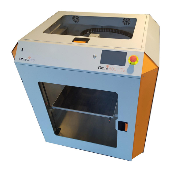
1.2 Main Components of Omni500 LITE Figure 1 Omni500 LITE Printer 1. SD card reader 5. Glass work platform of the printer 2. Front and top doors 6. Touch LCD display 3. Top cover of the extruder assembly 7. Emergency stop switch... - Page 8 Figure 2 Omni500 LITE Printer 1. Camera 2. Ventilation grille 3. The main switch of the printer 4. Power socket 5. Channels for transporting the printer...
-
Page 9: Technical Specifications
1.3 Technical Specifications Table 1 Omni500 LITE printer specifications Printing technology FFF (fusedfilamentfabrication) X Y Z workspace 460 x 460 x 600mm Chamber Closed 50μm Minimum layer height Number of print heads Nozzle diameter Work platform surface Glass Max. head temperature 360°C... -
Page 10: Filaments Supported By Omni3D
The printer is able to work on many other materials! The materials listed here are tested by us and we have created ready profiles for them. The range of materials is regularly extended as OMNI3D works on creating print profiles for new materials. To access the current list of supported materials please visit the website at: https://www.omni3d.com/3d-printing/filaments/... -
Page 11: Glues Compatible With Specific Filaments
2.1 Glues compatible with specific filaments Table 3 Glues compatible with specific filaments Glue type Compatible filament ABS-42 HIPS-20 ASA-39 PC-ABS-47 PET-G-32 DIMAFIX TPU-93A PLA-36 THERMEC™ ZED ODS-20 PVA-20 CF PA-12 PA-6/66 HD XSTRAND™ GF30-PA6 2.2 Support filaments compatible with particular base materials Table 4 Base filament and support filament compatibility COMPATIBLE SUPPORT MATERIAL BASE MATERIAL... -
Page 12: Printhead Modules Types
2.3 Printhead modules types AVAILABLE NOZZLE CATALOGUE MAX. NOZZLE COLOUR SPECIFICATION NOZZLE TYPE NUMBERS TEMP. DIAMETERS FL500KPBR040 0,4 mm Teflon lining FL500KPBR060 Brass nozzle 0,6 mm 240°C Aluminium heating FL500KPBR080 0,8 mm block 0,4 mm FL500KSBR040 Steel heatbreak 0,6 mm Brass nozzle FL500KSBR060 360°C... -
Page 13: Safety And Compliance
3 Safety and Compliance Pictograms on the machine Caution! Hot surface Hand crushing hazard You must wear protective gloves You must wear safety googles High voltage Figure 3 Pictograms on the machine... -
Page 14: General Requirements
General requirements In order to ensure the safety of persons present in the vicinity of the machine, instruments and safety elements on the machine, the user shall strictly follow the general safety rules: The machine may be operated only if its technical condition is good. When the machine is in operation, the guards must be in place and remain closed. -
Page 15: Hazard Identification
Hazard identification Mechanical hazards 3.3.1 Movement of extruder modules along the X- and Y-axes and mechanically connected elements 3.3.1.1 Figure 4 Direction of movement of extruder modules... - Page 16 Movement of the platform along the Z-axis and the related elements 3.3.1.2 Figure 5 Direction of movement of the platform Rotational movement of fans 3.3.1.3 Figure 6 Fan...
-
Page 17: Thermal Hazards
Damage to the glass surface of the platform 3.3.1.4 For process-related reasons, the working surface of the machine table upon which items are printed is made of glass. There is a risk of rapid uncontrolled breaking of the glass plate due to thermal and mechanical factors. -
Page 18: Electric Shock Hazard
Figure 7 Thermal hazards (nozzle and platform) Electric shock hazard 3.3.3 Electric shock hazard due to direct and indirect contact with live elements operated at a dangerous 3.3.3.1 voltage Electric shock hazard due to indirect or direct contact with components operated at a dangerous 3.3.3.2 voltage due to leakage of the liquid cooling extruder modules. -
Page 19: Protective Measures
Protective measures Guards 3.4.1 Fixed guards 3.4.1.1 The working zone of the machine is secured by fixed guards, which prevent accessing hazardous areas during machine operation. The access to fans is secured with fixed local guards to prevent any access to the hazardous area during machine operation. - Page 20 Figure 9 Nozzle guards Interlocking guards – front and top hatches 3.4.1.2 Access to the working chamber is secured with interlocking guards, i.e. front and top hatches. Opening any interlocking guard during operation will stop all drives. Opening any interlocking guard during operation may result in irreversible damage to the printed item.
-
Page 21: Emergency Stop Device
Figure 10 Interlocking guards Movable guard of the filament compartment 3.4.1.3 The filament compartment is covered with a movable guard, i.e. a hatch to protect the filament from contamination. There is no access to the working chamber through the filament compart-ment. It is recommended to keep the hatch to the filament compartment closed at all times. -
Page 22: Electrical Equipment
Caution! Pressing the emergency stop button does not cut supply to the control cabinet. Prior to any interference in electronics, it is necessary to disconnect supply voltage by disconnecting the two power cables. Caution! Pressing the emergency stop button does not prevent access to hot machine components. -
Page 23: Pictograms
Pictograms 3.4.4 The machine is provided with information and warning pictograms relating to hazards and the necessity to apply personal protective equipment. For the description of pictograms placed on the machine, see 2.1. Disconnecting the power source For disconnection of the machine from the power source, there is a plug & socket connection. Disconnection of the power supply requires disconnection of the two power cables. -
Page 24: Emergency Measures
Emergency measures In case of an immediate need, an error or another failure, it is necessary to: 1. Stop the machine by pressing the emergency stop button; 2. Secure the danger zone so that nobody can enter or encroach it unwittingly; 3. -
Page 25: Required Operator Qualifications
Required operator qualifications Independent operation of the machine requires the operator to: 1. Be of full legal age. Underage persons during training or instruction cannot perform any job at the machine without supervision of an adult authorised to operate the machine by the employer; 2. -
Page 26: Safety Requirements During Maintenance And Repairs
Safety requirements during maintenance and repairs 3.10 Prior to any work, disconnect the supply by disconnecting the two power cables. Keep the power cables away so that no authorised connection to the machine can be established. Maintenance and repairs can be performed only by personnel holding the appropriate qualifications. -
Page 27: Residual Risk
Residual risk 3.11 Application of technical protective measures does not protect from access to hot surfaces. Activation of the emergency stop function or supply disconnection by disconnection of the power cables does not reduce the risk of burns due to direct contact with hot surfaces. Hazardous areas are marked with pictograms and indicated in 2.3.2 in the operating manual (“Thermal hazards”). -
Page 28: Unpacking
4 Unpacking After delivering the printer, unpack it carefully, and then proceed with the installation as described in this chapter. -
Page 29: Dismantling The Transport Box
Noticed irregularities should be reported immediately (preferably when the printer is delivered) to the forwarding agent, always before unpacking the transport box. The Omni500 LITE printer is delivered in a special reusable transport box for safe transport. Follow the instructions below to properly disassemble the Omni500 LITE printer. - Page 30 1. 7. Remove the printer from the pallet using an appropriate cart using the transport channels shown in Figure 5. Figure 14 Removing the transport box Figure 15 Printer before removing from the pallet...
-
Page 31: Printer Installation
For safety reasons, both for the printer and the people performing the installation, when removing the printer from the pallet, be careful not to let the printer fall to the ground. 4.2 Printer Installation After removing the printer from the pallet, it should be transported to the destination that should meet the appropriate conditions: 1. - Page 32 4.3 Reinstalling the Printer It is recommended that the printer installation is carried out each time by the Manufacturer or the Manufacturer's Authorized Service Center, which will always be confirmed by the Installation Service Report, under pain of losing the warranty rights. It is allowed to change the place of printer installation carried out outside the Authorized Service Center.
- Page 33 5 Preparation for the first start-up After completing all the steps in Chapter 3, prepare the printer for first use. The following chapters explain how to load filament, calibrate, configure the online network and prepare the software for creating .gcode files.
- Page 34 5.1 Loading the Materials Before starting to print, load the appropriate material (filament) into the appropriate print heads. For the first start of the printer, we recommend using ABS-42 for the left head and HIPS-20 for the right head. When using the indicated filaments, there is the lowest risk of non-standard deviations in the printout, which results in a better reflection of the print quality during the test.
- Page 35 5.2 Calibrating the printer After loading the filament, you should start calibrating the device. The entire calibration process consists of several steps: leveling the table, setting the offset between the heights of both heads and setting the X and Y axis offsets. We start by launching the platform leveling process.
- Page 36 Figure 19 The requirement to correct the X axis offset (arrows precisely point at each other at position 0.3) If we obtain the situation as in the picture above, change the X axis offset in the appropriate menu (Figure 10) by clicking the indicated value until the parameter increases by 0.3. Figure 20 X and Y axis offset adjustment menu After making corrections to the X and Y offsets, perform the same printout again to make sure that the entered values improved the print quality.
- Page 37 Figure 21 List of procedures Optional functionality Platform Mesh Compensation - for use only when printing with one head raised (single head), creates a map of platform irregularities and compensates during printing by constantly moving the Z axis. This process allows you to get a better first layer in non-raft printing. The calibration process should be repeated in specific situations: •...
- Page 38 Connected and will present the assigned IP address below. After obtaining the IP address, enter it into a web browser on a computer connected to the same network. After correct connection, the Omni500 LITE remote control panel should appear. 5.2.2 Wi-Fi Network Configuration When you want to use a wireless network, select the Wi-Fi option in the Settings>...
- Page 39 Access Point 5.2.3 Configuration The printer has the ability to create a completely new network to which it will be possible to connect remotely within a limited range from the printer. To start the Access Point mode, select the Access Point button in the Settings>...
- Page 40 Simplyfy3D Installation At https://www.simplify3d.com/, log in via the Account tab (Figure 12). After logging in, go to the Download Software tab and select the software version that suits your system and then download it (Figure 13). Figure 22 Logging in to Simplify Figure 23 Downloading Simplify Install in accordance with the instructions displayed during the installation.
- Page 41 Run Simplify3D and log in with the same data as on the website (Figure 14). Figure 24 Login To add the Omni500 LITE configuration, select the Other option from the list of devices, go on and then change the parameters to the appropriate data.
- Page 42 Skip the next step with the Next button and finish the configuration with the Finish button. In the next step, prepare the profile files prepared by Omni3D (* .fff extension). These profiles were delivered on an SD card inside the printer's SD port and by e-mail from the manufacturer's representative.
- Page 43 6 Operation After assembly, you can start printing, and this chapter describes: • Operation of the LCD screen • Preparation of files for printing • Start of printouts and their removal • Removal of support material • Use of various printer configurations.
- Page 44 6.1 Touch Screen The control of the Omni500 LITE printer is performed using a touch LCD screen. A welcome logo will be displayed during the printer startup, then the screen will display the main menu. Interface The main menu allows you to navigate between the different levels of the interface. The entire...
- Page 45 Mechanics This tab is directly responsible for all mechanical changes inside the printer, e.g. the position of the extruders, defining the active head, changing the filament or starting processes such as e.g. auto- leveling the table or setting the head height. Figure 30 Mechanics Menu Settings It allows you to set a code to unlock the LCD display and remote control, define an internet...
- Page 46 Simplify3D 6.2 Preparing .gcode in To prepare .gcode files, use the Simplify software recommended by Omni3D. The software installation process has been described previously (4.3). Interface After starting Simplify3d, a window for working with 3D models will appear. The main functionalities are visible on the start screen (Figure 22 and Figure 23).
- Page 47 FFF settings contains the following setting parameters: • Select profiles: Here you can find all pre-loaded-ready settings (print profiles), defined by Omni3D for recommended materials (if after extending the list you do not have profiles defined by Omni3D, go back to 4.3 and import FFF profiles).
- Page 48 • Auto-Configure for Material: Some materials have similar print parameters which allowed to define several materials in one profile. In this case, both materials will be included in the profile name. • Auto-Confgure for Quality: It is used to change the printing speed, usually the faster the worse the quality of the printed model.
- Page 49 If you are satisfied with the print preview, you can start sending data via USB or saving the file. In the case of Omni500 LITE we are interested in recording on a medium, so we should choose the second option and indicate the destination of the saved file.
- Page 50 6.3 Start printing The Omni500 LITE printer can be managed manually (directly at the printer) or remotely using Wi-Fi or Ethernet. Before each printout, make sure that: • The platform is leveled • The glass surface of the platform is firm and does not move •...
- Page 51 6.3.1 Manual Before printing, prepare a .gcode file, instructions on creating files with the .gcode extension are provided in 5.2. Before preparing the file and implementing it into the printer, we recommend setting the appropriate temperatures in the printer, according to the recommendations for the appropriate material.
- Page 52 Figure 39 Selecting a file for printing Figure 40 Sample file list...
- Page 53 6.3.2 Remote Before starting to print, make sure that the printer's working area is clean and there are no objects on it. Otherwise, the printer heads may be damaged. To manage printouts via the Internet, a network connection is required. If you have not yet adapted the printer for remote control, go back to chapter 0.
- Page 54 6.4 Removing a Printout Warning! After finishing the printing, do not open the working chamber door until the temperature of the build plate drops below 50 ° C. Earlier opening of the working chamber may result in deformation of the printout. 1.
- Page 55 6.5 Postprocessing The Omni500 LITE printer has two heads, which allows simultaneous printing with 2 different filaments. In the case of complex structures, it is particularly useful because you can use a support filament, which provides adequate support for advanced geometries during printing, and can be easily removed after printing.
- Page 56 The rinsing process can be accelerated by increasing the water temperature to a maximum of 70 ° C. It should be remembered that some materials deform at lower temperatures, so before using warm water, check the softening point in the filament's technical data sheet and adjust the maximum temperature to the filament used.
- Page 57 Preheat list. This solution allows you to speed up the printing start process. The Omni3D company tries to expand the range of available materials, so the list may expand with subsequent software updates. After receiving new print profiles, upload them to the preheat list using a remote web panel.
- Page 58 7 Printer Maintenance Regular maintenance is required to keep your printer ready to print and to produce high-quality prints. The following chapter will explain the most important aspects of proper device maintenance.
- Page 59 7.1 Updating the Printer Software The printer software is constantly being developed. Each subsequent firmware version increases the parameters and makes the printer more reliable. Therefore, for the best optimization it is recommended to update the firmware. Information about an available update is delivered by e-mail to the indicated addresses, the message contains both the notification and the files required to update the printer software.
- Page 60 7.2 Filament Storage In order for the filament to retain the appropriate properties, remember to properly store the filament. It is generally accepted that filaments need to be stored in a dry and cool room. Some filaments are extremely adversely affected by air humidity, so it is recommended to heat them up. For a pre-packed filament, a cool room is sufficient, while after opening, air humidity should be taken into account in order to avoid problems related to the poor condition of the filament, it is recommended to use special filament dryers.
- Page 61 7.3 Maintenance Schedule 1. Maintenance performer by user: Table 7 User Maintenance Schedule worktime* printtime* Maintenance and service activities Thorough cleaning of the glass build plate Cleaning of extruder gears, Cleaning the inside of the printer Lubrication of the X and Y axis carriages CARBON / HEPA filters replacement Checking the working chamber fans, 1000...
- Page 62 7.3.1 User Maintenance After every 100 hours: In order to thoroughly clean the platform, remove it from the working chamber. In order to remove it, turn the lever as shown in the figure below and then manually remove it. Figure 47 Removing the glass work platform The work platform is easiest to clean under running water or using a sponge with water.
- Page 63 After every 200 hours: Cleaning the extruder gears. Unscrew the screw indicated in the figure below and then use compressed air to clean the inside of the extruder. In the case of larger contamination, the filament sections can be removed with tweezers. Figure 48 Inside of the left extruder (racks), set screw - right extruder Cleaning the inside of the printer.
- Page 64 The most important cleaning components are listed in the maintenance chart for the Omni500 LITE. However, in order to achieve the best possible quality of prints, the printer should be in perfect condition. When cleaning the printer, pay particular attention to: •...
- Page 65 7.5 Replacing CARBON/HEPA Filters You can order a filter for cleaning the air exhausted from the working chamber for the purchased printer. Below is a brief installation instruction for said filter. 1) Unscrew the bolts indicated (3mm IMBUS wrench) in the figure below. Figure 49 Location of CARBON / HEPA filter holders...
- Page 66 2) Fix the angles using the removed screws as shown in the drawing below. Figure 50 Properly installed CARBON / HEPA filter holders 3) Then proceed to install the filter using the previously attached holders. When positioning the filter, remember to adjust the height so that the top surface is flush with the top of the printer. Figure 51 CARBON / HEPA filter assembly process...
- Page 67 Lubrication of the X and Y axis carriages The carts are lubricated directly inside the printer's working chamber. Before lubricating, prepare the grease gun with a grease recommended by Omni3D. Figure 52 GN-80M lubricator and tip Then fit the lubricator with a lubricating tip, put it on the grease fitting and start filling the cart with grease.
- Page 68 Figure 54 Lubricating the Y axis carriages Lubrication of the Z axis carriages Figure 55 Lubricating the Z carriage Repeat the operation on each of the 3 Z axis lubrication carriages (carriages locations are shown below) Figure 56 Location of all Z axis carriages...
- Page 69 7.7 Checking Printer Fans The Omni500 LITE printer includes the following fans: • 2x electronics fan • PCB fan • Extruder's 2x heatsink fan • 2x chambers blowing fan • 2x printout cooling fan Inspection of the fans consists of a visual inspection of each fan and the placement of hands on it, and assessing whether the fans are operating properly.
- Page 70 PCB blower Check the single fan next to the electronics board by putting your hand on it and checking the force of air draft. If uneven operation is visible or the blower does not rotate at all, report the need for replacement to an Authorized Service Center.
- Page 71 Figure 59 Right extruder heatsink fan Figure 60 Left extruder heatsink fan Ventilation fans Two pieces mounted on the back of the printer. The check consists of a visual inspection of the operation. If uneven operation is visible or the fans do not rotate at all, report the need to replace them to an Authorized Service Center.
- Page 72 Figure 61 Fans blowing out the chambers Printout cooling blowers The blowers are located behind the heads when viewed from the front of the printer, start the blower using the touch screen and check if it works properly. If uneven operation is visible or the blowers do not rotate at all, report the need to replace them to an Authorized Service Center.
- Page 73 7.8 Printer head module replacement There are identification symbols on the cable connector which identify model with which the head module is compatible: 0.4, 0.,6, 0.8 is the nozzle diameter in [mm]. F – Factory 2.0, N – Factory 2.0 NET and L – 500 Lite (head modules are not interchangeable with each printers) In order to replace the head module, unplug the connector, loosen the thumb screw and pull the module down.
- Page 74 Figure 64 head module replacement...
Need help?
Do you have a question about the Omni500 LITE and is the answer not in the manual?
Questions and answers