Table of Contents
Advertisement
Quick Links
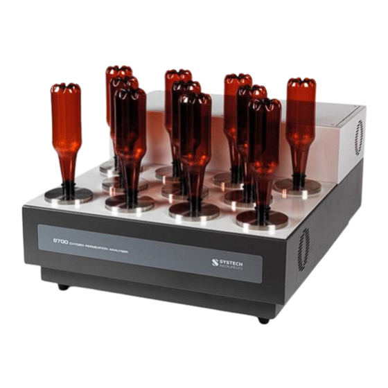
MODEL 8700
OXYGEN PERMEATION
ANALYSER
FOR BOTTLES
OPERATOR'S MANUAL
Version 2.9
26
th
July 2021
Industrial Physics Ltd
Industrial Physics Product Integrity Ltd
68 Barnum Road
17 Thame Park Business Centre
Devens
Wenman Road
Massachusetts
Thame
01434-3508
Oxfordshire
OX9 3XA
E: PiSales@industrialphysics.com
E: PiSalesUK@industrialphysics.com
www.systechillinois.com
Advertisement
Table of Contents

Related Manuals for Industrial physics SysTech Illinois 8700

Summary of Contents for Industrial physics SysTech Illinois 8700
- Page 1 MODEL 8700 OXYGEN PERMEATION ANALYSER FOR BOTTLES OPERATOR’S MANUAL Version 2.9 July 2021 Industrial Physics Ltd Industrial Physics Product Integrity Ltd 68 Barnum Road 17 Thame Park Business Centre Devens Wenman Road Massachusetts Thame 01434-3508 Oxfordshire OX9 3XA E: PiSales@industrialphysics.com E: PiSalesUK@industrialphysics.com...
-
Page 2: Table Of Contents
Model 8700 Operator’s Manual v2.9 Table of Contents INTRODUCTION ......................... 1 1.1 BRAND............................1 PRINCIPLE OF OPERATION ..................... 2 INSTALLATION ........................3 3.1 VOLTAGE INPUT/FUSE CARTRIDGE ..................3 3.2 CONNECTING GAS LINES ...................... 3 3.3 INSTALLATION OF COMM PORTS CONTROLLER ..............4 SOFTWARE ........................ - Page 3 Model 8700 Operator’s Manual v2.9 Revision History Issue Issue Date Changes 08-08-2008 Current Release Version Bryan Cummings 06-11-2009 Format changes, updated to mark II 8700. Nick Stuart 10-09-2009 Updated with additional info and new branding. Nick Stuart 02-04-2013 Added to troubleshooting section Bryan Cummings 06-04-2017 Editorial, new PC software V2.3b8 and AR0266...
-
Page 4: Introduction
We are proud of our active program of research and development. If you encounter any difficulties, we would like to hear about them. 1.1 BRAND Systech Illinois is a division of Industrial Physics. Throughout this manual, Industrial Physics, Industrial Physics Product Integrity, Systech, Systech Illionois and Systech Instruments are used interchangeably. -
Page 5: Principle Of Operation
Model 8700 Operator’s Manual v2.9 PRINCIPLE OF OPERATION The 8700 incorporates our proprietary, coulometric, oxygen sensor to detect oxygen transmission rates through all types of bottles or packages. Bottles / packages are fitted onto their respective adaptor using a fast-setting epoxy adhesive (3-5 minutes setting time). An oxygen-free (99.999% zero grade N ) carrier gas flows through the bottle. -
Page 6: Installation
Model 8700 Operator’s Manual v2.9 INSTALLATION 3.1 VOLTAGE INPUT/FUSE CARTRIDGE The power entry module is on the back of the instrument it not only allows attachment of the power cord, but also contains the fuses. Supply voltage is 90-260 VAC, 50-60Hz. Note that the cartridge contains two fuses. -
Page 7: Installation Of Comm Ports Controller
Model 8700 Operator’s Manual v2.9 3.3 INSTALLATION OF COMM PORTS CONTROLLER Note: This is required for some computer systems which either do not have an RS232 comms port fitted or where the existing comms port is already in use. Install the COM port controller board (or USB – RS232 adaptor) according to the manual shipped with the controller / adaptor. -
Page 8: Software
Model 8700 Operator’s Manual v2.9 SOFTWARE 4.1 SYSTEM REQUIREMENTS The Model 8700 software has the following minimum computer requirements: Windows 7 or later 512 MB of RAM 256 SVGA (1024 x 768) 500 MB hard disk space 4.2 INSTALLATION Insert the Model 8700 Memory Stick into an available USB slot on the control computer. Explore the memory stick and double click on Setup.exe. - Page 9 Model 8700 Operator’s Manual v2.9 Click on “Yes” to continue the installation. The screen changes to the begin install as shown below. You can choose to install the program to a different directory or leave the default settings. Systech Instruments recommend you install the software in the default directory. Click “Next” to continue or “Cancel”...
- Page 10 Model 8700 Operator’s Manual v2.9 The window below is displayed. The green bar indicates the status of the installation process. It should only take a few seconds. Once the bar reaches 100%, the installation is complete and you should be presented with the following screen. Please do not start the software until the instrument is connected to the computer.
-
Page 11: Connecting The Instrument
Model 8700 Operator’s Manual v2.9 4.3 CONNECTING THE INSTRUMENT A 9 pin D-type RS232 cable is provided to connect the Model 8700 to a computer. The connector can be found on the rear left of the instrument, just to the right of the power connector, labelled RS232 COMMS. -
Page 12: Base Line And System Calibration
Model 8700 Operator’s Manual v2.9 BASE LINE AND SYSTEM CALIBRATION 5.1 BASE LINE Connect power and nitrogen to the instrument complying with the earlier instructions and turn on the power switch. Note: A base line check should be carried out when first commissioning the instrument, or after a period without use. - Page 13 Model 8700 Operator’s Manual v2.9 Click the “BASE LINE” button. The following “‘BASE LINE’ STARTER” screen will appear. Click on a ‘COM’ port button with a green square next to it, where an installed unit is found that is not in use. The ‘baseline screen’ will appear as shown below: For the commissioning of a new instrument it will take a considerable length of time to establish a true low value of the base line.
- Page 14 Model 8700 Operator’s Manual v2.9 Click the “START” button to begin a baseline. Click the ‘YES’ button to confirm. When the BASE LINE routine is started, nitrogen flows through the instrument to evacuate any residual oxygen. The flow is automatically set to high. The gas will bypass the sensor for a time equal to the PURGE TIME parameter set by the user, the bar located beneath PURGE MFC indicates the percentage of purging completed (see diagram below).
- Page 15 Model 8700 Operator’s Manual v2.9 When the PURGE TIME is within the last minute of purging the progress bar will turn yellow and the flow rate is adjusted automatically and controlled to 10 cc/min. After the PURGE TIME expires, then the BASE LINE process begins. The O ppm will now be plotted in 1-minute intervals on the graph.
- Page 16 Model 8700 Operator’s Manual v2.9 A window will appear asking the user to confirm the BASE LINE. Click “YES” and the instrument now has a re-established BASE LINE. At this point, the user may either click the STOP button or allow the BASE LINE to continue in order to verify the result has stabilised.
-
Page 17: History Of Baseline
Model 8700 Operator’s Manual v2.9 5.2 HISTORY OF BASELINE The history of baseline data (and calibration data) is saved under a directory called “8700 maintenance files”. This directory is created when the software is first installed and is saved on the ‘C’... -
Page 18: System Calibration
Model 8700 Operator’s Manual v2.9 5.3 SYSTEM CALIBRATION The Model 8700 is calibrated at the factory prior to delivery. It is not necessary to perform a calibration during commissioning of the instrument but a calibration check is recommended every 9 – 12 months. When it becomes necessary to calibrate the instrument a package or a calibration gas can be used. -
Page 19: Starting The Calibration
Model 8700 Operator’s Manual v2.9 5.5 STARTING THE CALIBRATION NOTE: For gas calibration only, make sure you position the valve (CALIBRATE/NORMAL) at the rear of the instrument to the CALIBRATE position. Double click the 8700 program icon to start the software. At the main menu, click on the CALIBRATE button. - Page 20 Model 8700 Operator’s Manual v2.9 For GAS calibration enter the ppm value of the calibration gas in the O2 (ppm) box; for PACKAGE calibration enter the OTR value of the package in the OTR box. Enter the purge time in the box in the PURGE MONITOR area; a suggested time would be 30 minutes.
- Page 21 Model 8700 Operator’s Manual v2.9 After the PURGE TIME expires, then the CAL process begins. The OTR will now be plotted in 1- minute intervals on the graph. The OTR value will change on the graph and, after time will become stabilised.
-
Page 22: History Of Calibration
Model 8700 Operator’s Manual v2.9 5.6 HISTORY OF CALIBRATION The history of calibration, (and baseline) data are saved under a directory called “8700 maintenance files”. This directory is created when the software is first installed. It is saved in the ‘C’... -
Page 23: Permeation Tests
Model 8700 Operator’s Manual v2.9 PERMEATION TESTS The instrument should be used to measure the permeation of ‘similar’ packages. This will allow quicker test times. However if this is not the case then some adjustment to the individual test times must be used; more on this later. 6.1 BOTTLE PREPARATION It is suggested that bottles with an OTR in the same decade are tested together. - Page 24 Model 8700 Operator’s Manual v2.9 Long pipes, (purge inlet) towards the rear of the instrument and the short pipes towards the front. Mix up some two part epoxy resin glue (part number 101 648, box of 50), following the manufacturer’s instructions. Scoop enough mixed epoxy to run a 2mm thick mixture around half the neck of the bottle;...
-
Page 25: Performing A Test
Model 8700 Operator’s Manual v2.9 PERFORMING A TEST Having glued all of the bottles/packages to the platen and waited for the glue to dry, double click the 8700 program icon if you have installed a shortcut; otherwise select it from the program menu. The main menu screen will appear as shown below. - Page 26 Model 8700 Operator’s Manual v2.9 Click on a ‘COM’ port button with a green square next to it, where an installed unit is found, and the test screen will appear as shown below. The Test window has four tabs, “SET UP and PURGE”, “TESTS”, “PLOTS” and “SENSOR VIEW”.
- Page 27 Model 8700 Operator’s Manual v2.9 times. Note that when a station is started whilst a test on another station is underway, the current station will ‘hold’ until the new station is purged. The ‘Purge Settings’, box is where you set the amount of time you wish to purge the sample under test.
- Page 28 Model 8700 Operator’s Manual v2.9 If the TIMED TEST box is checked, then the user must enter the TEST DURATION desired. When the instrument is used for quality control where repeated tests are performed, the operator will know from previous experience how long a test takes to conclusion. This time may be entered here.
- Page 29 Model 8700 Operator’s Manual v2.9 It is a laborious task to enter the description of the bottles or packages, to set the cycle time and to determine the purge time. This may need to be done frequently and where the instrument may be used for quality control there is a feature where it is easy to save and recall these settings.
-
Page 30: Notes On Settle To Proceed And Auto Stop
Model 8700 Operator’s Manual v2.9 7.0.1 Notes on Settle to Proceed and Auto Stop As has been noted before, a single oxygen sensor is used to measure the oxygen transfer rate (OTR) of up to 11 samples. A central valve switches the path for the carrier gas, exposing the sensor to one sample at a time. -
Page 31: Starting A Test
Model 8700 Operator’s Manual v2.9 7.1 STARTING A TEST Once the settings have been completed, click on the START TEST button to begin testing in the bottom left of the TESTS window. The following dialogue box will appear: Pressing the Yes button will bring up the following dialogue box. Pressing the Yes button will bring up the normal Windows save file box. - Page 32 Model 8700 Operator’s Manual v2.9 After the purge time the screen will automatically change to the TESTS window, which is shown below. Note that if the set up included all stations then graphics would be displayed for all the stations. In this example only the Station 0 and 1 were chosen for a test.
- Page 33 Model 8700 Operator’s Manual v2.9 After a period of time the tests page will look similar to the page below: By selecting on the PLOTS tab at the top, a graphical representation of each station can be viewed. The station undergoing measurement is highlighted in pale blue and the plot shown will be the previous station, which is shown because the ‘Plot’...
- Page 34 Model 8700 Operator’s Manual v2.9 graph will grow as the test continues, until the maximum time is reached which is 15,360 minutes. (10 days 16 hours), at which time the log file, if saved will continue to report and save readings, but the plots page will stop at the 15360 minutes point.
-
Page 35: Stopping A Test
Model 8700 Operator’s Manual v2.9 7.2 STOPPING A TEST If TIMED TEST is selected, the test will end automatically at the end of the selected time. If TIMED TEST is not selected, the user must decide when to stop the test. The best time to end a test is after the OTR has stabilized or reached “equilibrium”. -
Page 36: Report Generation
Model 8700 Operator’s Manual v2.9 REPORT GENERATION A report may be displayed and printed if the test results have been saved to a file. Click on the REPORTS button in the Main Menu to bring up the REPORTS page shown below. NOTE: The reports are shown for each station individually. - Page 37 Model 8700 Operator’s Manual v2.9 In this case Station 0 A list of saved data files is shown. Click on the file from which a report will be generated. Double clicking on the file will OPEN it. Otherwise, click once to select the file and then click the OPEN button to open it.
- Page 38 Model 8700 Operator’s Manual v2.9 The PLOTS page will display the data in graphical format. Click on the PRINT button to generate a hard copy of this report. Select your printer from the PRINT window and click on OK. To choose a new data file to view, click on the “SETUP and PURGE” tab, then click on Select File.
-
Page 39: File Generation
Model 8700 Operator’s Manual v2.9 FILE GENERATION A number of files are generated as a result of user actions and will be useful to analyse results. These files may be required for further analysis by the engineering staff at Systech Illinois to help troubleshoot issues. -
Page 40: Troubleshooting
Model 8700 Operator’s Manual v2.9 10.0 TROUBLESHOOTING This section lists some helpful tips in troubleshooting the Model 8700. Also, a useful diagnostic file can be generated and e-mailed to Systech Instruments to quickly solve any problems. To generate this file: •... -
Page 41: Test With Loops/Blanks
Model 8700 Operator’s Manual v2.9 10.1.1 Test with loops/blanks This test is essentially a base line test performed with all stations engaged, with or without REZERO. The test should be set up as described in section 7.1 but instead of using a package ‘blanks’... -
Page 42: Otr Readings Are Low
Model 8700 Operator’s Manual v2.9 When the corrective action is complete, restart the same test and within the first couple of full cycles it will be evident if the problem has been solved. The above action may need to be repeated a few times in order to completely correct leaks in the blanks. -
Page 43: Accessories And Replacement Parts
Model 8700 Operator’s Manual v2.9 11.0 ACCESSORIES AND REPLACEMENT PARTS Systech Instruments makes a number of useful accessories and replacement parts available to assist in applications and servicing. When ordering, please specify the model and serial number of your instrument and the description of items required as listed below: Part Number Description 0311-0001... -
Page 44: Maintenance And Warranty
Send the instrument to your local Systech Illinois office or as directed by Systech Illinois. The factory addresses are: Industrial Physics Ltd Industrial Physics Product Integrity Ltd 68 Barnum Road, 17 Thame Park Business Centre Devens Wenman Road... -
Page 45: Technical Specifications
Model 8700 Operator’s Manual v2.9 13.0 TECHNICAL SPECIFICATIONS 0.0004 – 2000 cc/package/day Measuring range: Test Chambers Test Chamber fittings Glue Seal Flanges Supply pressure 4 - 6 barg (60 - 90 PSI) regulated Gas fittings 1/8 in Swagelok® (supplied), 8mm OD Nitrogen Supply Industrial grade or better (99.999%) Laboratory conditions –...
Need help?
Do you have a question about the SysTech Illinois 8700 and is the answer not in the manual?
Questions and answers