Table of Contents
Advertisement
Quick Links
Operation, Repair, Parts
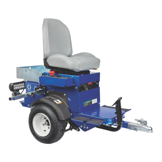
LineDriver
For the propulsion of line striping and removal equipment. Not approved for use in
explosive atmospheres or hazardous locations. For professional use only.
Models: 25N555, 25N556
10 mph (16 kph) Maximum Operating Speed
Important Safety Instructions
Read all warnings and instructions in this manual and in related LineLazer,
GrindLazer and ThermoLazer manuals before using the equipment. Save
these instructions.
Related Manuals:
710-0138
Delta-Q Battery Charger
3A6720
Hitch Receiver Kit
LineDriver ES
Model
Series
---
25N555
25N556
Use only genuine Graco replacement parts.
The use of non-Graco replacement parts may void warranty.
™
ES
Cord Adapter
B
North America
North America
Australia
CEE 7/7
B
Denmark
Italy
Switzerland
United Kingdom
3A6623D
EN
Advertisement
Table of Contents
Troubleshooting

Related Manuals for Graco LineDriver ES


Summary of Contents for Graco LineDriver ES
- Page 1 Delta-Q Battery Charger 3A6720 Hitch Receiver Kit LineDriver ES Model Series Cord Adapter 25N555 North America North America Australia CEE 7/7 25N556 Denmark Italy Switzerland United Kingdom Use only genuine Graco replacement parts. The use of non-Graco replacement parts may void warranty.
-
Page 2: Table Of Contents
Accelerator Calibration (Using Kit 25N880) . . . 15 Graco Information ......36 Transaxle Service ..... . . 17... -
Page 3: Warnings
Warnings Warnings The following warnings are for the setup, use, grounding, maintenance, and repair of this equipment. The exclamation point symbol alerts you to a general warning and the hazard symbols refer to procedure-specific risks. When these sym- bols appear in the body of this manual or on warning labels, refer back to these Warnings. Product-specific hazard sym- bols and warnings not covered in this section may appear throughout the body of this manual where applicable. - Page 4 Warnings BATTERY HAZARD Lead-acid batteries produce explosive gases and contain sulfuric acid that can cause severe burns. To avoid sparks and injury when handling or working with a lead-acid battery: • Only use the battery type specified for use with the equipment. See Technical Data. •...
-
Page 5: Component Identification
Component Identification Component Identification 14 Power Switch Headlight 15 Speed Switch Direction/Speed Pedals 16 ExactMil ™ Step Plate Speed Control Hitch 17 Voltage Meter Coupler 18 12V Aux. Power Safety Pin Location 19 Light Socket Handle Open 20 Motor Controller Diagnostic Light Handle Locked 21 Battery Charger Parking/Emergency Brake... -
Page 6: Setup
Setup Setup 1. Install supplied ramp onto pallet. 5. Insert safety pin in latch 2. Connect Hitch Receiver to line striping or line removal equipment - Hitch Receiver Kit 25N787; Manual 3A6720. ti11086a 6. Adjust seat forward/backward with lever below seat. ti11085a 7. -
Page 7: Startup
Startup Startup Know Your Controls Speed Switch ™ ExactMil (Speed Control) Mode Direction/Speed Pedals ExactMil Mode ensures a consistent paint thickness by The Direction/Speed Pedals drive the LineDriver forward holding the speed steady. To enable ExactMil mode: and in reverse. Switching from forward to reverse creates a braking action. -
Page 8: Daily Inspections
Single tone, about one Direction/Speed control second long, after pedals now active. turning the Power Switch b. Cause the LineDriver ES to roll freely (free- wheel) by moving the Power Switch to the OFF position. Repeating tone, about Batteries are deeply every second. -
Page 9: Operation
When the batteries are deeply discharged and the Turning the Power Switch OFF will result in loss of LineDriver ES is about to shut down, the buzzer drive power. Loss of drive power causes LineDriver to sounds about once per second. -
Page 10: Operating On Inclines
Park- ing/Emergency Brake when starting on an incline. Trailer Loading & Unloading NOTE: LineDriver ES rolls freely, especially on inclines, when the power is off. Set Parking/Emergency Brake before turning off. Turn power on before releasing Park- ing/Emergency Brake. -
Page 11: Charging The Batteries
Operation Charging the Batteries 3. Ensure Power Switch is in OFF position. Replace and charge battery only in well-ventilated area and away from flammable or combustible mate- rials, including paints and solvents. The charger may become hot while charging. Do not touch. Refer to Charger Manual for additional information. - Page 12 Operation 5. The Charging Output Indicator means that the char- NOTE: The Charge Display may show codes to indicate ger output is active. different conditions. Refer to charger manual for addi- tional information. 6. When power is connected, charger will immediately begin charging.
-
Page 13: Maintenance
Maintenance Maintenance Parking/Emergency Brake 5. Install two bolts and secure brake rod. Repeat for second tire. Adjustment or Replacement 1. Block tires so LineDriver will not move. Release Parking/Emergency Brake. 2. Ensure Power Switch is in OFF position. 3. Inflate tires to operating pressure per tire sidewall. Remove two bolts securing brake rod. -
Page 14: Throttle Linkage Adjustment
Maintenance Throttle Linkage Adjustment 3A6623D... -
Page 15: Coupler Adjustment
Maintenance Coupler Adjustment A Coupler too tight or too loose needs to be adjusted. Ensure Power Switch is in OFF position. Before adjusting, check ball and Coupler for wear. Replace entire Coupler if unable to tighten it. 3A6623D... -
Page 16: Accelerator Calibration (Using Kit 25N880)
Maintenance Accelerator Calibration (Using Kit 25N880) 1. Turn power OFF. Engage Parking/Emergency 8. Rotate accelerator arm back and forth, then return it Brake. to neutral position. Re-adjust voltage if necessary. Turn power OFF. 2. Slowly raise hitch Coupler until LineDriver rests on rear bumper. -
Page 17: Transaxle Service
Maintenance Transaxle Service Check Oil Level (Annually) 5. Reinstall plug. 1. Turn power OFF. Engage Parking/Emergency Change Oil (recommended every 3 years) Brake. 1. Turn power OFF. Engage Parking/Emergency 2. Slowly raise hitch Coupler until LineDriver rests on Brake. rear bumper. 2. -
Page 18: Repair
Repair Repair Battery Pack Replacement 6. Remove battery holders. Remove batteries and recycle according to below. NOTE: Prior to replacing batteries, use Troubleshoot- ing - LineDriver, page 20, to determine if the batteries are the cause of the problem. Also, use a battery load tester to confirm the batteries need replacement. -
Page 19: Transaxle Replacement
Repair Transaxle Replacement Motor Controller Replacement 1. Turn power OFF. 1. Turn power OFF. 2. Remove rear screws of Seat Lid. Pivot seat forward 2. Remove rear screws of Seat Lid. Pivot seat forward slowly. slowly. 3. Disconnect battery cables to motor controller. 3. -
Page 20: Troubleshooting - Linedriver
Troubleshooting - LineDriver Troubleshooting - LineDriver PROBLEM CAUSE SOLUTION Parking/Emergency Brake does not keep Line- Parking Brake needs adjustment Adjust Parking Brake Driver from moving Tire pressure too low Adjust pressure per tire sidewall LineDriver creeps in forward or reverse direction Throttle linkage too long or too short Adjust throttle linkage Head light does not turn on Connections... -
Page 21: Troubleshooting - Motor Controller
Troubleshooting - Motor Controller Troubleshooting - Motor Controller Diagnostics Summary of LED Display Formats Diagnostics information can be obtained by observing The two LEDs have four different display modes, indi- the fault codes issued by the Status LEDs. See Table 1 cating the type of information they are providing. - Page 22 Troubleshooting - Motor Controller NOTE: When a fault is encountered, shut off the Power Switch and turn it back on to see if the fault clears. If it does not, shut off the Power Switch and remove the 35-pin connector. Check the connector for corrosion or damage, clean if necessary, and re-insert connector.
- Page 23 Troubleshooting - Motor Controller CODE DESCRIPTION POSSIBLE CAUSE SET / CLEAR CONDITIONS SOLUTION Non-controller system Inspect all cables and connec- drain on battery. tors from batteries to control- Battery resistance too ler. Set: Battery pack voltage high. Let battery cool then fully dropped below the Severe Battery disconnected recharge battery.
- Page 24 Troubleshooting - Motor Controller CODE DESCRIPTION POSSIBLE CAUSE SET / CLEAR CONDITIONS SOLUTION Normal operation. Charge batteries. Fault indicates the bat- Let battery cool then fully teries need recharg- recharge battery. If error hap- ing. Controller is pens again, load test batteries performance limited at Set: Battery pack voltage and replace if needed.
- Page 25 Troubleshooting - Motor Controller CODE DESCRIPTION POSSIBLE CAUSE SET / CLEAR CONDITIONS SOLUTION Set: Motor phase U, V, or W Motor phase is open. Inspect U, V, W cables. detected open. Motor Open Bad crimps or faulty Replace motor. wiring. Clear: Cycle Power Switch.
-
Page 26: Parts Drawing
Parts Drawing Parts Drawing Torque cable cap screws or nuts to 7-8 ft-lbs (9-11 N·m) 3A6623D... -
Page 27: Parts Drawing
Parts Drawing Parts Drawing Torque to 8-9 ft-lbs (11-12 N·m) Torque to 40-60 ft-lbs (54-81 N·m) in criss-cross sequence Torque to 16-20 ft-lbs (22-27 N·m) Torque to 10-11 ft-lbs (14-15 N·m) Torque to 1.8-2.3 ft-lbs (2.5-3.2 N·m) 3A6623D... -
Page 28: Parts Drawing - Detail Views
Parts Drawing - Detail Views Parts Drawing - Detail Views Torque to 6-7 ft-lbs. (8-9 N·m) Torque to 20-25 ft-lbs (27-34 N·m) Torque to 90-115 ft-lbs (122-156 N·m) Torque to 95-105 in-lbs (10.7-11.9 N·m) Use a wrench to support backup nuts firmly while tightening. -
Page 29: Parts Drawing
Parts Drawing Parts Drawing Clamped parts must move freely after tightening 3A6623D... -
Page 30: Parts List
Parts List Parts List Ref. Part Description Ref. Part Description 100521 SCREW, cap, hex head 25N649 FRAME, electric LineDriver 111040 NUT, lock, insert, nylock, 5/16 15N470 PLATE, floor 25N471 CARRIAGE 25N776 KIT, throttle, includes 180 25N476 LID, seat, paint 15R872 INSERT, bearing, flange 100424 SCREW, cap, hex hd 116887 BEARING, flanged, bronze 801020 NUT, lock, hex... - Page 31 17Z073 KIT, terminal, block 114425 BUSHING, strain relief 25N762 KIT, transaxle, assembly, includes 41, 42, 45 15R308 CORD, power 25N778 KIT, LineDriver ES light 15R864 KNOB 25N787 KIT, hitch 111800 SCREW, cap, hex hd 161a 17Z155 BRACKET, hitch mount 111930 SWITCH, toggle...
-
Page 32: Wiring Diagram - Harness 25N661
Wiring Diagram - Harness 25N661 Wiring Diagram - Harness 25N661 3A6623D... -
Page 33: Wiring Diagram
Wiring Diagram Wiring Diagram 3A6623D... -
Page 34: Wiring Diagram - Harness 25E406
Wiring Diagram - Harness 25E406 Wiring Diagram - Harness 25E406 3A6623D... -
Page 35: Technical Specifications
Technical Specifications Technical Specifications LineDriver ES U.S. Metric Dimensions Height 48.5 in. 1232 mm Width 29.3 in. 744 mm Length 58.2 in. 1478 mm Weight 620 lbs. 281 kg Speed Forward 0-10 mph 0-16 kph Reverse 0-6 mph 0-10 kph... -
Page 36: Graco Standard Warranty
With the exception of any special, extended, or limited warranty published by Graco, Graco will, for a period of twelve months from the date of sale, repair or replace any part of the equipment determined by Graco to be defective.
Need help?
Do you have a question about the LineDriver ES and is the answer not in the manual?
Questions and answers