
Related Manuals for Red Heating PERFORMA 15 EasyClean Plus


Summary of Contents for Red Heating PERFORMA 15 EasyClean Plus
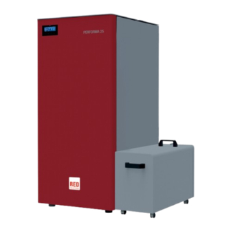
- Page 1 INSTALLATION GUIDE PELLET BOILER PERFORMA 15 EasyClean Plus PERFORMA 20 EasyClean Plus PART 2 - OPERATION AND CLEANING Instructions in English...
-
Page 2: Table Of Contents
TABLE OF CONTENTS TABLE OF CONTENTS ....................II 12-CONTROL PANEL ....................3 13-FIRST START-UP .....................4 14-MENU STRUCTURE ....................8 15-INFORMATION MENU ...................11 16-SETTINGS MENU ....................14 17-TECHNICAL MENU ....................31 18-SAFETY DEVICES AND ALARMS ................32 19-RECOMMENDATIONS FOR SAFE USE ...............38 20-CLEANING AND MAINTENANCE................39 21-FAULTS/CAUSES/SOLUTIONS .................46 22-CIRCUIT BOARD ....................49... -
Page 3: 12-Control Panel
12-CONTROL PANEL CONTROL PANEL DISPLAY MENU A - DISPLAY; indicates a series of information on the boiler, as well as the identification code of any malfunction. B - Function selection key indicated by the upper display (i.e. start-up/shutdown) C - Function selection key indicated by the upper display (i.e. increase/scrolling) D - Function selection key indicated by the upper display (i.e. -
Page 4: 13-First Start-Up
13-FIRST START-UP FIRST START-UP REV.SOFTWARE NUM BANCA DATI At initial start-up, after connecting the power cable and pressing the I/O button, the boiler display will show wording for the software version and database number (after a few seconds it will move on to the next screen). If the language has already been set, the next screen will be OFF, otherwise one enters the following parameter. - Page 5 13-FIRST START-UP SCREEN OFF If a LANGUAGE has already been set, the display will go to OFF. By pressing any one of the keys (B, C, D, E) the first screen will appear with the wording OFF displayed. From this screen, pressing keys “B” and “E”...
- Page 6 13-FIRST START-UP Start-up To switch on the boiler, keep the “B” (ON) key on the panel pressed. The boiler starts an ignition procedure that brings the flame to a suitable level to Supply Power. 10:13 TIMER1 23° 25° OFF 63° TEMP MENU Supplying power...
- Page 7 13-FIRST START-UP TEMPERATURE Press the “D” TEMP button (see the image on the previous page) to set the temperature of the heating and possibly the domestic water (if the storage cylinder with probe is configured - see the menu settings input aux). Select what is to be set and then using the C and D keys increase/decrease the temperature, use the E key to confirm while the B key is used to exit and return to the main MENU.
-
Page 8: 14-Menu Structure
14-MENU STRUCTURE MENU STRUCTURE To enter MENU press the “E” key (MENU). 10:13 TIMER1 23° 25° OFF 63° TEMP MENU Next, this screen with the following functions is displayed: FUNCT. PROGRAMAS Sub-menu INFORMATION SETTINGS FUNCTIONS EXIT PROGRAMMES INFORMATION SETTINGS PROGRAMMES In this case it is possible to choose the programme to be set. - Page 9 14-MENU STRUCTURE In the MENU screen, move the cursor with arrows “C”-”D” and select PROGRAMS, press ok “E” to confirm. Next select the programme you wish to set. Once completed, always press “ACTIVATE” to confirm the choice of programme. The TIMER 1 and 2 programs are freely programmable for each 1/2 hour of the day on three different temperature indicators (T1-T2-T3) and in different ways for each day of the week.
- Page 10 14-MENU STRUCTURE MANUAL This function can be activated from the menu PROGRAMME by pressing the key “C” ACTIVE. When this function is activated, the boiler no longer follows time programming of TIMER 1 or 2 programs, but it keeps the temperature set in the main screen throughout the 24-hour time period.
-
Page 11: 15-Information Menu
15-INFORMATION MENU INFORMATION To enter the INFORMATION menu, proceed as follows: from the main/initial screen, press the “E” Menu button, scroll using the “D” arrow key, up to the Information item, press the “E” ok key, scroll again using the “D” arrow key up to software/data memory/all.memory/boiler state and select the desired item, press OK using the “E”... - Page 12 15-INFORMATION MENU DATA MEMORY-INFORMATION INFORMATION-DATA HYSTORY WORKING HOURS = 100 TOTAL IGNITIONS = 20 TEST DATE = 15/01/2013 EXIT The available data in this function are: WORKING HOURS TOTAL IGNITIONS TEST DATE ALARM MEMORY-INFORMATION It gives information about the last alarms detected. INFORMATION-ALARM HYSTORY ALARM 02 - 28/06/13 13:44 1 ALARM 02 - 21/06/13 08:03 2...
- Page 13 15-INFORMATION MENU BOILER STATE-INFORMATION This menu is particularly useful if you want to verify the boiler’s working condition (State). From the OFF screen, press the “E” Menu button, scroll with the “D” arrow key, up to the Information item, press the ok “E” key, scroll again with the “D”...
-
Page 14: 16-Settings Menu
16-SETTINGS MENU SETTINGS To enter the menu SETTINGS, proceed as follows: from the OFF screen, press the “E” Menu key, scroll with the “D” arrow key up to Settings item, press the ok “E” key, scroll again with the “D” and/or “C”... - Page 15 16-SETTINGS MENU AUTOECO (factory activated) SETTINGS-AUTOECO IF YOU ACTIVATE THE AUTOECO, DEACTIVATE ACTIVATE THE STOVE GOES OFF WHEN THERE AUTOECO AUTOECO ARE NO MORE HEAT REQUESTS INFO EXIT The Auto eco mode turns the boiler off when heating the system does not require heat, depending on the menu-settings-input aux configuration.
- Page 16 16-SETTINGS MENU FEED SCREW LOADING (only with the boiler off) SETTINGS-FEED SCR LOAD USE THE 'FEED SCREW LOADER' WHEN DEACTIVATE ACTIVATE THE FEED SCREW IS EMPTY AND LOAD LOAD YOU MUST LOAD IT QUICKLY INFO EXIT This function is for filling the pellet loading system. It can only be activated with the boiler off. To enter the function: from the Settings menu - press ok (E key), press the D key (arrow key) and scroll up to load feed screw, press OK (E key) and activate/ deactivate the function, press ok (“E”...
- Page 17 16-SETTINGS MENU PELLET RECIPE SETTINGS-LOAD-RECIPE CHANGE BY PERCENT THE FEED SCREW +15% SPEED TO ADAPT THE STOVE TO THE TYPE OF PELLET INFO EXIT This function is for adapting the boiler to the type of pellet in use. As there are many types of pellet available on the market, boiler operation can vary considerably according to the quality of the fuel.
- Page 18 16-SETTINGS MENU CLEANING CYCLE SETTINGS-CLEANING IMMEDIATELY ACTIVATE A CLEANING DEACTIVATE ACTIVATE CYCLE OF THE BRAZIER CLEANING CLEANING INFO EXIT This function can only be activated with the boiler in OFF supply: from the Settings menu- press ok (E key), press the D key (arrow key), scroll up to the “ciclo pulizia” (cleaning cycle) press OK (E key)- Activate/deactivate cleaning.
- Page 19 16-SETTINGS MENU AUX INPUT (using one of the following parameters excludes the other) The auxiliary input allows you to choose the system configuration type based on which the boiler is connected. To enter the function press: from the Settings menu- press ok (E key), press the D (arrow) key and scroll up to the Aux Input item and press OK (E key). Using the “C” and “D”...
- Page 20 16-SETTINGS MENU • External probe It makes it possible to work with system temperature adjustment. If installing an external probe on terminals 1 and 2 (NTC 10KOhm at 25°C b=3435) water temperature is automatically calculated by the electronics based on external temperature according to the curves shown below: The external probe must be installed on an external wall exposed towards North or North-West.
- Page 21 16-SETTINGS MENU • Puffer thermostat To activate this option, connect a Normally Open (N.O.) contact thermostat to points 1 and 2 of the back 12-pole terminal board. Even with this configuration the purpose of the room probe on the boiler is only to control the heating system pump controlled by the potential free contact on terminals 7-8-9, if the system pump is activated in Aux out mode.
- Page 22 16-SETTINGS MENU BOILER PRINCIPLE DIAGRAMS The following diagrams are to be used only as a guideline. For proper connection, always follow the notes of the plumbing and heating installer. The plumbing system must meet local, regional, or national regulations in force.
- Page 23 16-SETTINGS MENU SYSTEM WITH: DIRECT PELLET BOILER AND DHW BOILER Set settable VALUES WATER TEMP 60° C - 80°C BOILER TEMP. 10°C - 70°C Parameters to be set Settings Value AMB Input Room thermostat AUX Input Boiler Probe AUX Output None Hydraulic diagram Num.
- Page 24 16-SETTINGS MENU SYSTEM WITH: PELLET BOILER, PUFFER AND BOOSTER PUMP Set settable VALUES STORAGE TEMP. 50°C - 80°C Parameters to be set Settings Value AMB Input Room Thermostat AUX Input Puffer Probe AUX Output Puffer Pump Hydraulic diagram Num. Description Num.
- Page 25 16-SETTINGS MENU SYSTEM WITH: PELLET BOILER, PUFFER AND EMERGENCY BOILER (WALL-MOUNTED) Set settable VALUES STORAGE TEMP. 50°C - 80°C Parameters to be set Settings Value AMB Input None AUX Input Puffer Probe AUX Output Auxiliary boiler Hydraulic diagram Num. Description Num.
- Page 26 16-SETTINGS MENU SYSTEM WITH: PELLET BOILER, PUFFER AND DHW BOILER Set settable VALUES STORAGE TEMP. 50°C - 80°C BOILER TEMP. 10°C - 70°C Parameters to be set Settings Value AMB Input Puffer Probe AUX Input Boiler Probe AUX Output None Hydraulic diagram Num.
- Page 27 16-SETTINGS MENU OUTPUT AUX SETTINGS-OUTPUT AUX SET AMBIENT INPUT: REMOTE BOILER ALLARM IN T = (TERMINALS 3 - 4) INFO EXIT The AUX output makes it possible to use a relay contact, based on the system configuration type chosen in the Aux Input menu. It acts on contact 7-8-9 of the external terminal board: •...
- Page 28 16-SETTINGS MENU INPUT AMB SETTINGS - INPUT AMB SET AMBIENT INPUT: AMB PROBE THERM.AMB (TERMINALS 3 - 4) INFO EXIT The room input is used to set the probe or the thermostat at terminals 3-4 of the back terminal board of the boiler. The boiler has the room probe set as default factory settings.
- Page 29 16-SETTINGS MENU PWM PUMP This function is used to set high efficiency pump speed. To enter the function press: from the Settings menu- press ok (E key), press the C-D key (arrow) and scroll up to PWM Pump, press OK (E key)- Modify the percentage using the central C and D keys, press the E key to confirm.
- Page 30 16-SETTINGS MENU DISPLAY SETTINGS-DISPLAY CONTRAST BRIGHTNESS Adjust display contrast and brightness. This function is found in: from the Settings menu- press ok (E key), press the C-D key (arrow) and scroll up to Display, press OK (E key)- Modify the settings using the B - C - D keys and press the E key to confirm.
-
Page 31: 17-Technical Menu
17-TECHNICAL MENU TECHNICAL MENU To access the technical menu you must contact the service centre as it requires a password. To make changes in the technical menu, enter the SETTINGS menu, press the “E” (OK) key, scroll using the “C”-”D” arrows keys and select Technical menu and press OK (E key)- Enter the password and press the E key to confirm. -
Page 32: 18-Safety Devices And Alarms
18-SAFETY DEVICES AND ALARMS SAFETY DEVICES The product is fitted with the following safety devices ACTIVE + Besides adjusting the boiler operation, it also guarantees that the pellet loading feed screw is blocked if unloading is blocked or there is significant back pressure. - Page 33 18-SAFETY DEVICES AND ALARMS TAMPERING WITH THE SAFETY DEVICES IS PROHIBITED If the boiler is NOT used as described in this instruction manual, the manufacturer declines all responsibility for damage to persons and property that may arise. The manufacturer furthermore refuses to accept responsibility for damage to persons and property arising from the failure to observe all the rules contained in the manual and in particular: •...
- Page 34 18-SAFETY DEVICES AND ALARMS ALARM ALERTS If there is an operational anomaly, the boiler enters the alarm phase displaying the problem that has taken place through a code, a brief description of the alarm type and an acoustic warning. The following table describes the possible alarms indicated by the boiler, associated to the respective code that appears on the panel and helpful tips to solve the problem.
- Page 35 18-SAFETY DEVICES AND ALARMS WRITTEN ON THE TYPE OF PROBLEM SOLUTION DISPLAY Check that the lower compartment is clean (see the pages dedicated to boiler cleaning) and verify that it is Faulty smoke fan. not obstructed; clean it and cancel the alarm. FLUE GAS FAN If the alarm persists, contact the service centre.
- Page 36 18-SAFETY DEVICES AND ALARMS WRITTEN ON THE TYPE OF PROBLEM DISPLAY SOLUTION Possible obstruction in the brazier. Clean. Brazier not closed If the problem persists, contact a service centre. Possible fault in the safety component. Contact an authorised service centre to have the component Room probe failure checked and, if needed, replace the component.
- Page 37 18-SAFETY DEVICES AND ALARMS SHUTDOWN If the shut-down key is pressed or one of the following conditions occurs: • power request ends (Power = 0) for Ecostop, Timer, Sleep • an alarm condition occurs • water overheating occurs the boiler enters the shutdown and thermal cooling phase that automatically includes the execution of the following phases: •...
-
Page 38: 19-Recommendations For Safe Use
19-RECOMMENDATIONS FOR SAFE USE ONLY CORRECT INSTALLATION AND APPROPRIATE MAINTENANCE AND CLEANING OF THE APPLIANCE CAN GUARANTEE CORRECT OPERATION AND SAFE USE OF THE PRODUCT We would like to inform you that we are aware of cases of malfunctioning of domestic pellet-fuelled heating products, mainly due to incorrect installation and inappropriate maintenance. -
Page 39: 20-Cleaning And Maintenance
20-CLEANING AND MAINTENANCE Disconnect the product from the 230V power supply before performing any maintenance operations. DAILY OR WEEKLY CLEANING PERFORMED BY THE USER If the pellets in the tank run out, unburned pellets may accumulate in the brazier. Check the status of your brazier every 15 days. The automatic cleaning system means you don’t have to empty the brazier. - Page 40 20-CLEANING AND MAINTENANCE CLEANING THE TROLLEY Red recommends checking the level of the ash inside the trolley every 30 days with the boiler switched off and in any case empty the container every two months(*). Carry out this check as follows: •...
- Page 41 20-CLEANING AND MAINTENANCE When emptying the trolley, thoroughly clean the top and bottom auger compartment with the vacuum cleaner nozzle. AUTOMATIC CLEANING The boiler is equipped with a series of devices that facilitate the automatic cleaning operations of the product. Please note that these devices are not substitutes to the normal routine cleaning operations (brazier cleaning, trolley emptying and cleaning of lower augers with vacuum cleaner).
- Page 42 20-CLEANING AND MAINTENANCE PERIODIC CLEANING PERFORMED BY A QUALIFIED TECHNICIAN CLEANING THE SMOKE EXTRACTOR COMPARTMENT This operation must be performed by a technician, authorised once per season. To do this cleaning it is necessary to disassemble the lower augers, this is why we recommend the intervention of a technician. LOWER COMPARTMENT CLEANING...
- Page 43 20-CLEANING AND MAINTENANCE CLEANING THE SMOKE EXPULSION SYSTEM AND GENERAL CHECKS Clean the smoke outlet system, especially around the “T” joints, elbows and any horizontal sections of the smoke duct. For information on periodically cleaning the flue, contact a skilled chimney sweep. Check the integrity of the ceramic fibre seals on the door of the boiler.
- Page 44 20-CLEANING AND MAINTENANCE REPLACING THE OVERPRESSURE DISCHARGE FOR THE COMBUSTION CHAMBER Overpressure rubber bushing “G” of the combustion chamber (fig. A) may get worn and/or damaged, it is therefore necessary to replace it once a year to ensure correct system operation. To replace it, follow the instructions below •...
- Page 45 20-CLEANING AND MAINTENANCE CHECKING THE INTERNAL COMPONENTS ATTENTION! The internal electromechanical components must only be checked by qualified personnel whose technical expertise includes combustion and electricity. We recommend that an annual maintenance service is carried out (with a scheduled service contract). This service is essentially a visual and functional inspection of the internal components.
-
Page 46: 21-Faults/Causes/Solutions
21-FAULTS/CAUSES/SOLUTIONS ATTENTION: All repairs must be carried out exclusively by a specialised technician, while the boiler is completely cold and the electric plug is disconnected. ANOMALY POSSIBLE CAUSES SOLUTIONS The pellets are not fed into the combustion The pellet hopper is empty Fill the tank with pellets chamber. - Page 47 21-FAULTS/CAUSES/SOLUTIONS ANOMALY POSSIBLE CAUSES SOLUTIONS The product works for a few minutes and Start-up phase is not completed Repeat start-up then switches off Temporary power cut Wait for the automatic restart Clogged smoke duct Clean the smoke duct Faulty or malfunctioning temperature Check and replace the probes probes Pellets accumulate in the brazier, the glass...
- Page 48 21-FAULTS/CAUSES/SOLUTIONS ANOMALIES RELATED TO THE HYDRAULIC CIRCUIT ANOMALY POSSIBLE CAUSES SOLUTIONS Incorrect combustion adjustment. Check recipe No increase in temperature with stove in operation Boiler / system dirty. Check and clean the product Insufficient appliance power Check that the appliance is properly sized for the requirements of the system Poor pellet quality Using pellets from the producer...
-
Page 49: 22-Circuit Board
22-CIRCUIT BOARD 13 14 15 MOTHERBOARD WIRING KEY AUX RELAY (C-NO-NC) 15. PWM PUMP CONTROL HOME AUTOMATION CONTACT 16. CONTROL PANEL ROOM PROBE 17. WATER TEMPERATURE OVERLOAD CUT-OUT AUX INPUT 18. HOPPER OVERLOAD CUT-OUT SMOKE FAN ENCODER 19. BRAZIER CLEANING GEAR MOTOR ENCODER 20. - Page 52 Via La Croce n°8 33074 Vigonovo di Fontanafredda (PN) – ITALY Telephone: 0434/599599 a.s. Fax: 0434/599598 Internet: www.red-fire.it e-mail: info@red-fire.it 8902003800 REV 0 27/02/2020...
Need help?
Do you have a question about the PERFORMA 15 EasyClean Plus and is the answer not in the manual?
Questions and answers