Table of Contents
Advertisement
ACiQ WIRED REMOTE CONTROLLER
Installation and Owner's Manual
MODEL:
KJR-120N(X4)/BGEF
KJR-120N(X6)/BGEF
KJR-120N(X4W)/BGEF
KJR-120N(X6W)/BGEF
KJR-120N(X5)/BGEF
KJR-120N(X5W)/BGEF
IMPORTANT NOTE:
Please read this manual carefully
before installing or operating your
wired remote controller. Make sure to
save this manual for future reference.
Advertisement
Table of Contents

Related Manuals for ACIQ KJR-120N(X4)/BGEF


Summary of Contents for ACIQ KJR-120N(X4)/BGEF
- Page 1 ACiQ WIRED REMOTE CONTROLLER Installation and Owner’s Manual MODEL: KJR-120N(X4)/BGEF KJR-120N(X6)/BGEF KJR-120N(X4W)/BGEF KJR-120N(X6W)/BGEF KJR-120N(X5)/BGEF KJR-120N(X5W)/BGEF IMPORTANT NOTE: Please read this manual carefully before installing or operating your wired remote controller. Make sure to save this manual for future reference.
- Page 2 All the pictures in this manual are for explanation purposes only. There may be slight differences due to future improvements. Contact ACiQ if you are unable to use the thermostat as described here.
-
Page 3: Table Of Contents
Table of Contents .....1 1. Safety precautions 2. Installation accessories ....2 ....4 3. Installation 4. Specifications ....12 ..,,....13 5. Features and functions 6. Display Definitions ....14 7. Buton Definitions ....15 8. Setup ....16 ....17 9. Operation 10. Timer functions ....27 ....30 11. -
Page 4: Safety Precautions
1. Safety precautions WARNING • Be sure to have this equipment professionally installed. • Installation by non-professionals may lead to improper performance, electric shock or fire. • Follow this installation manual carefully. Service or repair should be performed by professionals. •... -
Page 5: Installation Accessories
Safety precautions NOTE Use correct wire gauge. Do not over tighten terminal screws. • If the wire is cut due to over-tightening, restrip wire and start again to avoid overheating at the connection. 2. Installation Accessories Checklist 1. Please confirm that all the following parts were included. Name Qty. - Page 6 2. Installation accessory 2. Checklist. Specification Qty.(embeded Remarks Name (only for reference) into wall) Thermostat base Wire harness Thermostat wiring 1. Please refer to the wiring diagram of this installation manual to connect the wire controller with indoor unit. 2. The wired controller works in low voltage loop circuit. Do not connect this unit to 24v, or high voltage (115V,220V).
-
Page 7: Installation
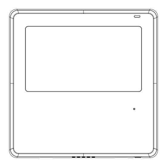
3. Installation 1.Wired remote controller structural dimensions .75" 4.75" 1.875" Fig 3-1 2.375" 2. Remove the case from the thermostat Buckling Back cover Insert a flat blade screwdriver into position the slots in the lower part of the wired controller (2 places), and twist to release tabs. - Page 8 3. Installation NOTE: Be careful not to damage the circuit board or other internal components with the screwdriver when opening the case. 3. Fasten the back plate of thermostat For wakk mounting, fasten the back plate on the wall with the 3 screws (ST3.9*25) and anchors.
- Page 9 3. Installation NOTE: Use a flat wall surface for installation location. Be careful not to overtighten the mounting screws. 4. Battery installation Fig 3-5 Install the battery making sure the polarity of the battery is in accordance with the +/- indication. (See Fig.3-5) The CR2032 battery insures the thermostat will keep time and maintain program settings during a power failure.
- Page 10 3. Installation 5. Wire to the indoor unit 2.375" hole Model A 60mm hole Model B Fig 3-6...
- Page 11 3. Installation Model A Use the included wires to connect the indoor unit to the thermostat as shown. Note there may be unused connections. Mainboard 4-core wire Wire harness shielded wire(some units) Fig 3-7 Ducted or ceiling cassette air handler Adaptor board Display board 4-core wire...
- Page 12 3. Installation 2-wire model 1 indoor unit Notch the case for the wiring to pass through with nippers, if needed. Connect the terminals on the wired controller (HA ,HB), and the terminals of the indoor unit (HA ,HB). (HA and HB do not have polarity.) NOTE: Keep water away from thermostat.
- Page 13 3. Installation The main/secondary wired controller can be used to enable two wired controllers to control one unit, and the wired controllers connect to the unit HA and HB ports through the HA and HB port on the controller. There is no polarity between HA and HB.
- Page 14 3. Installation unit need to be connected to the HA and HB ports at the same time. In group control, there will be no error displayed on the wired controller . SeeFig. 3-11 Indoor Unit 1 Indoor Unit 2 Indoor Unit n (n<=16) HA HB HA HB...
-
Page 15: Specifications
6. Reattach the thermostat case Place the case on the upper mounts, then carefully click into place, being careful not to pinch the wiring. (Fig 3-13) All the pictures in this manual are for explanation purpose only. Your thermostat may be slightly different . -
Page 16: Features And Functions
5. Thermostat features and functions. Features: LCD display. Error code display: displays the error code for service. 4-way wire layout design - gives extra room for wiring for easy installation. Room temperature display. Weekly Timer. Functions: Mode: Choose Auto-Cool-Dry- Heat -Fan Auto-restart Fan speed: Auto/Low/Med/High speed Individual louver control... -
Page 17: Display Definitions
6. Display Definitions °C / °F display MODE display Temperature display Room temperature display Displays the current mode,including: Relative humidity display Lock display Wireless control feature display Follow me feature display Breeze away display Delay off display Turbo feature display ECO feature display Purify feature display Filter reminder display... -
Page 18: Buton Definitions
7. Button Definitions 1 FAN SPEED button 7 COPY button 2 MODE button 8 POWER button 3 FUNC. button 9 CONFIRM button 4 SWING botton 10 BACK button 5 ADJUST button 11 DAY OFF/DELAY button 6 TIMER button 12 CHILD LOCK button... -
Page 19: Setup
8. Setup Set the current day and time Press the Timer button for 2 seconds or more. The timer display will ash. Press the button “ ” or “ ” to set the date. The selected date will ash. After entering Date, press Timer button or CONFIRM button or wait 10 seconds. -
Page 20: Operation
Time scale selection Press the buttons “ ” and “ ” for 2 seconds will alternate the clock time display between 12h & 24h scale. 9. Operation To start/stop operation Press the Power button. - Page 21 9. Operation To set the operation mode Operation mode setting(Heat mode is invalid for cool only type unit) Press this button to select the operation mode: If the indoor unit has Electric heating (Emergency heating) feature, press this button to select the operation mode: When the mode is selected as emergency heating (or electric heating) mode, is displayed, the fan speed is Auto.
- Page 22 9. Operation Room temperature setting Press the button“ ”or “ ” to set the room temperature. Lower Indoor Setting Temperature Range : (50/60/62~86°F ) or (68~82°F ). Raise (Model dependent) °C & °F scale selection (on some models) Press the buttons “ ”...
- Page 23 9. Operation Child lock function Press the buttons “ ” and “ ” for 3 seconds to activate the child lock function and lock all buttons on the wire controller. You can't press the button to operate or receive remote control signals after the child lock is activated.
- Page 24 9. Operation Swing function (For units without vertical swing function ) Use Swing button to adjust the Up-down air ow direction and start the auto swing function. 1.Each time you press this button, the louver swings an angle of 6 degrees. Press this button until the desired direction reaches.
- Page 25 9. Operation 3. Next use the Swing button to adjust the Up-Down airflow direction of the selected louver. Press the FUNC. button to scroll through operation functions as followings: [ ]: Model dependent. If the indoor unit has no this function, it will not display.
- Page 26 9. Operation Intelligent eye display (certain models only) 1. This function is valid in any mode of power-on state. 2. If your thermostat has smart eye, press the function key to select the smart eye icon, press the OK key to turn on the smart eye. The smart eye icon will display.
- Page 27 9. Operation Humidity setting function 1. If your model has both temperature and humidity, in dehumidification mode, press the function key to select the RH icon, press the confirm key to enter the humidity control mode, the RH icon flashes, press the up and down keys to adjust the humidity, the setting range is OFF->35%~85%, adjusted with 5% humidity.
- Page 28 9. Operation GEAR function (certain models) 1. If your model has the GEAR function, in boot cooling mode, press the function key to select the GEAR icon, press the confirm key to enter the GEAR control mode. First the display will show the current GEAR status.
- Page 29 9. Operation This page is intentionally blank.
-
Page 30: Timer Functions
10. Timer functions WEEKLY timer Use this timer function to set operating times for each day of the week. On timer Use this timer function to start air conditioner operation. The timer operatesand air conditioner operation starts after the time has passed. O timer Use this timer function to stop air conditioner operation. - Page 31 10. Timer functions To set the On or Off TIMER Press the Timer button to select the No display Press the Con rm button and the Timer display is ashing. ex.O timer set at 18:00 Press the button “ ” or “ ”...
- Page 32 10. Timer functions To set the On and Off TIMER Press the Timer button to select the Press the Con rm button and the Clock display is ashing. Press the button “ ” or “ ” to set the time of On timer, and then press the Con rm button to con rm the setting.
-
Page 33: Weekly Timer 1
11. Weekly Timer 1 Weekly timer setting Press the Timer button to select the and then press the Con rm button to con rm. Day of the week setting Press the button “ ” or “ ” to select the day of the week and then press the Con rm button to con rm the setting. - Page 34 11. Weekly Timer 1 ex.Tuesday time scale 1 Up to 4 timer settings can be saved for each day of the week. Off timer setting of timer setting 1 Press the button “ ” or “ ” to set the time of O timer and then press the Con rm button to con rm the setting.
- Page 35 11. Weekly Timer 1 WEEKLY timer operation To activate WEEKLY TIMER operation Press the Timer button while is displayed on the LCD. To deactivate WEEKLY TIMER operation Press the Timer button again will disappear from the LCD. To turn off the air conditioner during the weekly timer 1.
- Page 36 11. Weekly Timer 1 To set the DAY OFF (temporary change to timer) During the weekly timer, press the Con rm button. Press the button “ ” or “ ” to select the day in this week . Press the Day o button to set the DAY OFF. mark is hidden ex.The DAY OFF is set for Wednesday The DAY OFF can be setted for other days by repeating...
- Page 37 11. Weekly Timer 1 DELAY function While in weekly timer, press the FUNC. button , select the delay function and press the Con rm button,display" " " "" " and wait 3 seconds to con rm. When the delay function is activated,the “ ”mark appears.
- Page 38 11. Weekly Timer 1 Press the Copy button,the letter “CY” will be shown on the LCD. Press the button “ ” or “ ” to select the day to copy Press the Copy button to con rm . mark ashes quickly ex.
-
Page 39: Weekly Timer 2
11. Weekly Timer 2 Weekly timer setting Press Timer to select the and press Con rm. Day of the week setting Press “ ” or “ ” to select the day of the week and then press CONFIRM. ON timer setting of timer setting 1 Press “... - Page 40 12. Weekly Timer 2 IMPORTANT: Up to 8 scheduled events can be set on one day. Various events can be scheduled in either MODE, TEMPERATURE and FAN speeds. ex.Tuesday time scale 1 Time setting Press “ ” or “ ” to set the time, then press CONFIRM.
- Page 41 12. Weekly Timer 2 Fan speed setting Press “ ” or “ ” to set the fan speed then press CONFIRM. NOTE: This setting is unavailable in the AUTO, DRY or OFF modes. Different scheduled events can be set by repeating steps 3 through 7.
- Page 42 12. Weekly Timer 2 WEEKLY timer operation To start Press Timer to select the , and then the timer starts automatically. To cancel Press the Power buttons for 2 seconds to cancel the timer mode. The timer mode can also be canceled by changing the timer mode using Timer.
- Page 43 12. Weekly Timer 2 Press DAY OFF to create an o day. mark is hidden ex.The DAY OFF is set for Wednesday Set the DAY OFF for other days by repeating the steps 2 and 3. Press BACK to revert to the weekly timer. To cancel, follow the same procedures used for setup.
- Page 44 12. Weekly Timer 2 Press “ ” or “ ” to select the day to copy from. Press COPY, the letters CY appear on the LCD. Press “ ” or “ ” to select the day to copy to. Press COPY to con rm. mark ashes quickly ex.
- Page 45 12. Weekly Timer 2 Delete timer settings for one day of the week. During the weekly timer setting, press CONFIRM. Press “ ” or “ ” to select the day of the week and then press CONFIRM. Press “ ” or “ ”...
-
Page 46: Troubleshooting
13. Troubleshooting See below for error codes and suggested resolution. D ISPLAY Error Code Definition D IGITAL TU BE Error of communication between wire controler and indoor unit The error displayed on the thermostat are different from those on the unit. If error code appears, please check the <<Owner’s And Installation Manual>>and<<SERVICE Manu- al>>. -
Page 47: Function Settings
15. Function settings To enter setup mode, press “COPY” for 3 seconds. The first display you see is P:00, which identifies the first air handler. If connected to multiple indoor units, press to display P:01, P:02, and then press “Confirm” to select indoor unit. Display now shows Tn (T1~T4) temperature and fan fault(CF), press“... - Page 48 15. Function settings Follow me function temperature compensation With the air conditioning unit off, enter setup mode, press “ ”or “ ”to select tF. The compensation temperature Range : -5~5°C. Press “Confirm” to make changes, press“ ”or “ ”to select the temperature, then press “Confirm”...
- Page 49 15. Function settings Set the highest and lowest temperature values With the air conditioner off, enter setup mode press“ ”or “ ”to select tHI or tLo. Press “Confirm” to make changes, press“ ”or “ ”to select the temperature, then press “Confirm” again to save changes. The highest setting temperature range : 25~30°C The lowest setting temperature range: 17 ~24°C.
- Page 50 15. Function settings Two - line controller address selection With the air conditioner off, enter setup mode, press“ ”or “ ”to select Adr. The temperature zone will display -- or A, B. Where -- refers to the code setting of the thermostat. Press “Confirm”...
- Page 51 15. Function settings After the wire controller resumes the factory parameter setting, the rotating parameter setting is restored to 10 hours (the highest and lowest temperature are not set); The compensation of body temperature is uncompensated; COOL and HEAT/single COOL mode is restored to COOL and HEAT model;...
-
Page 52: Wificontrol Connection
16.WiFicontrol connection SAFETY PRECAUTION Read the safety precautions carefully before installing the unit. Stated below are important safety issues that must be obeyed. Applicable system: IOS, Android. (Suggest: IOS 9.0 and above, Android 6.0 and above.) NOTE: Due to frequent OS upgrades , not all Andriod and IOS systems are compatible with APP. - Page 53 16.WiFi control connection CAUTION Please Check The Service Website For More Information. • Smart Phone camera needs to be 5 million pixels or above • to make sure scan QR code well. Due to different networks, sometimes network time-out • errors can occur.
- Page 54 16.WiFi control connection DOWNLOAD AND INSTALL APP On an app market (Google Play Store, Apple App Store), search for "NetHome Plus" and nd the NetHome Plus app. Download and install it on your phone, You can also download the app by scanning the QR code below.
- Page 55 16.WiFi control connection NETWORK CONFIGURATION CAUTION It is necessary to forget any other around network and • make sure the Android or IOS device just connect to the Wireless Network you want to con gure. Make sure the Android or IOS device Wireless Network •...
- Page 56 16.WiFi control connection Network configuration by Bluetooth scan Note: Make sure the bluetooth of your mobile device is working. Press “Scan for nearby Press “ + Add Device ” devices”...
- Page 57 16.WiFi control connection Select your network, Wait to find smart devices, enter the password then click to add...
- Page 58 16.WiFi control connection Configuration Success, Wait for network you can modify the default connection name.
- Page 59 16.WiFicontrol connection You can choose an Bluetooth network existing name or configuration is successful, customize a new name. now you can see the device in the list.
- Page 60 16.WiFi control connection NOTE: · Make sure your devices are powered on. · Keep your mobile phone close enough to your device when you are connecting network to your device. · Connect your mobile phone to the wireless network at home, and make sure you know the password of the Wireless Network.
- Page 61 16.Wireless control connection APP DECLARATION Hereby, we declare that this Smart kit is in compliance with the essential requirements and other relevant provisions of Directive 2014/53/EU. A copy of the full DoC is attached.(European Union products only) CAUTIONS: WirelessNetwork module models: US-SK107,EU-SK107: FCC ID: 2ADQOMDNA21 IC: 12575A-MDNA21 This device complies with Part 15 of the FCC Rules and it contains...
- Page 62 16.Wireless control connection NOTE: This equipment has been tested and found to comply with the limits for a Class B digital device, pursuant to part 15 of FCC Rules. These limits are designed to provide reasonable protection against harmful interference in a residential installation. This equipment generates, uses and can radiate radio frequency energy and, if not installed and used in accordance with the instructions, may cause harmful interference to radio communications.
- Page 63 Breezeless function of dip switch. NTOE: This feature is only available under cool mode. This feature is for some models. INDOOR UNIT MAIN BOARD SW2-2 SW2-1 SW2-2 dip switch to be “ON”,turn on the breezeless. SW2-2 dip switch to be “OFF”,turn off the breezeless.
Need help?
Do you have a question about the KJR-120N(X4)/BGEF and is the answer not in the manual?
Questions and answers
How do I get to cf mode this is the only step not showing I get t1-t4
To access CF mode on the ACIQ KJR-120N(X4)/BGEF:
1. Press the “COPY” button for 3 seconds to enter setup mode.
2. The display will show P:00 (first indoor unit).
3. Use the buttons to select other indoor units (P:01, P:02, etc.) if needed, then press “Confirm”.
4. The display will now show Tn (T1~T4) and CF (temperature and fan fault).
5. Use the “▲” or “▼” button to select CF mode.
6. Wait 15 seconds, press “Back”, or press “ON/OFF” to exit setup mode.
This answer is automatically generated