
Related Manuals for Intuis Z1 Pilot


Summary of Contents for Intuis Z1 Pilot
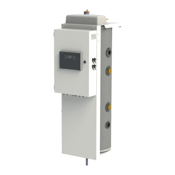
- Page 1 Z1 Pilot Hydraulic pilot for heat pumps Installation manual Z1 Pilot 78 liters - 10 hydraulic outlets Ref. 753041 Made in France Manual ref. : 1898978 Edition n° : 23.38...
-
Page 2: Table Of Contents
TABLE OF CONTENTS 1 - SAFETY ............4 4.3 - Electrical connections ..............14 4.3.1 - Power electrical connections ................14 4.3.2 - Prior recommandations before power electrical connections ....14 2 - PLEASE READ IMMEDIATELY ......6 4.3.3 - Connecting the hydraulic pilot electrical board ...........15 2.1 - Conservation of documents ............6 4.3.4 - Power connection of the HRC heat pump ............15... - Page 3 + 1 DHW tank + 1 heating circuit (radiator) ..48 A3.5 - CASE n°5 - 1 HRC heat pump + 2 DHW tanks ..........49 A6.1 - Z1 pilot with HRC 32kW /3 three-phase heat pump .......88 A3.6 - CASE n°6 - 1 HRC heat pump + 3 heating circuits (radiator) ....50...
-
Page 4: Safety
1 - SAFETY Danger resulting from improper qualifi cations Danger of death if the pressure relief valves are missing or defective • Any work carried out by an unqualifi ed person can result in damage to the installation or in A defective pressure relief valve may prove physical injury. - Page 5 (see § Connecting the pressure relief valve). Maintenance - Troubleshooting Maintenance and cleaning of the pilot must be carried out at least once a year by a qualifi ed professional. PILOT MANUAL...
-
Page 6: Please Read Immediately
Admissible storage and transport temperatures are from -20°C to +60°C. The Z1 Pilot must be stored in its packaging. It must be transported This technical installation manual forms part of the appliance which empty of water, horizontally, in its original packaging. -
Page 7: Introduction
• Ambient temperature thermostat radio non- chronoproportional -TH (on/off type). Wireless, programmable thermostat, transmitting through radio-frequency. Necessary when a wired connection between the Z1 Pilot and the ambient temperature thermostat is not possible (Ref. 770001) • Thermo-Net gateway Communication gateway for remote comfort control via an Internet box. -
Page 8: Operating Principles
4 - INSTALLATION • Heat pump hydraulic branch For models below 40kW with PWM circulator Ref. 754205 4.1 - Placement choice • 6kW Electrical back-up Ref. 754105 4.1.1 - Appropriate placement choice • V3V start sensor The Pilot must be placed in an area which is free from frost and adverse weather conditions. -
Page 9: Hydraulic Installation
Suffi cient fl ow must be ensured in the circuits connected to the Z1 pilot. In the case of an installation with thermostatic valves, this check must be carried out with all the valves open. The power actually required will determine the fl ow of heating water and, by the same token, the calculation of the distribution network. -
Page 10: Frost Protection
4.2.1.7 - Frost protection Central heating installations must be Frost protection is necessary if the pilot is switched off during the cleaned in order to eliminate debris (copper, winter months (ex: secondary residence, etc...). fi lings, soldering waste) related to the set-up of the installation or from chemical reactions between the If the pilot is connected to electricity, metals. -
Page 11: Installation Of The Dhw Circuit
4.2.1.10 - Installation of the DHW circuit mandatory It is to refer to the technical manual provided with each water tank. mandatory It is to install a safety group on the cold water inlet of each water tank. Do not place a stop valve between the safety group and the water tank. •... -
Page 12: Water Inlet Fi Lter For Each Heat Pump (Supplied)
4.2.1.13 - Water inlet fi lter for each heat pump (supplied) mandatory It is to install the 1’’ 1/4 fi lter with incorporated 500μm fi lter on the water inlet pipe of each heat pump : • Mind the fl ow direction of the fi lter. (arrow). •... -
Page 13: Connection Of The Circulators In The Source Circuits
4.2.2.2.2 - Connection of the circulators in 4.2.2.2.3 - Circulator speed adjustment the source circuits Le réglage de la vitesse des circulateurs - selon le modèle - est détaillé The flow rate in the sending circuits is provided by the AUTO dans la notice fournie avec les branches hydrauliques. -
Page 14: Underfl Oor Heating Connection
4.2.2.4 - Underfl oor heating connection 4.3 - Electrical connections 4.2.2.4.1 - Connecting one or more 4.3.1 - Power electrical connections underfl oor heating systems If the installation includes one or more underfl oor heating systems, the circuit(s) must be fi tted with the following components: The rules and regulations in the country of - AUTO hydraulic branch (Ref. -
Page 15: Connecting The Hydraulic Pilot Electrical Board
A dedicated switch/circuit breaker should be installed in the It is MANDATORY to read the installation electrical panel to supply the Z1 Pilot. It must allow total mains manual provided with each HRC heat disconnection (all-pole) to eliminate any danger during maintenance pump. -
Page 16: Cascade Of Heat Pumps
Plan for the appropriate length of cable between the pilot and the Ensure that the connecting cable heat pump. Do not hesitate to cut the cable to the appropriate is distanced from any source of length to AVOID LOOPS. electrical disturbance (ex: washing machine, neon lighting, power supply cable..) It is IMPERATIVE... -
Page 17: Connection Of Electrical Back-Up (Optional)
4.3.7 - Connection of electrical back-up (optional) The 6kW (3x2kW) electric back-up (Ref. 754105) complements the heat pump on the coldest days. Be sure to turn off the power when connecting the electrical back-up. Be sure to install the electrical back-up heater when the tank is empty of water. 1. - Page 18 7. Connect the link cable between the power board and the display board. (See diagram below) 8. Remove the pre-cut cover on the side of the housing and screw the thermal cut-out into the hole provided. Place the bulb in the pocket above the pilot and connect the thermal cut-out to the power board (see diagram below). Connect the wires to terminals A1 and A2 on the thermal overload protection.
- Page 19 For single-phase connection, the phase must be connected to terminal P3. Connect the phase distribution bridges supplied in the plastic bag to connectors X2 and X3 (see the four colored and numbered lugs in the diagram below). The phase must be connected to terminal P3 and not to terminals P1 or P2. For three-phase connection, the phases must be connected to terminals P1, P2 and P3.
-
Page 20: Addressing For Transmitter Circuit Management
The electrical back-up and the Z1 pilot must be supplied by two separate supply circuits. Electrical auxiliaries must be protected by a dedicated single-pole + neutral or double-pole circuit breaker, depending on the type of installation and its electrical protection requirements (single-phase connection) or four- pole (three-phase connection), independently of the Z1 pilot supply circuit. -
Page 21: Connection Of Control Circuits And Accessories
Z1 pilot. The OPT is compulsory to protect the underfl oor heating system in the event of overheating. 4.4.3 - Exterior sensor The manually reset 65°C OPT must be installed on the underfl oor... -
Page 22: Set-Up
5 - SET-UP 5.3 - Starting set-up This factory setting must be changed, if necessary, in the «Installer» Menu. Set-up must be done by a qualifi ed professional. 5.1 - Before set-up Ensure that: - All work carried out on the hydraulic circuits and the electrical circuits are in compliance with the regulations in effect (inspection by a qualifi ed professional) When the Pilot is turned on for the fi rst time, it will ask you to confi rm... -
Page 23: Step 4 : Purging The Installation
5.3.4 - Step 4 : Purging the installation The purging cycle activates the circulator pump at an alternating rhythm to allow AIR BLEED the displacement and purging of any air bubbles accumulated at high points of the installation using the Pilot’s automatic purger. -
Page 24: Settings And Functions
6 - SETTINGS AND FUNCTIONS 6.1 - Control panel 6.1.1 - Keypad Primary function Secondary function (short press) (long press) - menu access locking / unlocking of the - return / cancel keypad - switch on standby mode - setting the program scheduled temperatures comfort modes... -
Page 25: Menus
- OUTS.TMIN : Outside temperature on the coldest day (return to factory settings) press for 5s - MODE : Choice of Z1 pilot operation : HP only operation HP+B ACKUP : Operation with the heat pump and authorised back-up BACK up... -
Page 26: List Of Adjustable Parameters
6.4 - List of adjustable parameters Factory Parameter N° Description Unit Range of setting setting P202 11 to 25 Maximum exterior temperature (warmest day for heat curve) °C P203 -30 to 10 Minimum exterior temperature ( (coldest day for heat curve)) °C auto: changeover is done automatically based on the P204... - Page 27 Factory Parameter N° Description Unit Range of setting setting P226 Choice for pressure sensor do not change the setting P227 10 to 100 Speed of heat pump circulator pump P228 Post-circulation of the heat pump circulator pump Do not change the setting P230 Not concerned auto: automatic set temperature from the air sensor or...
- Page 28 Factory Parameter N° Description Unit Range of setting setting Underfl oor heating circuit - Complementary self- oui : correction enabled p259 adaptability: automatic correction of the temperature on a non : correction disabled 3h cycle of room temperature Underfl oor heating circuit (mixed circuit option) - Room P267 0,1 to 1 temperature hysteresis (requires a room sensor): room...
-
Page 29: Description Of Functionalities
6.5.1.2 - Lowering of the temperature 6.5 - Description of functionalities The set temperature of heating can be lowered at the same time as 6.5.1 - Functions related to heating the ambient temperature when in Eco or Frost protection modes to improve the heat pump’s performance. -
Page 30: Automatic Summer/Winter Changeover
6.5.2.2 - Automatic summer/winter changeover 6.5.4 - Functions related to the production of domestic hot water With the automatic summer/winter changeover function activated, the pilot decides when to enact the changeover from one season 6.5.4.1 - Domestic priority sharing to another, independently from the choice made by the user via Allows the operation of the heating circuit at the end of the domestic the on/off button. -
Page 31: Maintenance And Troubleshooting
7 - MAINTENANCE AND * If the USB stick is not recognized, disconnect and reconnect the electrical supply to the appliance and try again. If the USB stick is still not being recognized, try a diff erent USB stick. TROUBLESHOOTING In the user menu, the USB sub-menu allows you to set the frequency of monitoring of operating history (every minute, every 30 seconds..). -
Page 32: Water Sensors
7.1.3 - Water sensors Counter n° Description Unit Ohmic values for T_pilote (pilot outlet) and T_water (domestic water C-28 Activation of high pressure switch for compressor n°2 quantity sensor placed in the tank) sensors Activation of low pressure switch for refrigerant C-29 quantity fl uid... -
Page 33: Errors Indicated By The Pilot
7.1.7 - Errors indicated by the pilot Press to stop the sound signal (the error persists) Whatever the number of connected heat pumps, errors denomination is the same. If several heat pumps are connected, error alternately appears with the heat pump which is concerned. Display Error Possible causes... - Page 34 Press for 2 seconds to remove the errors manually (indicated by «press »). Display Error Possible causes Consequences Reset - The hydraulic connection between the heat pump rev. flow Flow rate is reversed and the pilot is reversed heat pump stopped* manual - The heat pump’s inlet and outlet sensors are reversed - The heat pump’s evaporator or the grills of the...
- Page 35 Display Error Possible causes Consequences Reset - The exterior sensor is badly positioned and is being ext. senso. Exterior sensor placement error infl uenced by heat or cold sources informative message manual diag - The exterior sensor or the air sensor is defective automatic after PRES Sure Lack of water pressure...
-
Page 36: Spare Parts
8 - SPARE PARTS PILOT MANUAL... - Page 37 Rep. Réf. Désignation B1239277 1’’1/2 valve B1593083 2 pces 1’’1/2 --> 1’’1/2 plumbing fi tting B1244897 UPMXL 25-125 PWM circulator pump B1239287 1’’1/2 check valve B1134481 1’’1/2 plumbing fi tting PWM hydraulic set (for HRC 25kW and B4994834 32kW) B1239216 1/2’’...
- Page 38 PILOT MANUAL...
-
Page 39: Warranty
9 - WARRANTY 9.2.2.2 - Handling Cases (not limited) for exclusion from warranty: • Any damage sustained by impacts or falls during handling after delivery from the factory. 9.1 - Warranty coverage • Deterioration in the condition of the appliance after handling where the instructions in the manual have not been followed. -
Page 40: Appendix
APPENDIX A1 - Technical specifi cations A1.1 - General characteristics A1.3 - Dimensions Electrical supply 230 V mono Power supply cable cross- 3G 2,5 mm² section Circuit braker 10 A Buff er tank 78 L Dimensions (W x H x D) 410 x 1512 x 536 Weight when empty 50 kg... -
Page 41: A2 - Hydraulic Connections Between The Pilot And The Heat Pumps
A2 - Hydraulic connections between the pilot and the heat pumps A2.1 - HRC 20kW heat pump Minimum Ø of piping to respect Steel Copper Multilayer If distance between HP and Pilot < 10m 1’’ 25/28 26/32 26/32 (the equivalent of 20m linear of loss of load) If distance between HP and Pilot >... -
Page 42: A3 - Wiring Diagrams
A2.4 - HRC 40kW heat pump Minimum Ø of piping to respect Steel Copper Multilayer If distance between HP and Pilot < 10m 1’’1/4 32/35 42/50 40,8/50 (the equivalent of 20m linear of loss of load) If distance between HP and Pilot > 10m and < 20m 1’’1/2 38/40 42/50... -
Page 43: A3.1 - Case N°1 - 1 Hrc
CPAC : Heat pump circulator S : Z1 valve VA : Shut-off valve DRD : Flow adjuster P : Z1 purger Z1 pilot VCB : Mud fl ush valve : Limit of supply Regulation 230V single-phase power supply Only with HRC <= 32kW... -
Page 44: A3.1.2 - Heating Circuit - Underfl Oor Heating
CPAC : Heat pump circulator S : Z1 valve VA : Shut-off valve DRD : Flow adjuster P : Z1 purger Z1 pilot VCB : Mud fl ush valve : Limit of supply Regulation 230V single-phase power supply Only with HRC <= 32kW... -
Page 45: A3.2 - Case N°2 - 1 Hrc
S : Z1 valve VA : Shut-off valve VEQ : balancing valve P : Z1 purger VCB : Mud fl ush valve : Limit of supply Z1 pilot 230V single-phase power supply Regulation Only with HRC <= 32kW 3G 2.5 power supply... -
Page 46: A3.3 - Case N°3 - 1 Hrc
S : Z1 valve VA : Shut-off valve DRD : Flow adjuster P : Z1 purger VCB : Mud fl ush valve : Limit of supply Z1 pilot Regulation 230V single-phase power supply Only with HRC <= 32kW PILOT MANUAL... -
Page 47: A3.3.2 - Heating Circuit - Underfl Oor Heating
CPAC : Heat pump circulator S : Z1 valve VA : Shut-off valve DRD : Flow adjuster P : Z1 purger VCB : Mud fl ush valve Z1 pilot : Limit of supply 230V single-phase power supply Regulation Only with HRC <= 32kW... -
Page 48: A3.4 - Case N°4 - 1 Hrc
CPAC : Heat pump circulator S : Z1 valve VA : Shut-off valve DRD : Flow adjuster P : Z1 purger Z1 pilot VCB : Mud fl ush valve : Limit of supply Regulation 230V single-phase power supply Only with HRC <= 32kW... -
Page 49: A3.5 - Case N°5 - 1 Hrc
S : Z1 valve VA : Shut-off valve VEQ : balancing valve P : Z1 purger VCB : Mud fl ush valve : Limit of supply Z1 pilot Regulation 230V single-phase power supply Only with HRC <= 32kW 3G 2.5 power supply... -
Page 50: A3.6 - Case N°6 - 1 Hrc
S : Z1 valve VA : Shut-off valve VEQ : balancing valve P : Z1 purger VCB : Mud fl ush valve : Limit of supply Z1 pilot 230V single-phase power supply Regulation Only with HRC <= 32kW 3G 2.5 power supply... -
Page 51: Heat Pump + 1 Dhw Tank + 2 Heating Circuits (Radiator)
CPAC : Heat pump circulator S : Z1 valve VA : Shut-off valve DRD : Flow adjuster P : Z1 purger Z1 pilot VCB : Mud fl ush valve : Limit of supply Regulation 230V single-phase power supply Only with HRC <= 32kW... -
Page 52: Heat Pump + 2 Dhw Tanks + 1 Heating Circuit (Radiator)
S : Z1 valve VA : Shut-off valve VEQ : balancing valve P : Z1 purger VCB : Mud fl ush valve : Limit of supply Z1 pilot Regulation 230V single-phase power supply Only with HRC <= 32kW 3G 2.5 power supply... -
Page 53: Heat Pump + 3 Dhw Tanks
S : Z1 valve VA : Shut-off valve VEQ : balancing valve P : Z1 purger VCB : Mud fl ush valve : Limit of supply Z1 pilot Regulation 230V single-phase power supply Only with HRC <= 32kW 3G 2.5 power supply... -
Page 54: A3.10.1 - Heating Circuit - Radiator
CPAC : Heat pump circulator S : Z1 valve VA : Shut-off valve DRD : Flow adjuster P : Z1 purger Z1 pilot VCB : Mud fl ush valve : Limit of supply Regulation 230V single-phase power supply Only with HRC <= 32kW... -
Page 55: A3.10.2 - Heating Circuit - Underfl Oor Heating
CPAC : Heat pump circulator S : Z1 valve VA : Shut-off valve DRD : Flow adjuster P : Z1 purger Z1 pilot VCB : Mud fl ush valve : Limit of supply 230V single-phase power supply Regulation Only with HRC <= 32kW... -
Page 56: Heat Pumps + 1 Dhw Tank
TA : Ambient thermostat SA : Ambient sensor Sext : Outdoor sensor PPac : Heat pump purger Z1 pilot Filter : Sieve fi lter LTP : OPT : Overheat protection thermostat VE : Expansion vessel SECS : DHW sensor / DHW aquastat : DHW aquastat... -
Page 57: A3.12 - Case N°12 - 2 Hrc
CPAC : Heat pump circulator S : Z1 valve VA : Shut-off valve DRD : Flow adjuster P : Z1 purger Z1 pilot VCB : Mud fl ush valve : Limit of supply Regulation 230V single-phase power supply Only with HRC <= 32kW... -
Page 58: A3.12.2 - Heating Circuit - Underfl Oor Heating
CPAC : Heat pump circulator S : Z1 valve VA : Shut-off valve DRD : Flow adjuster P : Z1 purger Z1 pilot VCB : Mud fl ush valve : Limit of supply Regulation 230V single-phase power supply Only with HRC <= 32kW... -
Page 59: A3.13 - Case N°13 - 2 Hrc
Hose Hose TA : Ambient thermostat SA : Ambient sensor Sext : Outdoor sensor Z1 pilot PPac : Heat pump purger Filter : Sieve fi lter LTP : OPT : Overheat protection thermostat VE : Expansion vessel SECS : DHW sensor / DHW aquastat : DHW aquastat... -
Page 60: A3.14 - Case N°14 - 2 Hrc
Hose Hose TA : Ambient thermostat SA : Ambient sensor Sext : Outdoor sensor Z1 pilot PPac : Heat pump purger Filter : Sieve fi lter LTP : OPT : Overheat protection thermostat VE : Expansion vessel SECS : DHW sensor / DHW aquastat : DHW aquastat... -
Page 61: A3.15 - Case N°15 - 2 Hrc
Hose Hose TA : Ambient thermostat SA : Ambient sensor Sext : Outdoor sensor Z1 pilot PPac : Heat pump purger Filter : Sieve fi lter LTP : OPT : Overheat protection thermostat VE : Expansion vessel SECS : DHW sensor / DHW aquastat : DHW aquastat... -
Page 62: A3.15.2 - Heating Circuit - Underfl Oor Heating
Hose Hose TA : Ambient thermostat SA : Ambient sensor Sext : Outdoor sensor Z1 pilot PPac : Heat pump purger Filter : Sieve fi lter LTP : OPT : Overheat protection thermostat VE : Expansion vessel SECS : DHW sensor / DHW aquastat : DHW aquastat... -
Page 63: A3.16 - Case N°16 - 2 Hrc
TA : Ambient thermostat SA : Ambient sensor Sext : Outdoor sensor PPac : Heat pump purger Z1 pilot Filter : Sieve fi lter LTP : OPT : Overheat protection thermostat VE : Expansion vessel SECS : DHW sensor / DHW aquastat : DHW aquastat... -
Page 64: A3.17 - Case N°17 - 2 Hrc
TA : Ambient thermostat SA : Ambient sensor Sext : Outdoor sensor PPac : Heat pump purger Z1 pilot Filter : Sieve fi lter LTP : OPT : Overheat protection thermostat VE : Expansion vessel SECS : DHW sensor / DHW aquastat : DHW aquastat... -
Page 65: A3.18 - Case N°18 - 2 Hrc
Hose Hose TA : Ambient thermostat SA : Ambient sensor Sext : Outdoor sensor Z1 pilot PPac : Heat pump purger Filter : Sieve fi lter LTP : OPT : Overheat protection thermostat VE : Expansion vessel SECS : DHW sensor / DHW aquastat : DHW aquastat... -
Page 66: A3.19 - Case N°19 - 3 Hrc
CPAC : Heat pump circulator S : Z1 valve VA : Shut-off valve DRD : Flow adjuster P : Z1 purger VCB : Mud fl ush valve : Limit of supply Z1 pilot Regulation 230V single-phase power supply PILOT MANUAL... -
Page 67: A3.19.2 - Heating Circuit - Underfl Oor Heating
CPAC : Heat pump circulator S : Z1 valve VA : Shut-off valve DRD : Flow adjuster P : Z1 purger VCB : Mud fl ush valve : Limit of supply Z1 pilot 230V single-phase Regulation power supply PILOT MANUAL... -
Page 68: A3.20 - Case N°20 - 3 Hrc
SECS : DHW sensor / DHW aquastat : DHW aquastat SPac : Heat pump valve CPAC : Heat pump circulator S : Z1 valve Z1 pilot VA : Shut-off valve VEQ : balancing valve P : Z1 purger VCB : Mud fl ush valve... -
Page 69: A3.21 - Case N°21 - 3 Hrc
CPAC : Heat pump circulator S : Z1 valve VA : Shut-off valve DRD : Flow adjuster P : Z1 purger VCB : Mud fl ush valve : Limit of supply Z1 pilot Regulation 230V single-phase power supply PILOT MANUAL... -
Page 70: A3.7 - Case N°7 - 1 Hrc
CPAC : Heat pump circulator S : Z1 valve VA : Shut-off valve DRD : Flow adjuster P : Z1 purger VCB : Mud fl ush valve : Limit of supply Z1 pilot 230V single-phase Regulation power supply PILOT MANUAL... -
Page 71: A3.22 - Case N°22 - 3 Hrc
SECS : DHW sensor / DHW aquastat : DHW aquastat SPac : Heat pump valve CPAC : Heat pump circulator S : Z1 valve VA : Shut-off valve Z1 pilot VEQ : balancing valve P : Z1 purger VCB : Mud fl ush valve : Limit of supply... -
Page 72: A3.23 - Case N°23 - 3 Hrc
SECS : DHW sensor / DHW aquastat : DHW aquastat SPac : Heat pump valve CPAC : Heat pump circulator S : Z1 valve Z1 pilot VA : Shut-off valve VEQ : balancing valve P : Z1 purger VCB : Mud fl ush valve... -
Page 73: A3.24 - Case N°24 - 3 Hrc
CPAC : Heat pump circulator S : Z1 valve VA : Shut-off valve DRD : Flow adjuster P : Z1 purger VCB : Mud fl ush valve : Limit of supply Z1 pilot Regulation 230V single-phase power supply PILOT MANUAL... -
Page 74: A3.24.2 - Heating Circuit - Underfl Oor Heating
CPAC : Heat pump circulator S : Z1 valve VA : Shut-off valve DRD : Flow adjuster P : Z1 purger VCB : Mud fl ush valve : Limit of supply Z1 pilot Regulation 230V single-phase power supply PILOT MANUAL... -
Page 75: Heat Pumps + 1 Dhw Tank + 2 Heating Circuits
VE : Expansion vessel SECS : DHW sensor / DHW aquastat : DHW aquastat SPac : Heat pump valve CPAC : Heat pump circulator Z1 pilot S : Z1 valve VA : Shut-off valve VEQ : balancing valve P : Z1 purger... -
Page 76: Heat Pumps + 2 Dhw Tank + 1 Heating Circuit
LTP : OPT : Overheat protection thermostat VE : Expansion vessel SECS : DHW sensor / DHW aquastat : DHW aquastat SPac : Heat pump valve Z1 pilot CPAC : Heat pump circulator S : Z1 valve VA : Shut-off valve... -
Page 77: Heat Pumps + 3 Dhw Tanks
LTP : OPT : Overheat protection thermostat VE : Expansion vessel SECS : DHW sensor / DHW aquastat : DHW aquastat SPac : Heat pump valve Z1 pilot CPAC : Heat pump circulator S : Z1 valve VA : Shut-off valve... -
Page 78: A3.28 - Direct And Mixed Circuit Confi Gurations
S : Z1 valve VA : Shut-off valve VEQ : balancing valve P : Z1 purger VCB : Mud fl ush valve : Limit of supply Z1 pilot Regulation 230V single-phase power supply Only with HRC <=32kW 3G 2.5 power supply tab n°1 lowered... -
Page 79: Underfl Oor Heating Circuit
S : Z1 valve VA : Shut-off valve VEQ : balancing valve P : Z1 purger VCB : Mud fl ush valve : Limit of supply Z1 pilot Regulation 230V single-phase power supply Only with HRC <=32kW 3G 2.5 power supply tab n°1 lowered... -
Page 80: Underfl Oor Heating Circuit
TA : Ambient thermostat SA : Ambient sensor Sext : Outdoor sensor PPac : Heat pump purger Z1 pilot Filter : Sieve fi lter LTP : OPT : Overheat protection thermostat VE : Expansion vessel SECS : DHW sensor / DHW aquastat : DHW aquastat... -
Page 81: Underfl Oor Heating Circuit
TA : Ambient thermostat SA : Ambient sensor Sext : Outdoor sensor PPac : Heat pump purger Z1 pilot Filter : Sieve fi lter LTP : OPT : Overheat protection thermostat VE : Expansion vessel SECS : DHW sensor / DHW aquastat : DHW aquastat... -
Page 82: Underfl Oor Heating Circuit
S : Z1 valve VA : Shut-off valve DRD : Flow adjuster P : Z1 purger VCB : Mud fl ush valve : Limit of supply Z1 pilot Regulation 230V single-phase power supply 3G 2.5 power supply tab n°1 lowered Pressure sensor... -
Page 83: Underfl Oor Heating Circuit
S : Z1 valve VA : Shut-off valve VEQ : balancing valve P : Z1 purger VCB : Mud fl ush valve : Limit of supply Z1 pilot Regulation 230V single-phase power supply 3G 2.5 power supply tab n°1 lowered Pressure sensor... -
Page 84: A4 - Wiring Diagram
A4 - Wiring diagram A4.1 - Wiring diagram without electrical back-up : Ambient thermostat : Ambient temperature sensor AQS : Aquastat ModBUS cable connection : Brown : White GND : Black * Dry contact to be connected to room control input of boiler back-up. ** Do not disconnect the shunt mounted on the board. -
Page 85: A4.2 - Wiring Diagram With Electrical Back-Up
A4.2 - Wiring diagram with electrical back-up Dry contact* Boiler back-up Outdoor sensor Peak / off -peak contact Pilot temperature sensor Pressure sensor Power supply circuit 4 heating / DHW Power supply circuit 3 heating / DHW HP3 circulator PWM HP2 circulator PWM HP1 circulator PWM Power supply circuit 2... -
Page 86: Settings And Functions
A.5 -Settings and functions A.5.1 - Control panel A.5.1.1 - Keypad Primary function Secondary function (short press) (long press) - menu access locking / unlocking of the - return / cancel keypad - switch on standby mode - setting the program scheduled temperatures comfort modes... -
Page 87: Menus
- OUTS.TMIN : Outside temperature on the coldest day (return to factory settings) press for 5s - MODE : Choice of Z1 pilot operation : HP only operation HP+B ACKUP : Operation with the heat pump and authorised back-up BACK up... -
Page 88: A6 - Product Technical Information Sheet
A6 - Product technical information sheet A6.1 - Z1 pilot with HRC 32kW /3 three-phase heat pump PILOT MANUAL... -
Page 89: 40Kw /3 Three-Phase Heat Pump
A6.2 - Z1 pîlot with HRC 40kW /3 three-phase heat pump PILOT MANUAL... -
Page 90: 40Kw Three-Phase Cascade Heat Pump
A6.3 - Z1 pilot with HRC 40kW three-phase Cascade heat pump PILOT MANUAL... -
Page 91: 50Kw Thre-Phase Cascade Heat Pump
A6.4 - Z1 pilot with HRC 50kW thre-phase Cascade heat pump PILOT MANUAL... -
Page 92: 64Kw Three-Phase Cascade Heat Pump
A6.5 - Z1 pilot with HRC 64kW three-phase Cascade heat pump PILOT MANUAL... -
Page 93: 75Kw Three-Phase Cascade Heat Pump
A6.6 - Z1 pilot with HRC 75kW three-phase Cascade heat pump PILOT MANUAL... -
Page 94: 80Kw Three-Phase Cascade Heat Pump
A6.7 - Z1 pilot with HRC 80kW three-phase Cascade heat pump PILOT MANUAL... -
Page 95: 96Kw Three-Phase Cascade Heat Pump
A6.8 - Z1 pilot with HRC 96kW three-phase Cascade heat pump PILOT MANUAL... - Page 96 Rue de la République CS 40029 80210 Feuquières-en-Vimeu Spare parts department Tel. : 03 22 61 21 21 Fax : 03 22 61 33 35 E-mail : pieces@intuis.fr Technical assistance department* E-mail : sav@intuis.fr *Technical assistance is reserved for professionals...
Need help?
Do you have a question about the Z1 Pilot and is the answer not in the manual?
Questions and answers