EWM TGM 40230 Handy Operating Instructions Manual
Electrode grinding machine
Hide thumbs
Also See for TGM 40230 Handy:
- Operating instructions manual (23 pages) ,
- Operating instructions manual (27 pages)

Related Manuals for EWM TGM 40230 Handy

Summary of Contents for EWM TGM 40230 Handy
- Page 1 Operating instructions Electrode grinding machine TGM 40230 Handy 099-003412-EW501 Observe additional system documents! 09.08.2023...
- Page 2 +49 2680 181-0. A list of authorised sales partners can be found at www.ewm-group.com/en/specialist-dealers. Liability relating to the operation of this equipment is restricted solely to the function of the equipment. No other form of liability, regardless of type, shall be accepted.
-
Page 3: Table Of Contents
Declaration of Conformity ..................11 3.2.3 Service documents (spare parts) ................. 11 4 Machine description – quick overview ..................12 TGM 40230 Handy ....................... 12 5 Design and function ........................13 Transport and installation ....................13 5.1.1 Ambient conditions ....................14 5.1.2... -
Page 4: For Your Safety
For your safety Notes on using these operating instructions For your safety Notes on using these operating instructions DANGER Working or operating procedures which must be closely observed to prevent imminent serious and even fatal injuries. • Safety notes include the "DANGER" keyword in the heading with a general warning symbol. •... -
Page 5: Explanation Of Icons
For your safety Explanation of icons Explanation of icons Symbol Description Symbol Description Indicates technical aspects which the Activate and release / Tap / Tip user must observe. Switch off machine Release Switch on machine Press and hold Incorrect / Invalid Switch Correct / Valid Turn... -
Page 6: Safety Instructions
For your safety Safety instructions Safety instructions WARNING Risk of accidents due to non-compliance with the safety instructions! Non-compliance with the safety instructions can be fatal! • Carefully read the safety instructions in this manual! • Observe the accident prevention regulations and any regional regulations! •... - Page 7 For your safety Safety instructions WARNING Risk of injury due to improper clothing! During arc welding, radiation, heat and voltage are sources of risk that cannot be avoided. The user has to be equipped with the complete personal protective equipment at all times.
- Page 8 For your safety Safety instructions CAUTION Smoke and gases! Smoke and gases may lead to shortness of breath and poisoning! The ultraviolet radia- tion of the arc may also convert solvent vapours (chlorinated hydrocarbon) into poiso- nous phosgene. • Ensure sufficient fresh air! •...
-
Page 9: Transport And Installation
For your safety Transport and installation CAUTION Obligations of the operator! The respective national directives and laws must be complied with when operating the machine! • Implementation of national legislation relating to framework directive 89/391/EEC on the int- roduction of measures to encourage improvements in the safety and health of workers at work and associated individual guidelines. - Page 10 For your safety Transport and installation CAUTION Risk of accidents due to supply lines! During transport, attached supply lines (mains leads, control cables, etc.) can cause risks, e.g. by causing connected machines to tip over and injure persons! • Disconnect all supply lines before transport! Risk of tipping! There is a risk of the machine tipping over and injuring persons or being damaged itself during movement and set up.
-
Page 11: Intended Use
3.2.1 Warranty For more information refer to the "Warranty registration" brochure supplied and our information regarding warranty, maintenance and testing at www.ewm-group.com! 3.2.2 Declaration of Conformity This product corresponds in its design and construction to the EU directives listed in the decla- ration. -
Page 12: Machine Description - Quick Overview
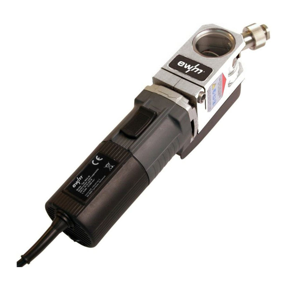
Machine description – quick overview TGM 40230 Handy Machine description – quick overview TGM 40230 Handy Figure 4-1 Item Symbol Description Infeed channel Guide element for setting the grinding tracks Grinding attachment Depth gauge Grinding attachment clamping bolt On/off switch... -
Page 13: Design And Function
Design and function Transport and installation Design and function WARNING Harmful electrode material! Electrodes may contain harmful substances! • Observe the instructions by the electrode manufacturer! CAUTION Open infeed channel! If the infeed channel is left open, chips and dirt particles can be expelled from the chan- nel when the grinding disk is running and might get into the eyes or be breathed in! •... -
Page 14: Ambient Conditions
Design and function Transport and installation 5.1.1 Ambient conditions Equipment damage due to contamination! Unusually high amounts of dust, acids, corrosive gases or substances can damage the machine (observe maintenance intervals > see 6 chapter). • Avoid large amounts of smoke, steam, oily fumes, grinding dust and corrosive ambient air! Insufficient ventilation results in a reduction in performance and equipment damage. -
Page 15: Mains Connection
Design and function Presets 5.1.2 Mains connection DANGER Hazards caused by improper mains connection! An improper mains connection can cause injuries or damage property! • The connection (mains plug or cable), the repair or voltage adjustment of the device must be carried out by a qualified electrician in accordance with the respective local laws or nati- onal regulations! •... -
Page 16: Preparing Electrodes For The Grinding Process
Design and function Presets Figure 5-2 Item Symbol Description Clamping bolt Guide element for setting the grinding tracks "S" mark Grinding disk Grinding track • Unfasten the clamping bolt. • Lift up the guide element. • Rotate the guide element by 90°. •... -
Page 17: Setting The Grinding Angle Of The Tungsten Electrode
Design and function Presets Item Symbol Description Electrode holder Area of application: unalloyed and low-alloy materials • Select the collet chuck according to the electrode diameter. • Insert the electrode into the collet chuck. • Screw the collet chuck into the electrode holder. Collet chucks supplied! Collet chucks for electrode diameters of 1.6, 2.4 and 3.2 mm are included as standard. -
Page 18: Setting The Speed
Design and function Presets 5.2.4 Setting the speed Using a speed that matches the electrode diameter is very important to achieve precise and clean grin- ding of the electrode. Figure 5-5 Item Symbol Description Mains connection cable > see 5.1.2 chapter Motor casing Speed controller •... -
Page 19: Inserting The Electrode
Design and function Inserting the electrode Inserting the electrode Before every grinding operation: Set the electrode grinding using the grinding attachment clamping bolt depth gauge. Figure 5-6 Item Symbol Description Infeed channel Grinding attachment Depth gauge setting bolt Depth gauge Electrode holder Grinding disk Electrode... -
Page 20: Changing The Filter
Design and function Changing the filter Figure 5-7 Item Symbol Description Electrode holder Stop piece Infeed channel Grinding attachment • Check whether the on/off switch is in the “0” position. • Connect the machine to the power supply. • Use the sight glass to check that the electrode is not resting on the grinding wheel. •... - Page 21 Design and function Changing the filter Disposal! Use the waste disposal bags supplied for single use filters to dispose of used filter cartridges! Observe local regulations for the disposal of filter cartridges! The filter needs to be changed when there are considerable deposits of grinding particles on the inspec- tion glass.
-
Page 22: Replacing The Grinding Disk
Design and function Replacing the grinding disk Replacing the grinding disk Figure 5-9 Item Symbol Description Stop bolt Open-ended spanner, SW 17 Grinding attachment Connecting link Allen key, SW 8 Grinding attachment clamping bolt Grinding disk Motor casing Open-ended spanner, SW 14 Open-ended spanner, SW 13 099-003412-EW501 09.08.2023... - Page 23 Design and function Replacing the grinding disk • Remove the electrode holder. • Remove the stop bolt using the open-ended spanner (SW 17). • Remove the connecting link forwards with the inspection glass. • Unfasten the grinding attachment clamping bolt using the bent-nosed Allan key (SW 8). •...
-
Page 24: Maintenance, Care And Disposal
Maintenance, care and disposal Cleaning Maintenance, care and disposal Cleaning WARNING Mains voltage! Before carrying out any cleaning or testing measures, ensure that all mains connections and supply lines of the machine are disconnected. • Disconnect all mains connections and supply lines. CAUTION Health hazard from grinding dust! When cleaning the grinding machine, residues of grinding dust may get into the eyes or... -
Page 25: Disposing Of Equipment
Information on returning used equipment or collections can be obtained from the respective municipal administration office. Devices can also be returned to EWM sales partners across Europe. Further information on the topic of the disposal of electrical and electronic equipment can be found on our website at: https://www.ewm-group.com/de/nachhaltigkeit.html. -
Page 26: Technical Data
Technical data TGM 40230 Handy Technical data TGM 40230 Handy Power 850 W Mains connection (EN 50144) 230 V / 50 Hz Speed 8000 – 22000 rpm Electrode diameter 0.8 - 4.0 mm Grinding angle 15 - 180° Maximum electrode length... -
Page 27: Replaceable Parts
Replaceable parts TGM 40230 Handy Type Designation Item no. COL Porta/Handy Ø 0.8 mm Collet chuck for EWM tungsten electrode grinders 098-003696-00000 COL Porta/Handy Ø 1.0 mm Collet chuck for EWM tungsten electrode grinders 098-003697-00000 COL Porta/Handy Ø 1.2 mm... -
Page 28: Appendix
Appendix Searching for a dealer Appendix Searching for a dealer Sales & service partners www.ewm-group.com/en/specialist-dealers "More than 400 EWM sales partners worldwide" 099-003412-EW501 09.08.2023...
Need help?
Do you have a question about the TGM 40230 Handy and is the answer not in the manual?
Questions and answers