Table of Contents
Advertisement
Quick Links
AL37204-EVB-A2
Evaluation Board
User Manual
Version 1.0
INFORMATION FURNISHED BY AVERLOGIC IS BELIEVED TO BE ACCURATE AND
RELIABLE. HOWEVER, NO RESPONSIBILITY IS ASSUMED BY AVERLOGIC FOR ITS USE,
OR FOR ANY INFRINGEMENTS OF PATENTS, OR OTHER RIGHTS OF THIRD PARTIES
THAT MAY RESULT FROM ITS USE. NO LICENSE IS GRANTED BY IMPLICATION OR
OTHERWISE UNDER ANY PATENT OR PATENT RIGHTS OF AVERLOGIC.
©2008-2009 Copyright by AverLogic Technologies, Corp.
AL37204-EVB-A1-User Manual-1.0-20090821
Advertisement
Table of Contents

Related Manuals for Averlogic AL37204-EVB-A2


Summary of Contents for Averlogic AL37204-EVB-A2
- Page 1 Version 1.0 INFORMATION FURNISHED BY AVERLOGIC IS BELIEVED TO BE ACCURATE AND RELIABLE. HOWEVER, NO RESPONSIBILITY IS ASSUMED BY AVERLOGIC FOR ITS USE, OR FOR ANY INFRINGEMENTS OF PATENTS, OR OTHER RIGHTS OF THIRD PARTIES THAT MAY RESULT FROM ITS USE. NO LICENSE IS GRANTED BY IMPLICATION OR OTHERWISE UNDER ANY PATENT OR PATENT RIGHTS OF AVERLOGIC.
- Page 2 AVERLOGIC TECHNOLOGIES RESERVES THE RIGHT TO MAKE CHANGES WITHOUT FURTHER NOTICE TO ANY PRODUCTS HEREIN TO IMPROVE RELIABILITY, FUNCTION OR DESIGN. AVERLOGIC DOES NOT ASSUME ANY LIABILITY ARISING OUT OF THE APPLICATION OR USE OF ANY PRODUCT OR CIRCUIT DESCRIBED HERIN; NEITHER DOES IT CONVEY ANY LICENSE UNDER ITS PATENT RIGHTS, NOR THE RIGHTS OF OTHERS.
-
Page 3: Table Of Contents
4.5 Camera Setup..........................11 4.6 Motion Setup ..........................11 4.7 Event Setup............................. 12 4.8 Event Report........................... 12 5 Display Modes....................13 6 Miscellaneous ....................14 6.1 Reset Button ........................... 14 6.2 Debug Mode ........................... 14 ©2008-2009 Copyright by AverLogic Technologies, Corp. AL37204-EVB-A1-User Manual-1.0-20090821... -
Page 4: Introduction
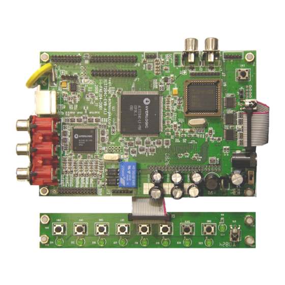
1.1 Product Description The AL37204 Video Processor EVB is an evaluation product that demonstrates a total solution for video surveillance applications using Averlogic IC chips. This EVB product receives video streams from up to 4 cameras to be processed and shown on a monitor in a variety of convenient display formats. -
Page 5: Block Diagram
Supports manual video standard selection to match various analog video standard inputs. High quality adaptive comb-filter for Y/C separation. Supports multi-window display modes (1/2/3/4/9/13/16). Three embedded TV Encoders with DACS, supports NTSC and PAL standard outputs. ©2008-2009 Copyright by AverLogic Technologies, Corp. - Page 6 Internal OSD overlay with programmable bitmap type font for OSD display Note: Please be aware that this is an Evaluation product only and not all functional capabilities of Averlogic components are fully demonstrated by this product. Please refer to the Averlogic website (www.averlogic.com) or contact your Averlogic representative (see last page of this document) for more information.
-
Page 7: Quick Setup
If it is not displaying the video, your connections may not be secure or your camera may be setup with the wrong standard (PAL or NTSC), for which you will need to review the configuration section below. ©2008-2009 Copyright by AverLogic Technologies, Corp. -
Page 8: Hardware Section
Connector for Keypad Panel IR Receiver Receives IR signal from Remote controller Note: There are other jumpers and connectors on this EVB board that are not described and are either disabled or not meant for use. ©2008-2009 Copyright by AverLogic Technologies, Corp. -
Page 9: Rear Panel Connectors
CVBS Video signal input port 4 S-Video IN S-Video signal input port (reserved) Note: There are other jumpers and connectors on this EVB board that are not described and are either disabled or not meant for use. ©2008-2009 Copyright by AverLogic Technologies, Corp. -
Page 10: Keypad Panel
Keypad panel. The labeled remote control buttons, located on the diagram to the right, correspond to the buttons shown above and are the only functional buttons used with this board. The other buttons are disabled and non-functional. ©2008-2009 Copyright by AverLogic Technologies, Corp. - Page 11 Also can be used to increment a value SW11 Up Arrow / CH-1 setting. Is also used to display CH-1 in single panel display. See the “System Menu” section for a complete description of all functions. ©2008-2009 Copyright by AverLogic Technologies, Corp.
-
Page 12: System Menu
2> TIME : HH-MM-SS 12:13:35 3> SYSTEM FORMAT:PAL Use your up/down, left/right arrow keys to navigate the 4> KEY LOCK:OFF 5> FACTORY RESET screen and the “enter” key (sw7) to accept the configuration. ©2008-2009 Copyright by AverLogic Technologies, Corp. -
Page 13: Display Setup
(in seconds) that any particular display mode screen will pause on the screen once displayed. AUTO SEQUENCE SET Unit:sec ---------------------------------- CAMERA1:1 CAMERA2:1 CAMERA1:1 CAMERA2:1 MULTI-2:1 MULTI-3:1 MULTI-4:1 MULTI-6:1 MULTI-9:1 PIP-2:1 ©2008-2009 Copyright by AverLogic Technologies, Corp. -
Page 14: Camera Setup
OFF ON OFF OFF SENSOR 00A 00A 00A 00A small black squares. As you adjust the “sensitivity” of a camera’s motion detection, the number of squares will increase or decrease inversely with the sensitivity setting. ©2008-2009 Copyright by AverLogic Technologies, Corp. -
Page 15: Event Setup
You can delete all of the alerts in the file by moving to the “DEL ALL” option at the bottom-right corner of this screen and pressing “enter” (sw7). EVENT REPORT NO YY-MM-DD HH:MM:SS CH ------------------------------------------- ------------------------------------------ ©2008-2009 Copyright by AverLogic Technologies, Corp. -
Page 16: Display Modes
Since this product is only an evaluation board with support for 4 cameras, 6-channel and 9-channel displays show duplicated channels for demonstration purposes. 6 CHANNEL 9 CHANNEL 3 CHANNEL PIP 2 CHANNEL POP ©2008-2009 Copyright by AverLogic Technologies, Corp. -
Page 17: Miscellaneous
6.2 Debug Mode Pressing the “SW6/Freeze” Key for 3 seconds will take you into debug mode. Averlogic Debugging Tools can help you debug the EVB. You can find details with the Averlogic Debugging Tools. ©2008-2009 Copyright by AverLogic Technologies, Corp. - Page 18 CONTACT INFORMATION AverLogic Technologies, Corp. URL: http://www.averlogic.com ©2008-2009 Copyright by AverLogic Technologies, Corp.
Need help?
Do you have a question about the AL37204-EVB-A2 and is the answer not in the manual?
Questions and answers