Table of Contents
Advertisement
Quick Links
AL37219C-EVB-A2-User Manual-1.1-20090327
AL37219C-EVB-A2
Evaluation Board
User Manual
Version 1.1
INFORMATION FURNISHED BY AVERLOGIC IS BELIEVED TO BE ACCURATE AND
RELIABLE. HOWEVER, NO RESPONSIBILITY IS ASSUMED BY AVERLOGIC FOR ITS USE,
OR FOR ANY INFRINGEMENTS OF PATENTS, OR OTHER RIGHTS OF THIRD PARTIES
THAT MAY RESULT FROM ITS USE. NO LICENSE IS GRANTED BY IMPLICATION OR
OTHERWISE UNDER ANY PATENT OR PATENT RIGHTS OF AVERLOGIC.
DOC Number:1-M-PAE319-0201
©2008-2009 Copyright by AverLogic Technologies, Corp.
Advertisement
Table of Contents

Related Manuals for Averlogic AL37219C-EVB-A2


Summary of Contents for Averlogic AL37219C-EVB-A2
- Page 1 Version 1.1 INFORMATION FURNISHED BY AVERLOGIC IS BELIEVED TO BE ACCURATE AND RELIABLE. HOWEVER, NO RESPONSIBILITY IS ASSUMED BY AVERLOGIC FOR ITS USE, OR FOR ANY INFRINGEMENTS OF PATENTS, OR OTHER RIGHTS OF THIRD PARTIES THAT MAY RESULT FROM ITS USE. NO LICENSE IS GRANTED BY IMPLICATION OR OTHERWISE UNDER ANY PATENT OR PATENT RIGHTS OF AVERLOGIC.
- Page 2 AVERLOGIC TECHNOLOGIES RESERVES THE RIGHT TO MAKE CHANGES WITHOUT FURTHER NOTICE TO ANY PRODUCTS HEREIN TO IMPROVE RELIABILITY, FUNCTION OR DESIGN. AVERLOGIC DOES NOT ASSUME ANY LIABILITY ARISING OUT OF THE APPLICATION OR USE OF ANY PRODUCT OR CIRCUIT DESCRIBED HEREIN; NEITHER DOES IT CONVEY ANY LICENSE UNDER ITS PATENT RIGHTS, NOR THE RIGHTS OF OTHERS.
-
Page 3: Table Of Contents
4.5 PIP Submenu ........................12 4.6 POP Submenu ......................... 13 4.7 Auto Sequence Submenu ....................14 4.8 Time Submenu ......................... 14 4.9 Alarm Submenu........................ 15 5 Remote Control ....................16 5.1 Remote Control Button Description.................. 16 ©2008-2009 Copyright by AverLogic Technologies, Corp. -
Page 4: Introduction
1.1 Product Description The AL37219 Video Processor EVB is an evaluation product that demonstrates a total solution for video surveillance applications using AverLogic IC chips. This EVB product can receive video streams from up to 9 cameras and can simultaneously display the video on a monitor in a variety of convenient display formats. -
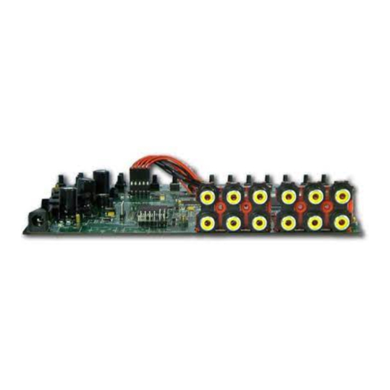
Page 5: Package Contents
AL37219 Mainboard with DC Adaptor 10 RCA cables (CVBS) Power Cord Remote Control Unit User Manual (not shown) 1.3 Block Diagram 1.4 Specifications Video Standard Support: NTSC and PAL Video Input Standard: CVBS Video Output Standard: CVBS ©2008-2009 Copyright by AverLogic Technologies, Corp. -
Page 6: Evb Features
Internal OSD overlay with programmable bitmap type fonts for OSD display Note: Please note that this is an evaluation product only and not all functional capabilities of AverLogic components are fully demonstrated by this product. Please refer to the AverLogic website (www.averlogic.com) or contact your AverLogic representative (see last page of this document) for more information. -
Page 7: Quick Setup
The AL37219-EVB-A2 product installation is fast and easy. In addition to the product packaging contents, you will need to provide a monitor that uses CVBS connections and at least one camera that is also equipped with a CVBS output connector. The setup diagram is shown below: ©2008-2009 Copyright by AverLogic Technologies, Corp. -
Page 8: Attach Camera (Cvbs Rca Connector)
2.4 Turn on the board power Toggle the power switch, which is located on the main board near the power adapter connector. A yellow-green LED next to the power switch will illuminate. ©2008-2009 Copyright by AverLogic Technologies, Corp. -
Page 9: If No Video Appears
Make sure that the camera is in working order and is delivering video. Make sure that the video standard (NTSC or PAL) used between camera and board is the same (to check board video standard, refer to the Systems Menu section – Systems Submenu). ©2008-2009 Copyright by AverLogic Technologies, Corp. -
Page 10: Hardware Section
Power Switch Mainboard Power Adapter Connector Power-On LED Indicator Rear Panel Rear Panel Note: The jumpers and connectors on this EVB board that are not described are either disabled or not meant for use. ©2008-2009 Copyright by AverLogic Technologies, Corp. -
Page 11: Rear Panel I/O Port Descriptions
This connector is an output connector for a monitor with a CVBS line 3.3 Reset Button In the event the EVB has entered an unstable state, you can press the reset button (marked SW2 on Mainboard) to reset the EVB. 3.4 Keypad Panel ©2008-2009 Copyright by AverLogic Technologies, Corp. - Page 12 These 9 keys are associated with the 9 cameras that can be attached to this CAM1-CAM9 board. When you press one of these keys, the full screen video image from the associated camera will display. CAMPB Reserved for future use ©2008-2009 Copyright by AverLogic Technologies, Corp.
-
Page 13: System Menu
This only applies to configuration line items that have more than one field. These keys are used to flip through the different selections for an option LEFT/RIGHT Keys field (RIGHT-forward, LEFT-backward). ©2008-2009 Copyright by AverLogic Technologies, Corp. -
Page 14: System Submenu
You can press the ENTER button to return to the OSD Main Menu or you can press the MENU button to exit the OSD entirely (in both cases, your changes will be saved). ©2008-2009 Copyright by AverLogic Technologies, Corp. -
Page 15: Channel Submenu
UP or DOWN key to select one of the four PIP windows. Then use the FREEZE key to tab through the option fields for that window. MODE PIP 1 PIP 2 PIP 3 PIP 4 ©2008-2009 Copyright by AverLogic Technologies, Corp. -
Page 16: Pop Submenu
(e.g. Quad mode will have 4 windows). Then use the LEFT or RIGHT keys to select the camera to display in that window. MODE WIN1 2 4 5 6 2 4 5 6 7 8 QUAD 2 3 4 Full ©2008-2009 Copyright by AverLogic Technologies, Corp. -
Page 17: Auto Sequence Submenu
(Date or Time), use the FREEZE key to tab through the different option fields (e.g. YY, MM or DD). Once you have highlighted a specific field, use the LEFT/RIGHT keys to adjust the field. TIME DATE 08:02:20 TIME 12:05:48 ©2008-2009 Copyright by AverLogic Technologies, Corp. -
Page 18: Alarm Submenu
Note: This demo version will apply the dots on all screens, regardless of which camera video the motion was detected on. ©2008-2009 Copyright by AverLogic Technologies, Corp. -
Page 19: Remote Control
Serves to move backward or move up from Submenu to Main Menu on the OSD screens Note that all other buttons on the remote controller that were not mentioned are either disabled or not intended for use. ©2008-2009 Copyright by AverLogic Technologies, Corp. - Page 20 AL37219C-EVB-A2-User Manual-1.1-20090327 CONTACT INFORMATION AverLogic Technologies, Corp. E-Mail: sales@averlogic.com URL: http://www.averlogic.com ©2008-2009 Copyright by AverLogic Technologies, Corp.
Need help?
Do you have a question about the AL37219C-EVB-A2 and is the answer not in the manual?
Questions and answers