Table of Contents
Advertisement
Quick Links
Advertisement
Table of Contents

Related Manuals for RTL Scorpion II C MASH TL-3 TMA

Summary of Contents for RTL Scorpion II C MASH TL-3 TMA
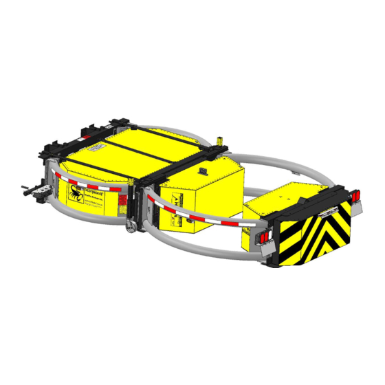
- Page 1 Scorpion II® Truck Mounted Attenuator Assembly Manual and Mounting Instruction Guide For Model: Scorpion II® Model C MASH TL-3 TMA (Excludes high reach extension) PLEASE READ ALL INSTRUCTIONS CAREFULLY BEFORE PROCEEDING WITH THE INSTALLATION Version 1.0 0800 785 744 rtl.co.nz...
- Page 2 Scorpion II® Truck Mounted Attenuator Assembly Manual and Mounting Instruction Guide (For Model: Scorpion II® Series 10000 TMA) This Manual is Available at www.traffixdevices.com 160 Avenida La Pata San Clemente, CA 92673 P/N 13082 Revision B1 Dated 1/10/2019 1...
- Page 3 This Page is Intentionally Left Blank P/N 13082 Revision B1 Dated 1/10/2019 i...
- Page 4 Scorpion II® 10000 TMA Introduction to Assembly and Mounting Instruction Guide 160 Avenida La Pata San Clemente, CA 92673 www.traffixdevices.com orders@traffixdevices.com Important: These instructions pertain only to the assembly and mounting of the Scorpion II 10000 Truck Mounted Attenuator (TMA) Model C TL-3. These instructions are only for the assembly of the models and/or accessories cited in each section.
-
Page 5: Table Of Contents
Table of Contents Page Section 1 Limitations and Warnings ………………………………………………………………………………………. Operating Instructions…………………………………………………………………………………………..2-3 Safety Instructions & Precautions…………………………………………………………………………… Notes………………………………………...………………………………………………………………………….. TMA Model C Parts List- Major Components………………………………………………………….. Section 2 Assembly of TMA Model C…………………………………………………………………………………..… Pre-Assembly Checklist/Scorpion II Registration………………………………….……………… 9 Remove Packaging/Tail Light & Side Marker Light Inspection…………………………… 10-11 Recommended* Assembly Tools………………………………………………………………….….. -
Page 6: Limitations And Warnings
Limitation and Warnings TrafFix Devices Inc. (TDI), in compliance with the Manual for Assessing Safety Hardware (MASH) recommended procedures for the Safety Performance of Highway Features. TDI contracts with ISO accredited testing facilities to conduct crash tests, evaluation of tests, and submittal of results to the Federal Highway Administration for Eligibility for Federal-Aid Reimbursement. -
Page 7: Operating Instructions
Operating Instructions Proper Operation includes knowledge of TMA use in Work Zones, both Moving and Stationary, including the proper spacing, to allow for “roll-ahead”. Before use, the Operator should have prior knowledge/ discussion of the Work Zone in which the TMA will be deployed and that the TMA model used has been tested to Test Level 3 = 100 kph/62 mph. - Page 8 To Raise (“Store”) the Unit for Transport 1. Ensure that both the truck bed and area above the rear of the host vehicle is clear. 2. Locate the desired control box, either the in-cab controller (if installed) or the plug-in. If using the plug-in, and it is not already plugged in, plug it into the socket on the TMA near the rear passenger side of the truck.
-
Page 9: Safety Instructions & Precautions
SAFETY INSTRUCTIONS & PRECAUTIONS A. Before attempting to install or operate the Scorpion II 10000 Series Truck Mounted Attenuator (TMA) this manual should be read and understood. Those areas with warnings or cautions should be carefully followed. B. Before raising or lowering the TMA the operator should check that the area around the TMA is clear and that personnel are not in or near the area. -
Page 10: Notes
Notes: P/N 13082 Revision B1 Dated 1/10/2019 5... - Page 11 P/N 13082 Revision B1 Dated 1/10/2019 6...
-
Page 12: Tma Model C Parts List- Major Components
Scorpion II 10000 TMA Model C Parts List - Major Components Item # Part # Item Description QTY/TMA 10200TL-MASH-KIT Strut Tube Assy, LH, Includes: C-Tape, Warning Labels, Side Marker Bracket Installed 10200TR-MASH-KIT Strut Tube Assy, RH, Includes: C-Tape, Warning Labels, Side Marker Bracket Installed 11400D Module D, Absorbing Scorpion II 10204... -
Page 13: Assembly Of Tma Model C
Assembly of TMA Model C P/N 13082 Revision B1 Dated 1/10/2019 8... -
Page 14: Pre-Assembly Checklist/Scorpion Ii Registration
Pre-Assembly Checklist Initial Inspection: Compare the Packing List with the original order to ensure all items have been delivered. Should any damage be found, or any items missing, contact the freight company as well as a TrafFix Devices representative as soon as possible. Scorpion II Registration 1. - Page 15 Removing Packaging for Inspection 2. Observe the warning signs before unwrapping. • Remove plastic wrap and cardboard with utility knife. P/N 13082 Revision B1 Dated 1/10/2019 10...
- Page 16 Unwrap and Inspect: Tail Lighting and Side Marker Lights 3. Remove all cardboard from lights and inspect for damage. Side Marker: Cartridge Tail Lighting: Strut P/N 13082 Revision B1 Dated 1/10/2019 11...
-
Page 17: Recommended* Assembly Tools
TMA Model C (TL-3) Assembly 1. IMPORTANT: Before beginning Assembly, please read and review the Installation Section of this manual, paying close attention to the checklist at the beginning of the section. 2. Inspect the two pallets containing the Cartridge (right) and the Strut (left), shown in Figure 1, for shipping damage and completeness against the packing list. - Page 18 Strut Assembly Overview 1. Remove the steel bands holding the Strut to the pallet. 2. Lift the Strut off the pallet using a forklift. 3. Remove mounting brackets from the pallet. 4. Reposition the Strut on the edge of the pallet. 5.
-
Page 19: Strut Assembly
Strut Assembly 1. Attach two (2) lifting straps to the Strut Diaphragm. The lifting straps must be positioned at an equal distance from the center to maintain stability when lifted. Each strap must have a minimum of 1500lb or greater load capacity. - Page 20 Strut Assembly 4. Position the strut on the edge of the pallet then slowly start lowering the Strut. 5. Once the drop jacks can safely be reached, do not lower the Strut any further. Do not let the lift straps slide off the forklift blades.
- Page 21 Strut Assembly 6. Remove the lifting straps from the Diaphragm and place them on the Back-up of the Strut. Lift the Strut until it is level. 7. Rotate and lower the swivel jacks so that the Strut is level. The Strut should no longer be supported by the forklift once the swivel jacks are deployed.
- Page 22 Strut Assembly 8. Cut and remove the zip ties that hold the hydraulic cylinders to the Strut. Remove the hair pins and clevis pins from both cylinders. *Clevis pins and hair pins are needed later on in assembly. Once the hydraulic cylinders are free of the strut, grab the end of the cylinder and lift until the cylinder is fully extended.
- Page 23 Cartridge Assembly Overview 1. Cut and remove Steel bands and cardboard from the Cartridge. 2. Remove Module A. 3. Unbolt the junction box from Module C. 4. Remove Module C from the Cartridge frame. 5. Open parts box and confirm contents. 6.
-
Page 24: Cartridge Assembly
Cartridge Assembly 1. Cut the Steel bands that are holding the components to the Cartridge. One person should be holding the components in place, while another person cuts the bands. WARNING: Watch for falling components when cutting the Steel Bands. Remove the components and the cardboard from the Cartridge. Safety Bands 2. - Page 25 Cartridge Assembly 4. Remove Module C from the Cartridge frame and set it aside for later use. Cut and remove the Steel bands that hold the Cartridge frame to the pallet. 5. Open the parts box and confirm the contents. (If there are any parts missing, document it and inform a TrafFix Devices Representative immediately.) Take out the two clevis pins and set them aside for later use.
- Page 26 TMA Model C: Strut to Cartridge Assembly Overview 1. With a forklift, align the hinges of the Cartridge to the hinges of the Strut. 2. Connect the Strut and Cartridge using hinge pins, with washers. 3. Secure hydraulic cylinders. 4. Attach the lockout arm. 5.
-
Page 27: Tma Model C: Strut To Cartridge Assembly
TMA Model C: Strut to Cartridge Assembly 1. Cut zip tie holding the power cable that is attached to the Strut. Set the power cable aside for later use. 2. Insert the clevis pin, with a washer, into the hinges connecting the Strut to the Cartridge. Tap the pin into position if necessary. - Page 28 TMA Model C: Strut to Cartridge Assembly 3. Secure the hydraulic cylinders to the Cartridge frame using the clevis pins. Secure the clevis pins with hair pins. P/N 13082 Revision B1 Dated 1/10/2019 23...
- Page 29 TMA Model C: Strut to Cartridge Assembly 4. Bolt the lockout arm on the Strut, with washers, to the Cartridge. Using an “impact gun”, fasten the bolts to the Diaphragm up to 95 ft-lbs. To ensure the proper orientation of the bolts, the bolt heads must be visible on the Cartridge side.
- Page 30 TMA Model C: Strut to Cartridge Assembly 5. Slowly lower the Cartridge with the forklift until the TMA is level. P/N 13082 Revision B1 Dated 1/10/2019 25...
- Page 31 Module C Installation 6. Install Module C. A. Lift Module C into position on the Cartridge and secure with washers and Allen head bolts. B. Use Threadlock adhesive on all bolts and tighten to a minimum of 20 ft-lbs. 7. Secure the junction box and bolt the clamp on top of Module C. Once secure, connect the power cable to the junction box.
- Page 32 Module A Installation 8. Install Module A. A. Lift Module A into position on the Cartridge and secure with bolts and washers. B. Use Threadlock adhesive on all bolts and tighten to a minimum of 20 ft-lbs. 9. Cut the zip tie that is holding the electrical cable and attach it to the cable that is located in the back of Module A. Secure the cables to the top of Module A using zip ties.
- Page 33 Complete Assembly of Model C STRUT CARTRIDGE Module A Module C Module D Module C P/N 13082 Revision B1 Dated 1/10/2019 28...
-
Page 34: Hydraulic Pump Assembly/Parts List
Hydraulic Pump Assembly 1. Fill the reservoir on the hydraulic pump with three gallons of Automatic Transmission Fluid (ATF) and attach the electrical wires (minimum gauge size of #1 battery cable for both the positive and negative hydraulic motor connections) to the motor cables. Push the “up” button on the yellow controller to raise the TMA to its stored position. - Page 35 Hydraulic Pump Parts List 1A 1B 3A 3B 2A 2B 4A 4B Item # Part # Item Description QTY/TMA 11010 12 Volt Motor w/ Hydraulic Pump - Complete 11011 24 Volt Motor w/ Hydraulic Pump - Complete 11020-12 Valve w/ 12V Coil, controls "up" 11020-24 Valve w/ 24V Coil, controls "up"...
-
Page 36: Standard Truck Mounting Installation
Standard Truck Mounting Installation Flat Bed Mount Dump Truck Mount Fast Trak Swift Connect Mount P/N 13082 Revision B1 Dated 1/10/2019 31... - Page 37 P/N 13082 Revision B1 Dated 1/10/2019 32...
-
Page 38: Standard Flatbed Truck Mounting Installation
Standard Flatbed Truck Mounting Installation Truck Installation Model C Before attempting to install the TMA to a host vehicle truck, ensure that the truck meets the following criteria: Truck weight specifications vary from state to state; however, it is recommended that the truck weighs a minimum of 15,000 lbs. - Page 39 3. With the assembled TMA in the deployed position, deploy and adjust all four jacks on a flat-leveled surface (shown in the figure below) to a height that measures approximately 14 1/2”- 15” from the underside of the TMA to the flat surface.
- Page 40 5. After proper confirmation of the backing plate being level and 90° to the horizontal surface, deploy the drops jacks and unbolt the TMA from the backing plate that is already tacked onto the host vehicle. Fully weld the backing plate on both the inside and outside of the frame rails.
- Page 41 7. Weld the angles in place at the rear of the angle. Refer to the figure below for proper welding locations. (DRIVER SIDE) 8. Install the lower bottom angle (P/N: 10356) and fully weld the angle in place. Refer to the following figure for prop- er welding locations.
-
Page 42: Dump Truck Mounting Installation
Dump Truck Mounting Installation Installation of Extension Frame Before attempting to install the TMA to a host vehicle truck, ensure that the truck meets the following criteria: Truck weight specifications vary from state to state; however, it is recommended that the truck weighs a minimum of 15,000 lbs. - Page 43 3. The extension frame comes with the right and left vertical tubes bolted in place in the right and left frame sections as shown in the first figure below. For ease of attachment to the truck, mount the extension frame to the TMA , as seen in the below second figure, and roll the TMA with the extension frame to the back of the truck,.
- Page 44 4. Once the TMA is rolled towards the back of the host vehicle, tack weld the tubes in place at the outermost and innermost four corners where the tubes touch the frame. This image below illustrates ideal tack welding locations to hold the tubes in place.
- Page 45 6. Position the splice plates, as shown here in this figure below, against the sides of the frame and the vertical tubes. Mark on the plate the position of two holes for ¾” bolts. Drill these holes in the plates and the frame. Weld the edge of the plate to the vertical tube.
- Page 46 Installing the Fast-Trak SwiftConnect™ for the Scorpion Truck Mounted Attenuator (TMA) (Follow the Directions for the Configuration received) Configuration 1 Configuration 2 Configuration 3 P/N 13082 Revision B1 Dated 1/10/2019 41...
-
Page 47: Fast-Trak Swiftconnect™ Configuration 1
Fast-Trak SwiftConnect Configuration 1 ™ (Configuration 1 is for trucks where the back end of the truck has no plate and only the truck frame rails are exposed.) PN: 11140-06 used for illustration, other lengths are installed in the same way. Adding ballast can affect the truck bed height, so it is advisable to ballast the truck before attaching the TMA. - Page 48 Rear Plate and Frame Rails will vary Truck Mount Plate Truck Mount Frame depending on height of frame rails (Rear Plate) Height from the Truck Weld Truck Mount Be sure that Truck Mount Mount Frame to the Frame to Truck Mount Plate is welded 90 degrees ground.
-
Page 49: Fast-Trak Swiftconnect™ Configuration 2
Fast-Trak SwiftConnect Configuration 2 ™ Plate already welded on truck PN: 11145-06 used for illustration, other lengths are installed in the same way. Figure 4: Exploded and assembled view of Configuration 2. Configuration 2 is for trucks where the back end of the truck has a sturdy plate already welded to the truck frame rails. Before fully welding part number 11146 truck mount to the frame rails, tack in the part to ensure proper alignment and height recommendations from the ground. - Page 50 Fast-Trak SwiftConnect Configuration 3 ™ Side mounts for truck side PN: 11155-30 used for illustration, other lengths are installed in the same way. Figure 5: Exploded and assembled view of Configuration 3. Configuration 3 is used for applications where an extension is required such as a bed overhang. Before fully welding the truck mount to the frame rails, tack in the part to ensure proper alignment and height recommendations from the ground.
- Page 51 Figure 6: Display of Fast-Trak Swift Connect mounted onto TMA This is what the TMA should look like when it is not installed onto a Truck, see Figure 6. All Jacks should be deployed and secure prior to installing the TMA onto a Truck. The Truck mounting side of the TMA should be high enough such that the hooks can go over the pins on the Truck-side mount, but the Truck side should be lower than the rear of the TMA by a couple of degrees.
-
Page 52: Support Post Installation
Support Post Installation FLAT BED SIDE SUPPORT FLAT BED CENTER SUPPORT DUMP TRUCK SIDE SUPPORT P/N 13082 Revision B1 Dated 1/10/2019 47... -
Page 53: Flat Bed Side Support Installation
Flat Bed Side Support Installation P/N 13082 Revision B1 Dated 1/10/2019 48... - Page 54 Flat Bed Side Support Installation 1. Mount the bottom support brackets (P/N 11123) on each side of the flat bed. Mark the position of the holes for the 1/2” bolts and drill these holes in the sides of the bed to fasten the bottom support bracket in to place. The outer lip portion of the bracket should rest on the topside of the bed, as shown in the figure below.
- Page 55 3. To mount the front support angle, position the angle to where the inside surfaces of the angle face away from the flat bed. Align the hole on one end of the front support angle with the hole on the support post, which is the second hole down from the top of the post.
- Page 56 5. Mount the rear support angle to the side support post, with the inside faces of the angle facing outward in the same direction as the front support angle. Pivot the rear support angle towards the rear of the truck, and mark the hole to drill and mount the rear support angle to the bed of the truck.
- Page 57 P/N 13082 Revision B1 Dated 1/10/2019 52...
-
Page 58: Center Support Installation
Center Support Installation P/N 13082 Revision B1 Dated 1/10/2019 53... - Page 59 Center Support Installation 1.To mount the Center Support (P/N 10357) onto the flat bed of the truck, center the base along the width of the flat bed. Figure 1 illustrates the proper location of the center support in reference to the width of the truck. Parts that are used to assemble the center support together are illustrated in the following figure below: 2.
- Page 60 P/N 13082 Revision B1 Dated 1/10/2019 55...
- Page 61 Dump Truck Side Support Installation P/N 13082 Revision B1 Dated 1/10/2019 56...
-
Page 62: Dump Truck Side Support Installation
Dump Truck Side Support Installation 1. Mount the support post brackets (P/N 11050) on each side of the dump truck. Mark the position of the holes for the 1/2” bolts and drill these holes in the sides of the dump truck to fasten the support bracket into place. The outer lip portion of the bracket should rest on the topside of the dump truck. - Page 63 3. To mount the support brace (11057L/11057R), position the brace to where the inside surfaces of the brace face inwards to the truck. Align the hole on one end of the support brace with the hole on the support post. Insert a 1/2” bolt to fasten one side of the support brace, as shown in following figure: *NOTE: Left Support Brace (11057L) Shown.
- Page 64 5. When the TMA is raised to the stored position, the wear plates that are mounted onto the top half of the cartridge tubes (already mounted onto TMA) should align and rest upon the top support post saddles (P/N 11040C) as shown in this figure below.
- Page 65 P/N 13082 Revision B1 Dated 1/10/2019 60...
- Page 66 TMA Limited Warranty TrafFix Devices warrants to the purchaser that the Scorpion II Truck Mounted Attenuator (TMA) is free from any defects in materials and workmanship. If this product proves to be defective in material or workmanship during the period of this warranty, TrafFix Devices will repair or replace, at its option, the defective product free of charge.
- Page 67 Notes: P/N 13082 Revision B1 Dated 1/10/2019 62...
- Page 68 Important Contact Information International Sales Corporate Office Brent Kulp TrafFix Devices, Inc. Email bkulp@traffixdevices.com Telephone 949.361.5663 160 Avenida La Pata Fax 949.573.9264 San Clemente, CA, 92673 Larry Hudoff Email orders@traffixdevices.com Email lhudoff@traffixdevices.com Telephone 949.361.5663 Telephone 954.997.9997 Fax 949.573.9250 Fax 949.325.6059 Attenuator Product Specialist Dave Evans Email...
- Page 69 Distributed By: P/N 13082 Revision B1 Dated 1/10/2019 64...
Need help?
Do you have a question about the Scorpion II C MASH TL-3 TMA and is the answer not in the manual?
Questions and answers