
Related Manuals for RTL Scorpion II C-90 MASH TL-3 Vertical TMA

Summary of Contents for RTL Scorpion II C-90 MASH TL-3 Vertical TMA
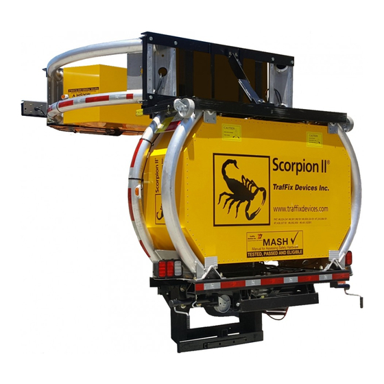
- Page 1 Scorpion II® Truck Mounted Attenuator Assembly Manual and Mounting Instruction Guide For Model: Scorpion II® C-90 MASH TL-3 Vertical PLEASE READ ALL INSTRUCTIONS CAREFULLY BEFORE PROCEEDING WITH THE INSTALLATION Version 2.3 0800 785 744 rtl.co.nz...
- Page 2 TMA Serial Number is located here. TMA No. MXXXXX Height: Bottom of Mounting Plate to Ground: This completed form must be sent to RTL for the product to be covered under warranty. Auckland RTL Auckland Wellington 31 Maurice Road, Penrose, Scorpion II C-90 Verification Form V.1.2...
- Page 3 The TMA Support Structure Rotates to Lifted Position Before the TMA will Lift to the Vertical Stored Position The TMA is Designed to Remain in the Support Structure in Horizontal Position Until Final Lifted Position and the Support Structure in TMA is Shown in the the Lifted Position Final Vertical Position...
- Page 4 Rotation of the TMA and Support Structure are Hydraulically Sequenced and is activated when the Up or Down Button is Pressed The TMA Must be Fully Deployed into the Horizontal Position Before the Support Structure Begins to Rotate to the Horizontal Position...
- Page 5 The Gold Latch Secures the TMA in the Stored Position Minimizing TMA Movement. The Latch Design is Based on a Car Hood Latch. When the TMA is Rotated into the Stored Position the Latch Engages the TMA Frame When the TMA is Deployed the Latch Disengages the Frame by means of a Sequenced Hydraulic Cylinder that Disengages the Latch Thereby Allowing the TMA to Rotate to the Horizontal Stored Position.
- Page 6 Assembly Instructions: Scorpion C-90 TMA Recommended Tools and Equipment: Recommended Safety Equipment: • Forklift with 2,500 lb minimum lifting capacity • Safety glasses • Lifting rings, straps, chain, high strength rope, etc. • Gloves • Wheel chocks • Hearing protection •...
- Page 7 Step 1. Removing the Strut From its Pallet Attach a suitable set of lifting rings/straps to the upper steel diaphragm of the Strut assembly. All rigging should have a minimum lifting capacity of 4,000 lbs (1,800 kg) and be in good condition.
- Page 8 Step 2. Removing the Strut From its Pallet Raise the Strut off of the pallet and then set it down with the mounting plate on the edge of the pallet. TITLE: Assembly Instructions Scorpion C-90 TMA SIZE DWG. NO. 1000-165 DRAWN BY: DATE: APPROVED BY:...
- Page 9 Step 3. Removing the Strut From its Pallet Continue lowering the Strut section until the jack wheels contact the ground. Insert a pair of wheel chocks (or similar object) to prevent the wheels from rolling. Lower the drop jacks until the yellow stripe is no longer visible.
- Page 10 Step 4. Leveling Strut Once the Strut section is down on all 4 wheels, the lifting straps and rope can be removed. Move the forklift to the front end of the Strut and lift from the lower tube so the jacks can be lowered.
- Page 11 Step 5. Unfolding C-90 Frame Position forklift forks a few inches below the mounting plate. 1 Carefully pull the locking latch down to release it from the latch plate. 2 After the latch has been released, the frame can be rotated down onto the forks. 3 Slowly lower the forks and reverse the forklift to lower the frame to the horizontal position. Locking Latch Locking Latch TITLE:...
- Page 12 Step 6. Install Skid Plate and Bumpers Install the bumpers and skid plate with the supplied hardware as shown below. Tighten the 1/2"-13 bolts for the bumpers until there is approximately 1/2" (13 mm) of thread exposed past the end of the nut. Recommended Tools: •...
- Page 13 Step 7. Remove Cartridge Modules Cut the banding that restrains the modules inside the Cartridge and carefully remove the modules. Don't cut the banding that holds the Cartridge to the pallet. Be sure to lift the modules one at a time and use 2 people to perform this task. Bring the forklift into position as shown below with the forks positioned 6-12" (150-300 mm) below the angle braces. TITLE: Assembly Instructions Scorpion C-90 TMA...
- Page 14 Step 8. Lower Cartridge to Horizontal Position Rock Cartridge back until the angle braces contact the forks and the Cartridge will stay in place. Slowly lower the forks and reverse the forklift simultaneously to lower the front of the Catrtridge to the ground. TITLE: Assembly Instructions Scorpion C-90 TMA...
- Page 15 Step 9. Joining the Strut and Cartridge First, loosen the turnbuckles until there is no longer tension in the steel cables that cross the top of the strut. Next, remove the eight (8) 3/4" nuts and washers from the bolts that attach the middle diaphragm to the strut tubes.
- Page 16 Step 10. Joining the Strut and Cartridge Lift the front end of the Cartridge and set thetube end plates on the bottom edge of the middle diaphragm. Align the bottom holes of the end plates with the corresponding 3/4" bolts. TITLE: Assembly Instructions Scorpion C-90 TMA...
- Page 17 Step 11. Joining the Strut and Cartridge Use the forklift to lift the rear of the Cartridige so that the top holes of the tube end plate can be aligned with the upper 3/4" bolts. Once all the bolts have been aligned with the cartridge tube endplate, the angle braces can be removed by loosening the 3/8"...
- Page 18 Step 12. Joining the Strut and Cartridge Reinstall the 3/4" nuts and washers that were removed in step 9. Be sure to install the 10122 Vertical Support Angles in the outside positions. After all of the bolts/nuts have been tightened, retighten the turnbuckles until each cable deflects no more than 1/4"...
- Page 19 Step 13. Installing the Modules Position each of the modules in place as shown below. Fasten them to the TMA using the supplied hardware consisting of eight (8) 1/4"-20 socket head screws, eight (8) 1/4" USS washers, and eight (8) 1/4" fender washers for each module. Be sure to apply a drop or two of the provided red thread locking adhesive to the threads of each screw. Recommended Tools: •...
- Page 20 Step 14. Connecting the Lighting Cables Route the lighting cables as shown in the photos below and secure with cable ties. Utilize the loop clamps installed on module C to secure the cables. Be sure to test all light functions after the connections have been made.
- Page 21 Scorpion C-90 Installation: Flat Bed Mount Prior to beginning the installation, the host truck must be at its intended operating weight. The recommended weight range is between 18,000 and 20,000 lbs [8,165- 9,070 kg] however there is no upper weight limit. Any equipment that will be permenantly installed on the truck should be present or the truck should be ballasted to represent the additional weight.
- Page 22 Scorpion C-90 Installation: Flat Bed Mount Before beginning the installation, position the truck on solid level ground. The frame rail ends should be clean and square. Remove any electrical cables that could be damaged during the installation. Place a temporary ballast weighing approximately 3,000 lbs [1,360 kg] as close to the rear of the bed as possible.
- Page 23 Scorpion C-90 Installation: Flat Bed Mount Step 2: Install Bolts and Weld 4" x 9" Angles Take note of where welding on the angles and frame is required. Grind off the powder coating from the angles and frame as needed so that a clean weld can be applied. Attach the 4"...
- Page 24 Scorpion C-90 Installation: Flat Bed Mount Step 3: Position Backing Plate and Trim 4" x 9" Angles Measure approximately 12" [25mm] up from the ground and mark a cut line at the bottom of the 4" x 9" angles. Cut off the portion of the angles that extend below the line.
- Page 25 Scorpion C-90 Installation: Flat Bed Mount Step 4: Attach TMA to Check Ride Height Check that the assembled Scorpion C-90 TMA is level and is at the proper 12 inches [25mm] off the ground (see drawing 1000-169 for reference on measuring ride height). The C-90 truck side frame should also be level with the TMA. If it is not, make adjustments to the stop bolts to bring it level (again, see drawing 100-169).
- Page 26 Scorpion C-90 Installation: Flat Bed Mount Step 5: Check Ride Height of TMA Once the TMA is securely bolted to the truck, remove the temorary ballast on the truck bed. Raise all 4 of the jacks until the truck is carrying the weight of the TMA. Inspect the TMA to verify that it is reasonably level with the truck. Proceed to take ride height measurements as outlined in drawing 1000-169.
- Page 27 Scorpion C-90 Installation: Flat Bed Mount Step 6: Welding the Backing Plate Burn holes through the 4" leg of the 4" x 9" angles in line with the backing plate holes. Fully weld the backing plate in place. Grind off all slag and weld spatter adjacent to the holes.
- Page 28 21 October, 2019 TrafFix Devices Inc is the manufacturer of the Scorpion Truck Mounted Attenuator Model C-90 (TMA). TrafFix Devices Inc reviewed the installation of the C-90 Scorpion TMA for use in New Zealand and we have designed a mounting plate (reference drawing 11174 Rev B) to be suitable for mounting the C-90 to a host truck with an installation height of between 250 and 265mm above the ground.
- Page 29 DESCRIPTION DATE ORIG. APPROVED Initial Release 9/24/12 4653A Revised & Redrawn 4/23/15 .050 .625 42.00 15.9 1066.8 .035 33.38 7.25 847.7 184.2 7.25 184.2 1.50 3.50 1.38 38.1 88.9 34.9 6.00 152.4 12.00 304.8 6.00 152.4 1.13 28.6 16 PLCS .035 UNLESS OTHERWISE SPECIFIED: ALL DIMENSIONS ARE IN INCHES[mm].
- Page 30 Scorpion C-90 Installation: Flat Bed Mount Step 7: Attaching and Leveling the TMA Attach the TMA to the truck following the same directions in step 4. Use the eight (8) provided 1"-8 x 3" bolts, locknuts, and washers to attach the TMA. The bolts should be torqued to 250 ft-lbs [340 N-m]. Once the TMA is attached, remove the temporary ballast and raise the jacks.
- Page 31 304.8±25.4mm 96" 2438.4 TITLE: Scorpion II TL-3 C-90, Overall 150.74 Dimensions, Flatbed Truck 3828.9 176.38 SIZE DWG. NO. 4480 1000-197NZ DRAWN BY: DATE: 06/07/19 SHEET 1 OF 2 Ryan Selvius...
- Page 32 4295 mm TITLE: Scorpion II TL-3 C-90, Overall Dimensions, Flatbed Truck 37.25 Bottom of C90 SIZE DWG. NO. 946.2 250 mm 1000-197NZ Mounting Plate DRAWN BY: DATE: SHEET 2 OF 2 06/07/19 Ryan Selvius...
- Page 33 Ride Height Adjustment: Scorpion C-90 Step 1. Position the TMA truck on solid level ground and lower the TMA to the fully deployed position. Measure the ride height at the rear diaphragm on both sides of the TMA. Both measurements must be 304.8mm +/- 25.4mm for the TMA to perform as designed.
- Page 34 Ride Height Adjustment: Scorpion C-90 Step 2. Raise the TMA to the fully stored position and verify that the locking latch has engaged. It is very important that the locking latch be engaged so as to prevent any unexpected movement of the TMA that could cause injury to workers. Loosen both jam nuts so the stop bolts may be adjusted. If the measurements taken in step 1 showed that the ride height was too high, turn the stop bolts clockwise which will lower the TMA.
- Page 35 160 Avenida La Pata San Clemente, CA 92673 (949) 361-5663 FAX (949) 361-9205 www.traffixdevices.com...
- Page 36 Bearing Replacement: Scorpion C-90 Frame Step 1. Position the TMA truck on solid level ground and lower TMA to the fully deployed position. Lower the drop jacks until they hit the ground, then slightly raise the TMA until the next highest pin hole on the drop jack will align and reinstall the lock pin. Lower the TMA slightly until the drop jacks are carrying weight. Lower the drop legs on the front jacks to the lowest possible position and then begin cranking the handle until the wheels contact the ground.
- Page 37 Step 2: Disconnect Strut Power Cable Before the TMA can be seperated from the C-90 frame, the lighting power cable needs to be disconnected. Remove the screws and loop clamps identified in the photo below. Disconnect the the large power cable that connects to the truck and feed it back through until it is seperated from the C-90 backup frame (PN 11502-01).
- Page 38 Step 3: Seperating the C-90 Frame Once the strut power cable is clear and the weight of the TMA is being carried by the jacks instead of the pivot pins, the C-90 frame can be seperated. Remove the keeper pins from the pivot pins (PN 10939) and the cylinder clevis pins (PN 12015-3.375). Remove the pivot pins and clevis pins as shown below. Block the casters on the TMA so it can't roll away and then pull the truck forward far enough to provide room to work.
- Page 39 Step 4: Replace Worn Bearings 1 Remove the worn bearings (four total) from the vertical pivot plates on the backup. Use a wire brush to clean the bearing holes until all debris, dirt, grease, and residues have been removed and the surface of the steel is shiny. Inspect the condition of the bearing holes for any deformation, elongation, or wear. If there is any damage or wear present on the holes, please consult with the TrafFix Engineering department for assistance before proceeding with bearing replacement.
- Page 40 Step 5: Reconnecting the C-90 Frame Once the new bearings have been installed, back the truck up to the TMA and re-align the pivot axis. When reinstalling the pivot pins, be sure to also install the provided spacer washers (PN's 12001 and 12083). These are important as they occupy the extra space and prevent the bearings from walking out. Please note, the spacer washers may need to be installed differently than depicted, their orientation is dependent on the size and locations of the gaps.
- Page 41 Inspection and Maintenance Overview: Scorpion C-90 TMA Verify function of all lights Reflective sheeting present Inspect rub bars and in good condition 10100D diaphragm Check for hydraulic Energy absorbing modules secure fluid leaks and in good condition Inspect modules for excessive damage: Replace 10215-RUBBER large dents, punctures, broken rivets mounting pads...
- Page 42 Inspection and Maintenance Overview: Scorpion C-90 TMA Clean dirt and debris from hydraulic components, locking mechanism, and pivot pins Clean electrical connections on pump and controller circuits Check that tensioning cables are sufficiently tight Check for gouges, cracks and broken welds on energy absorbing tube assemblies 12"±1"...
- Page 43 Inspection and Maintenance Overview: Scorpion C-90 TMA Inspect structural integrity of steel attenuator components Inspect 11610 bumpers for wear and cracks Inspect latch plate for excessive wear Drain hydraulic system and replace fluid TITLE: Inspection & Maintenance Overview Scorpion C-90 TMA SIZE DWG.
- Page 44 Scorpion C-90 TMA Inspection & Maintenance Schedule Before Post Each Use Weekly Monthly Annual Impact Task Verify TMA raises and lowers properly Verify that locking latch engages in stored position Verify function of all lighting Verify that reflective sheeting is present and in good condition Inspect for hydraulic fluid leaks Verify jack crank handles folded up tightly and do not hang down Verify that energy absorbing modules are secure and in good condition...
- Page 45 Before Post Each Use Weekly Monthly Annual Impact Task Verify measurements of strut and cartridge tube assemblies Inspect strut and cartridge tube assemblies for broken welds and damaged gussets Inspect atenuator steel components for deformation and broken welds Check operation of C-90 frame; verify C-90 backup pivots freely without binding Inspect truck side mounting steel for deformation and broken welds Inspect lighting and cable components for damage Inspect reflective sheeting...
Need help?
Do you have a question about the Scorpion II C-90 MASH TL-3 Vertical TMA and is the answer not in the manual?
Questions and answers