
Related Manuals for Carlson C-ALS HD


Summary of Contents for Carlson C-ALS HD
- Page 1 C-ALS HD Underground cavity scanning system Hardware manual C-ALS HD hardware manual H-5913-8500-02-C August 2023...
-
Page 3: Table Of Contents
Transit case ....................................25 2.11 Gyro Calibration jig ..................................26 2.12 Alternative deployment methods ..............................30 Maintenance and care of the C-ALS HD system ..........................31 General ...................................... 31 Preventative maintenance ................................31 Cleaning the C-ALS ................................... 32 Storing and transporting ................................32 Operational use .................................... -
Page 4: Customer Information
1.1 Dear customer The C-ALS HD system is designed to be easy to operate. However, we would ask you to take the time to read these operating instructions carefully before using the system, and to keep the manual with the instrument at all times. - Page 5 1.3.1 Manual version The document number of this manual is H-5913-8500-02-C. Compiled in August 2023. The manual is based on C-ALS HD units running firmware version 1.0.6.2 / 1.0.7.2 / 1.0.8.2. Update log H-5913-8500-02-C • Updated photos to account for design changes from C-ALS Gyro to C-ALS HD.
-
Page 6: Introduction
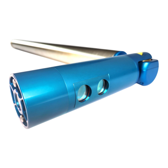
2 Introduction 1.4 Features Carlson’s C-ALS HD is a ruggedised 3D laser scanning system. With a diameter of just 50 mm, the unit is designed to be deployable through boreholes for surveys of underground voids and cavities. The C-ALS HD remotely measures the three-dimensional shape of the void and, through the accompanying software, can produce a detailed digital model of the surveyed space. - Page 7 ‘point cloud’ can be correctly geo-referenced. Carlson Scan software enables the C-ALS HD to be controlled remotely by operators in a safe location. The deployment, the borehole video and all scans can be viewed on-screen in real-time.
-
Page 8: Hardware Components
2 Hardware components This section details the full range of components that are available in a C-ALS HD system. As various models of the C-ALS have been produced and supplied, and the technology is constantly evolving and improving, some components described below may not feature in every C-ALS HD system, or may differ in some way. - Page 9 To run a full scan, the laser head requires at least 20 cm clearance from the vertical pivot, on all sides of the probe. Note that the laser head around the camera may become hot when the C-ALS HD is powered ON with the LEDs fully lit.
- Page 10 The first two functions can be carried out during the deployment at the same time as IMU readings are being taken. This negates the need to deploy a separate camera system down the borehole prior to using the C-ALS HD.
-
Page 11: Extension Piece
C-ALS HD, a separate camera should be deployed down the borehole. In this way the condition of the borehole can be checked before the C-ALS probe is deployed and put at risk. 2.2 Extension piece The extension piece is constructed of stainless steel and incorporates an adaptor for attaching Boretrak rods (Figure 5). - Page 12 Extension piece Cover piece Tightening Tightening C-ALS cable C-ALS probe Figure 6 Attaching the cover piece The main C-ALS cable must be threaded through the extension piece and connected to the probe before the extension piece is connected to the probe. The ‘scan origin’...
-
Page 13: Surface Unit
2.3 Surface unit The surface unit is housed in a durable, watertight ‘Peli’ case (Figure 8). It manages the communications and power requirements of the C-ALS probe. Figure 8 Surface unit The surface unit incorporates four Mil-Spec connectors which accept the supplied cables (Figure 9): The main C-ALS cable, which connects directly to the probe. - Page 14 C-ALS you are working with. Alternatively, contact Carlson for further information. Figure 11 C-ALS Gyro (left) / C-ALS Mk3 (centre) models should not be used with the C-ALS HD surface unit. These C-ALS probes would have been supplied with a yellow surface unit (right).
-
Page 15: Main C-Als Cable
2.4 Main C-ALS cable The main C-ALS cable delivers power to the probe, enables two-way data communications and carries the video signal from the borehole camera. The main cable can be supplied in various lengths, up to a maximum of 205 m. A moulded connector on one end screws into the threaded end of the C-ALS probe. - Page 16 Figure 13 Slip ring drum The short 5 m test cable runs from the connector on the outside of the drum frame to the appropriately sized Mil- Spec connector on the surface unit. Mil-Spec connector for cable on drum Connector for short 5 m test cable Figure 14 Connectors on the slip ring drum An ungeared handle is used to wind the cable back onto the reel.
- Page 17 2.5.1 Slip ring drum with winch A further option is a winch attachment on the side of the slip ring drum. An inbuilt brake ensures that the reel is kept under control and holds fast under load. To disengage the brake and allow free unspooling, fully unscrew the handle hub to expose the retaining thread. The handle can be detached from the handle hub.
- Page 18 Slide gear lever to change gear Figure 17 Sliding the gear lever to change to a lower gear Note that in order to change the gear, you may need to turn the handle until the gear lever engages. In addition, if there is a load on the winch, you may need to briefly take the weight off the winch in order to change the gear.
- Page 19 Figure 19 Drill with 1/4" socket attachment Using a drill, the winch can be raised around 13 m / minute. Figure 20 Using a drill to operate the winch P a g e | 19...
- Page 20 Note: when using a hand drill, it should be set to the highest clutch setting in conjunction with the ‘screw’ symbol. Do not use the drill settings showing a ‘drill bit’ or a ‘hammer’ symbol. An incorrect selection could cause injury or damage to the equipment. It is the user’s responsibility to select and correctly operate the drill equipment and to correctly manage P a g e | 20...
-
Page 21: Battery Pack
2.6 Battery pack The C-ALS HD requires a 11.5 Vdc to 15 Vdc power source. This can be supplied from a mains power adaptor or a third-party battery (see section 2.7). However, a dedicated battery pack is also supplied with the system (Figure 21). -
Page 22: Alternate Power Cables
2.7 Alternate power cables The C-ALS HD requires a 11.5 Vdc to 15 Vdc power source, input into the surface unit. The power can be provided by the supplied Carlson battery (see section 0) or by a third-party battery or from a mains power adaptor. -
Page 23: Ethernet Cable
However, there may be some circumstances where it is still advisable to use Boretrak rods to stabilize the probe during deployment and during the scanning process. Using rods with a C-ALS HD system ensures that the probe cannot exceed the 400°/sec maximum rotation rate during a deployment. - Page 24 ‘twist’ in the rods, and that all nuts and bolts and connecting pins are in place and secure. Should any rod approach end-of-life, become non-functional or damaged, stop using it immediately and request a replacement from a Carlson-approved source. P a g e | 24...
-
Page 25: Transit Case
2.10 Transit case The C-ALS and accessories are supplied in rugged transit cases to protect the system from damage and from the environment. Figure 29 C-ALS probe and extension piece in their transit case The probe and extension piece are grouped together in a ‘rifle’ case for easy shipping and transit on-site (Figure 29). -
Page 26: Gyro Calibration Jig
2.11 Gyro Calibration jig A gyro calibration jig is supplied with all C-ALS HD systems. When in use, the gyro must be calibrated at the start of every survey session. The calibration performs two functions: • The probe is held absolutely stable during the calibration, which allows the C-ALS to monitor and model any systematic drift in the gyro without having to account for any noise from movement or vibration. - Page 27 Figure 32 Calibration jig end-piece The calibration jig is designed to be dismantled for storage and transit. The end-pieces can be disconnected by unscrewing the two end-bolts. Figure 33 Removing the end-pieces With the end-pieces disconnected, use the bar on its own for vertical calibrations. The adaptor pin in the centre of the bar is the same as that on a lead Boretrak rod (Figure 33).
- Page 28 Figure 34 Adaptor pin for vertical calibrations Figure 35 C-ALS hanging from adaptor for vertical calibration The bar can sit on the collar with the probe in the hole. There are additional threads on either end of the bar for the prisms (Figure 36).
- Page 29 Figure 36 CALS probe in a borehole on a vertical calibration jig - showing direction of reference azimuth Alternatively, if the ground is suitable, keep the end-pieces fitted and stand the jig over the collar (Figure 37). Figure 37 Vertical calibration with end-pieces in place Once the vertical calibration is complete, detach the C-ALS probe from the bar and commence the deployment.
-
Page 30: Alternative Deployment Methods
2.12 Alternative deployment methods The C-ALS HD has been called on to tackle such a variety of applications in a wide range of environments that occasionally the standard deployment methods have not been sufficient. For this reason, Carlson has worked with a number of companies to produce methods of deployment suitable for specific operations. -
Page 31: Maintenance And Care Of The C-Als Hd System
In addition, you should carry out regular functional testing of the system. Detect and report damage, malfunctions or poor performance to Carlson or a local Carlson representative. Arrange a yearly calibration for your C-ALS HD system to ensure that it is kept in optimum condition and to ensure the highest possible quality of data. -
Page 32: Cleaning The C-Als
3.3 Cleaning the C-ALS Always ensure that the C-ALS HD and all accessories are thoroughly cleaned and dried before packing them in the transit case after a deployment. Use clean water to remove mud, grit and other materials from the main body of the probe after use. -
Page 33: Operational Use
4.2 System limitations 4.2.1 Environmental protection The C-ALS HD is waterproof up to a depth of 1 m. It can move mechanically in waterlogged environments but will not produce data in these circumstances. The surface unit is not watertight when its lid is open. It is thus advisable that the lid should be closed once the unit has been switched on. - Page 34 4.2.4 Mechanical If the C-ALS HD is deployed down a borehole, then the laser head and the rotating horizontal shaft must be free of the hole to allow unrestricted motion but must not be so far down the borehole that its full-length flops out of the borehole.
-
Page 35: Als Hd Specifications
905 nm Divergence <2 milliradians Maximum average power 20.5 μW Accuracy +/- 5cm (under Carlson test conditions) Resolution 1 cm Minimum range 0.5 m Maximum range to a passive target Up to 150 m (to Kodak white card - 90% reflectivity) - Page 36 Physical data Construction Machined aluminium and stainless steel Probe IP67 Environmental protection Surface unit (lid closed) IP67 Probe -10° C to +60° C Operating temperature Surface unit 0° C to 50° C Probe -25° C to +75° C Storage temperature Surface unit -25°...
-
Page 37: Safety Information
All batteries contain highly reactive, poisonous and corrosive chemicals, which are hazardous if released due to physical damage. Should the battery or battery charger approach end-of-life, become non-functional or damaged, stop using it and request a replacement unit from a Carlson-approved source. P a g e | 37... -
Page 38: Product Information
Carlson has made considerable efforts to ensure the content of this document is correct at the date of publication but makes no warranties or representations regarding the contact. Carlson excludes liability, howsoever arising, for any inaccuracies in the document. - Page 39 Information to the user (47CFR section 15.21) The user is cautioned that any changes or modifications not expressly approved by Carlson or authorised representative could void the user’s authority to operate the equipment. Information to the user (47CFR section 15.105) This equipment has been tested and found to comply with the limits for a Class A digital device, pursuant to part 15 of the FCC Rules.
- Page 40 WEEE directive The use of this symbol on Carlson products and/or accompanying documentation indicates that the product should not be mixed with general household waste on disposal. It is the responsibility of the end user to dispose of this product at a designated collection point for waste electrical and electronic equipment (WEEE) to enable reuse or recycling.
Need help?
Do you have a question about the C-ALS HD and is the answer not in the manual?
Questions and answers