
Subscribe to Our Youtube Channel
Related Manuals for Carlson FiX1


Summary of Contents for Carlson FiX1
- Page 1 FiX1 automated stockpile monitoring system installation manual FiX1 manual - H-9944-8070-1-B March 2021...
-
Page 3: Table Of Contents
Determining the best location on-site ............................24 Installing the mounting plate ............................... 28 Surveying in the mounting plate ..............................29 Attaching the FiX1 to the mounting plate ............................ 30 Mounting the cell phone and Wi-Fi antennae ..........................31 Power connection ..................................32 Networking the FiX1 ..................................... - Page 4 Processing ....................................47 Areas of Measurement ................................48 Hub-and-spoke installations ............................... 48 Verification ....................................48 FiX1 web application – introduction ..............................50 Remote updates and support ..............................50 User access ....................................50 Web application UI ..................................51 FiX1 Web application – Scans ................................53 Scanning ....................................
-
Page 5: Customer Information
This manual has been compiled with care. However, should you discover any errors, we would be grateful if you could contact Carlson directly. For any feedback or comments, or if there are questions about the FiX1 system which are beyond the scope of this manual, contact Carlson. -
Page 6: Fix1 System Overview
2.2 Operation This section gives an initial overview of the setup and operation of the FiX1. Each stage is dealt with in greater depth later in this manual. P a g e | 6... - Page 7 2.2.1 Installation During the initial installation of the FiX1 by trained staff, the unit is secured in position above the stockpiles to be scanned. The FiX1’s position should give the clearest possible view of the area of interest. Once installed, the FiX1 is surveyed in place on the site’s local coordinate system. This ensures that all data collected by the FiX1 is correctly georeferenced.
- Page 8 You may setup a data connection to the FiX1 in a variety of ways. The recommended configuration is to connect the unit to the local area network by Ethernet cable so the FiX1 can be accessed conveniently from any device on the network.
- Page 9 Figure 6 Connection using the cell phone network Once there is a successful connection to the FiX1, you can access the web application which is run from the processor onboard the FiX1. This is also where all computations are run, and all data is stored. No additional software is required on your laptop or mobile device.
- Page 10 2.2.3 Scanning and results Once fully mobilised, the FiX1 runs a laser scan across the area of interest. This can take place at scheduled times, or on demand. When carrying out a scan, the body of the FiX1 rotates horizontally at a relatively slow speed, while at the same time the laser head rotates vertically at a higher speed.
- Page 11 Figure 9 Gridded surface created from the raw point cloud The volume is reported on the FiX1’s web application and is visible, along with historical data, to anyone logging on to the system.
-
Page 12: Single And Multiple Unit Installations
FiX1. However, other sites may have stockpiles spread out over larger areas. In this case some parts of the stockpiles may be obscured from the line-of-sight of a single FiX1 unit, or some parts of the site may be beyond its maximum range. - Page 13 LOCAL AREA NETWORK SPOKE SPOKE Figure 12 Three FiX1 units in a hub-and-spoke installation P a g e | 13...
-
Page 14: Fix1 Components
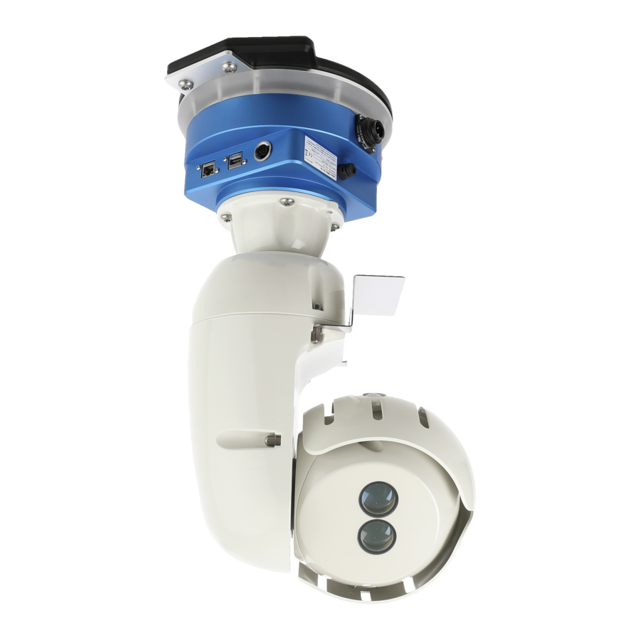
3 FiX1 components The hardware components of a FiX1 system are described below. 3.1 FiX1 unit The FiX1 consists of a laser head which pivots vertically on the body of the unit which in turn pivots horizontally on the FiX1 base. Mounting... - Page 15 3.1.1 Laser head The laser head is where the FiX1’s laser is housed. The laser head spins vertically on the vertical pivot, by which it is attached to the FiX1 body. Sun shield Receiving optics Transmitting optics Vertical pivot Figure 14 FiX1 laser head The measuring laser is an infra-red ‘time of flight’...
- Page 16 All connectors on the FiX1 base are environmentally protected to a rating of IP67. The serial number sticker is also located on the FiX1 base, next to the fuse cover. Quote the serial number during any contact you have with Carlson concerning your FiX1 unit.
- Page 17 3.1.4 SD card A 64GB Micro SD card is supplied installed into every FiX1 unit. There should be no reason to remove or change the card. However, in case this is required, the card must be formatted to Linux's ext4 file system.
- Page 18 Blue – blinking Error Red - solid 3.1.7 FiX1 baseplate The FiX1 baseplate is at the base of the FiX1 Unit. The baseplate attaches to the separate mounting plate which, in turn, is directly attached to the building superstructure. FiX1 baseplate...
-
Page 19: Mounting Plate
The mounting plate is designed to be permanently or semi-permanently fixed to the site superstructure. The FiX1 can then be easily attached once the mounting plate is in place. The FiX1 can also be easily detached from the mounting plate, if required for site operations or for servicing. -
Page 20: Ethernet Cable
The Ethernet cable supplied is a standard Cat-5e cable with RJ45 connectors. The Ethernet cable is 2 m long and can be used for testing the system before it is mounted. When the FiX1 is in position on-site, you will usually require a much longer Ethernet cable. The length will depend on where the FiX1 is mounted in relation to the nearest network connection point. -
Page 21: Wi-Fi And Cell Antennae
The two supplied antennae are identical and work on the frequency 700-2700Mhz. Whether an antenna is used for Wi-Fi or cell connection will depend on which connector on the FiX1 base the antenna is plugged into. Each antenna incorporates a mounting bracket to allow attachment to the site superstructure. -
Page 22: Transit Case
3.7 Transit case All components of the FiX1 system are contained within a dedicated transit case. The case ensures the system is protected from shocks and vibrations. Figure 23 FiX1 system in transit case When the lid is closed and the latches are snapped in place, the case is both dust tight and watertight (IP67). -
Page 23: Hardware Checks And Preventative Maintenance
-40° C to + 50° C. When handling the FiX1, use two hands to support the system by the base and body of the unit. Do not carry the unit by the head and do not put strain on the vertical or horizontal pivots. -
Page 24: Locating And Installing The Fix1 Unit
5 Locating and installing the FiX1 unit The results that are achieved by the FiX1, and the safe and reliable running of the system, are fully dependent on the correct installation and mobilization of the system on the customer’s site. This installation must be carried out only by authorised parties with the appropriate product training certified by Carlson. - Page 25 For many locations, a single FiX1, suitably positioned, can provide full coverage of the area of interest. However, if the footprint of the area of interest is beyond the working range of the FiX1 laser, or if the relative height and position of the FiX1 and the stockpiled material do not allow full line-of-sight coverage of the top surface of the stockpiles, multiple FiX1 systems may be required.
- Page 26 Each FiX1 location must be correctly geo-referenced in relation to each other so that the scans are able to form a single, cohesive surface from which a volume can be computed. Any errors in the registration of the scans will lead to errors in the computed volumes.
- Page 27 5.2.6 Power availability The FiX1 system must be supplied with ‘clean’ mains power from 85 to 265 V ac. Ensure that there is a clear cable run from the power source to the FiX1. 5.2.7 Data connection A robust data connection is required to facilitate two-way communications with the operator.
-
Page 28: Installing The Mounting Plate
FiX1 can be easily attached to, and removed from, the mounting plate, once it is in place. If it is likely that the FiX1 may be used in more than one location, Carlson recommends that multiple mounting pates and cable runs are installed and left in place. -
Page 29: Surveying In The Mounting Plate
Figure 26 The mounting plate reference line for establishing heading Note that for this heading to be meaningful, it must be related to the orientation of the FiX1 on the mounting plate. The FiX1 can be mounted in one of two positions on the mounting plate, 180° rotated from each other. In Figure 27, note the relative positions of the power connector and Ethernet connector in relation to the direction surveyed. -
Page 30: Attaching The Fix1 To The Mounting Plate
Power connector Figure 27 Looking up to a FiX1 which is mounted above and hanging down. Survey direction shown by the red arrow. Surveyed values are entered into the Calculation section of the web application (see section 7.5.1). 5.5 Attaching the FiX1 to the mounting plate With the FiX1 mounting plate installed and surveyed, the FiX1 unit can be fixed in place. -
Page 31: Mounting The Cell Phone And Wi-Fi Antennae
Lift the FiX1 unit up to the mounting plate, thread the guide pins into the guide holes on the underside of the FiX1 baseplate and twist the FiX1 unit clockwise. The FiX1 is now held temporarily in place by the guide pins. -
Page 32: Power Connection
Position the antenna over the mounting hole and stick it to the panel, applying firm pressure. Assemble the nut and washer form under the panel and tighten fully. 5.7 Power connection The FiX1 requires a stable mains power supply at 80-265 Vac. The power requirement is 80 W. P a g e | 32... -
Page 33: Networking The Fix1
FiX1 set to use a Dynamic IP address, • reserve a fixed IP address on your network router to ensure the FiX1 unit always uses the same address. • However, this setup not always practical or desirable. Ultimately, the connection used on any particular site will depend on a number of factors. -
Page 34: First Connection To The Fix1
In case you have trouble establishing a connection to the FiX1 at any time, a recovery mode is built into the unit. This may be useful when first setting up the FiX1, but it is primarily to allow emergency access to the FiX1 if the IP address has been changed, forgotten or if there are other reasons why no connection can be made to the unit. - Page 35 Figure 31 FiX1 recovery mode SSID in the Windows Wi-Fi manager The Wi-Fi access point SSID is the serial number of the FiX1. In the case above, this is 190737. Select the appropriate entry in the list of Wi-Fi networks and click Connect to connect to the FiX1.
-
Page 36: Connection Options
PC is assigned an IP address when it is connected to a company’s network. When the FiX1 is connected to a network, find the IP address of the system by using a tool such as Mac Scanner (see section 5.8.1). Enter this IP address into your web browser. - Page 37 Enter the selected IP address into your web browser. With a static IP address set, you can also connect the FiX1 directly to your PC when the PC is not connected to any network. Connect an Ethernet cable between the FiX1 and your PC.
- Page 38 Note: before changing any settings in this window, make a note of how they are currently configured. Select Use the following IP address. Enter a fixed IP address for your PC. The entered IP address should be the same as that of the FiX1, other than P a g e | 38...
- Page 39 In the example above, the FiX1 was 192.168.1.7 so the PC is being set to 192.168.1.1. Set the Subnet mask to 255.255.255.0. Click OK. Your computer is now set on the same network as the FiX1. You will lose connection to any other network to which you were previously connected.
- Page 40 To connect wirelessly to a network, in Network setup options > Wi-Fi settings, set the radio button to Wi-Fi. Click Apply Network Settings. Allow time for the FiX1 to search for networks. The local networks appear in the Available networks list. Click the network to which you wish to connect.
- Page 41 6.4.2.2 Wi-Fi access point mode Switch the FiX1 to access point mode to enable a FiX1 to act as a Wi-Fi access point. Mobile devices are then able to connect directly to the FiX1. When switched to access point mode, the FiX1 is also connected to the local network via an Ethernet cable. In this case, other FiX1 units in Wi-Fi range may connect to the local network through the first FiX1’s access point...
- Page 42 FiX1 access point. 6.4.3 Cell connection The FiX1 incorporates a cell phone SIM card appropriate for your region. This enables you to connect to the FiX1 through the cell phone network. This sets up a connection completely independent of the site network.
- Page 43 SIM card, as well as all admin and contact with the network provider. With the FiX1 sat upright, the SIM card sits in the lower card slot. The SD card sits above it. The SIM card slot directly accepts a micro SIM card. If you have a nano SIM card, insert the card into an adaptor to enable it to fit in the FiX1 card slot.
- Page 44 To use a dynamic IP address, in the Network setup options > Cellular Settings, set the mode switch to Dynamic. An IP address will be automatically assigned to the FiX1 by the cell phone network. P a g e | 44...
-
Page 45: Hub-And-Spoke Installations
6.5 Hub-and-spoke installations An installation combining more than one FiX1 unit operating together is a hub-and-spoke installation. In such a setup, every FiX1 unit must be connected to the same network. One unit is designated the ‘hub’ and all other units are the ‘spokes’. The hub is provisioned with a list of IP address for all the spokes in the installation (see section 7.5.6). -
Page 46: Remote Support
A Remote Support check box is located in the Network setup options page. When ticked, this function allows Carlson to remotely support the FiX1, both through access to the Web UI, and through direct SSH access to the FiX1 computer. -
Page 47: Volume Computations
The scan from the FiX1 must cover the entire area of interest, encompassing all sides of the stockpile(s) which are to be measured. If the positioning of the FiX1 with respect to the stockpiles means that part of a stockpile is obscured, then the FiX1 has to make the volume computation using only the data available to it. -
Page 48: Areas Of Measurement
When a scan is activated, the hub sends a scan command to the spokes, together with an empty grid. Each spoke runs a scan, fills the grid with elevations and returns the grid to the hub. The hub consolidates data from all FiX1 units in the network, cleans the data and computes a single volume (or single set of volumes if different Areas of Measurement are being used) from the resulting grid surface. - Page 49 • The uploaded base surface can be downloaded as a TIN file. In hub-and-spoke systems, this is available from the hub. • The raw point cloud is available as a LAS file. In hub-and-spoke systems, these files are held on each individual unit, whether it be a hub or spoke.
-
Page 50: Fix1 Web Application - Introduction
8 FiX1 web application – introduction All the software required for basic control of a FiX1 is contained on the unit itself in the form of a web application. This application is accessible via a web browser. Chrome, Firefox, Opera and Safari are all fully supported. No other software is required to operate the FiX1 system. -
Page 51: Web Application Ui
All other functionality is hidden for a user. 8.3 Web application UI The first time you connect to a given FiX1, the login screen is encountered. Figure 49 Log-in screen Enter the username and password as per your access status. This manual assumes you have administrator access to the FiX1. - Page 52 Settings: provides configuration tools to setup scanner operational parameters. See section 7.5. • Language: switch between multiple translations of the web application. See section 7.6. • Click one of these buttons to access different areas of the web application. The Scan page is the home page and is encountered when logging in to the web application.
-
Page 53: Fix1 Web Application - Scans
9.1 Scanning FiX1 scans can be scheduled in advance through the Schedule page. You can also start a scan manually from the Scan page. If any scans have been scheduled, the Next Scan frame shows the next scan that has been scheduled. -
Page 54: Scan List
7.7). As more scans are run, the list of scans retained by the FiX1 grows. At the bottom left of the Scan list, use the Per page drop down tool to select the number of scans to be shown on each page. - Page 55 9.2.2 Download Click Download to access a sub menu which lists the downloads available for each scan. Figure 53 Download options Binary: includes all raw data, without calibration adjustments or filtering. Open in Carlson’s P3D for • troubleshooting and data analysis.
- Page 56 Full report: a full report for troubleshooting and analysis including information about all parameters used to run or reprocess the scan. PDF report: a full report in PDF format. • Figure 54 PDF report The PDF report includes: • FiX1 serial number(s) Company name • • Site name Date and time of scan •...
-
Page 57: Scan Graph
Return to the original scan if further reprocessing is required. 9.3 Scan graph The Scan graph shows, in graphical form, the computed volumes of the most recent scans completed on the FiX1. P a g e | 57... - Page 58 ‘Maximum’ Scan graph reference line icon Individual scan detail from mouse roll over Reference ‘Minimum’ graph reference line Figure 55 Scan graph In the top right of the Scan list is an icon. Click the icon to toggle between the Scan list and the Scan graph (see section 7.3.2).
-
Page 59: Fix1 Web Application - Schedule
10 FiX1 web application – Schedule Scans can be scheduled in advance, either individually, or on a regular, recurring basis. The Schedule page displays a calendar detaining all scheduled scans. Figure 56 Schedule Use the drop-down list at the top of the page to choose whether the calendar is displayed by Month, Week or Day. - Page 60 • When the time of a scheduled scan arrives, the scan starts automatically if the FiX1 is powered on. If you connect to the web application during a scheduled scan you will see the Active frame on the Scan page displaying the current scan status.
-
Page 61: Fix1 Web Application - Settings
The settings screen contains all parameters for configuring the setup and manner of operation of the FiX1. After the FiX1 has been fully installed and is working to the satisfaction of the customer, the end user should rarely have to enter the Settings page. -
Page 62: Information
Weight Computation: to enable a weight to be computed, enter the known density of the stockpiled • material. The Density is used to convert from volume using the formula Weight = Volume x Density. 11.2 Information The Information section contains details of the current status of the FiX1 unit. P a g e | 62... - Page 63 The web application software is being constantly updated with improvements and new features. Updates to the software can be remotely distributed from Carlson to any FiX1 on a network which has access to the world wide web. A FiX1 can be configured to automatically receive regular updates whenever they become available.
-
Page 64: Scanner
11.3 Scanner When the FiX1 is scanning, the body of the FiX1 rotates horizontally at a relatively slow speed, while at the same time the laser head rotates vertically at a higher speed. The laser itself is firing constantly at a pre-determined rate. - Page 65 The Vertical coverage slider determines the vertical extents of the scan. 180° vertical coverage would survey everything up to a horizontal plane from the FiX1. The drawing to the right shows a 70° angle. The selected angle should ensure that the whole area of interest is included in each scan.
- Page 66 The Scan line interval slider determines the distance between each radial line that is scanned. In effect, this controls the speed that the FiX1 is turning horizontally in relation to the vertical spin of the laser head. Figure 64 Scan line interval 11.3.5 Head rotation speed...
-
Page 67: Reporting
11.3.6 Laser pulse rate The Laser pulse rate slider determines the speed at which the laser is firing as the head turns. Usually this setting is left at the minimum value of 5,000 Hz (5,000 measurements per second). However, for larger scan areas, this value may be increased to ensure sufficient point density at longer distances. - Page 68 11.4.1 Email alert users Reports can be sent out to defined email addresses after every scheduled scan or after thresholds are triggered. To add an email address, click Add user. Enter the email address in the Email field. Click Add user again to add subsequent email addresses.
-
Page 69: Geo-Referencing
11.5 Geo-referencing After the FiX1 mounting plate has been installed in its permanent location, and before the FiX1 unit is attached, the mounting plate is surveyed in using the site coordinate system. This must be the same coordinate system as that used to position the Bottom surface which is used as the base for volumetric computations (see section 7.5.1.4... - Page 70 FiX1 (see section 5.4). Figure 70 Azimuth of the mounting plate for a hanging FiX1 – seen from above (left) and looking up from below(right) In Figure 70, note the relative positions of the power connector and Ethernet connector in relation to the direction surveyed.
-
Page 71: Surfacing
• For most applications the FiX1 is installed hanging down. In this case the Mounting plate orientation switch should read Base plate up. If the FiX1 is installed upright, the switch should read Mounting plate down. Figure 73 Mounting plate up (left), mounting plate down (right) 11.6 Surfacing... - Page 72 TIN or DXF surface file from your computer and click Open. The file is uploaded to the FiX1. This may take a few minutes depending on the size of the file. When it is complete, the uploaded file appears in the Base surface drop down list.
- Page 73 (Z) value of each point along the polyline is ignored for the purposes of the establishment of the regions. Each polyline in the file must have at least three vertexes. If the polyline is not closed, the FiX1 will close it by automatically.
-
Page 74: Network Setup Options
(steepest) angle of repose of the different materials. 11.7 Network setup options The Network setup options allows you to configure the way that you connect to the FiX1 unit. See section 5.8 for more information on the different connection options. - Page 75 Note, take great care when entering any new configuration of network settings. Incorrect entries may cause connection to the FiX1 to be lost. In this case, you may need to use the recovery mode to reestablish contact with the FiX1 (see section 5.8.2).
- Page 76 Consult your IT department for advice on the values to enter for each of these fields. Click Apply network settings to activate any changes. The IP address – fixed or dynamic – can be entered into the address bar of a web browser to access the FiX1 web application.
- Page 77 To use the Wi-Fi client mode, select Use Wi-Fi connection. Figure 81 Wi-Fi enabled, client mode All available networks within range of the FiX1’s Wi-Fi antenna appear in the Available networks list. Click the network to which you wish to connect.
- Page 78 Consult your IT department for advice on the values to enter for each of these fields. Click Apply network settings to activate any changes. The IP address – fixed or dynamic – can be entered into the address bar of a web browser to access the FiX1 web application.
-
Page 79: Management System
To set up a hub-and-spoke installation, select one unit to act as the hub and open the web application of this FiX1. Click Mesh and in the drop-down list select Hub. All spokes in the system must be added to the list. Identify the IP addresses of all FiX1 units which will be acting as spokes. -
Page 80: Calibration
Care should be taken not to tamper unnecessarily with settings in the Calculation section. Typically, these values are determined and configured on installation of the FiX1. Thereafter there should be no need to adjust the values as long as the FiX1 is installed in the same location. - Page 81 Tilt eccentricity phase • Laser tilt angle • • Head tilt angle Carlson keep all calculated calibration values on record. The calibration values are rechecked whenever the FiX1 is back in the factory for servicing. P a g e | 81...
-
Page 82: Fix1 Web Application - Language
12 FiX1 web application – Language Click Language to select one of the installed languages in the FiX1 web application. If there is a language you would like to use which is not listed, please contact Carlson to request the additional translation. -
Page 83: Online 3D Viewer
The point clouds can be downloaded from the FiX1, but the data can also be viewed online without downloading any data. The point cloud viewer is hosted on the FiX1 and viewed in your web browser. No external software is required. -
Page 84: System Specifications
14 System specifications Laser module Laser classification Class 1 (BS EN 60825-1 : 2007 and US standards 21CFR 1040.10 and 1040.11, except for deviations pursuant to Laser Notice no. 50, dated June 24, 2007) Type InGaAs Laser Diode Wavelength (typical) 905nm Accuracy* ±10mm... - Page 85 Max measuring accuracy recorded at 50 m against Kodak white card (90% reflectivity) to 1σ. Accuracy is defined as the degree of conformity of the measured sample mean range to its actual (true) value, measured with reference to a total station under Carlson test conditions.
-
Page 86: Product Information
It is essential that the FiX1 and all accessories are operated in accordance with the instructions in this user manual and it is the responsibility of the user to ensure that, in the event of a failure of any part of the Carlson system, the equipment remains safe. - Page 87 As defined by BS EN 55011:2016 Industrial, scientific and medical equipment – Radio-frequency disturbance characteristics – Limits and methods of measurement, the Carlson FiX1 is defined as Group 1, Class A equipment. The Carlson FIX1 probe is suitable for use in all locations other than those allocated in residential environments and those directly connected to a low-voltage power supply network which supplies buildings used for domestic purposes.
- Page 88 Correct disposal of this product will help to save valuable resources and prevent potential negative effects on the environment. For more information, please contact your local waste disposal service or Carlson representative. POTREE Potree 3D renderer - http://potree.org Copyright (c) 2011-2017, Markus Schütz. All rights reserved.
Need help?
Do you have a question about the FiX1 and is the answer not in the manual?
Questions and answers