
Related Manuals for Toro 04530


Summary of Contents for Toro 04530
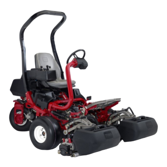
- Page 1 Form No. 3404-717 Rev A Greensmaster ® 3320 TriFlex ® Traction Unit Model No. 04530—Serial No. 316000001 and Up g014597 *3404-717* A Register at www.Toro.com. Original Instructions (EN)
- Page 2 You are responsible for operating the product properly and safely. You may contact Toro directly at www.Toro.com for product and accessory information, help finding a dealer, or to register your product. Whenever you need service, genuine Toro parts, or additional...
-
Page 3: Table Of Contents
Safety ................4 Drive System Maintenance .........39 Safe Operating Practices........... 4 Adjusting the Transmission for Neutral .....39 Toro Mower Safety ..........5 Adjusting the Transport Speed .........40 Sound Power Level ..........6 Adjusting the Mowing Speed........40 Sound Pressure Level..........6 Brake Maintenance ............41... -
Page 4: Safety
Safety • Slow down and use extra care on hillsides. Turf conditions can affect the machine's stability. Use caution while operating near drop-offs. This machine has been designed in accordance with • Slow down and use caution when making turns and when EN ISO 5395:2013 and ANSI B71.4-2012 and meets these changing directions on slopes. -
Page 5: Toro Mower Safety
• The operator must be skilled and trained in how to drive The following list contains safety information specific to Toro products or other safety information that you must know that on hillsides. Failure to use caution on slopes or hills may is not included in the ANSI standards. -
Page 6: Sound Power Level
Authorized Toro Distributor. • To ensure optimum performance and continued safety certification of the machine, use only genuine Toro replacement parts and accessories. Replacement parts and accessories made by other manufacturers could be dangerous, and such use could void the product warranty. -
Page 7: Safety And Instructional Decals
Safety and Instructional Decals Safety decals and instructions are easily visible to the operator and are located near any area of potential danger. Replace any decal that is damaged or lost. 115-8155 1. Warning—read the Operator's Manual, do not prime or use starting fluid. - Page 8 132-9548 1. Engine speed—fast 7. Reel speed—neutral 2. Engine speed—slow 8. Reel—transport 3. Lower and engage the reels 9. Reel—mow 4. Raise and disengage the reels 10. Reel—backlaping 5. Reel speed—fast 11. Move forward 6. Reel speed—slow 132-9550 1. Choke 3.
- Page 9 Battery Symbols Some or all of these symbols are on your battery 131-2046 1. Explosion hazard 6. Keep bystanders a safe 1. Double lights 3. Off distance from the battery. 2. Single light 2. No fire, open flame, or 7. Wear eye protection; smoking.
- Page 10 115-8156 1. Reel height 3. 8–Blade cutting unit 5. 14–Blade cutting unit 7. Fast 2. 5–Blade cutting unit 4. 11–Blade cutting unit 6. Reel speed 8. Slow 119-9345...
-
Page 11: Setup
Activate and charge the battery. – No parts required Install the optional oil cooler. Grass-basket hook Install the grass-basket hooks. Flange bolts Gauge bar Cutting unit (obtain from your Toro Distributor) Install the cutting units and counter Grass basket weights. Electric-reel-motor counterweight Capscrew –... -
Page 12: Installing The Roll Bar
Installing the Roll Bar Installing the Seat Parts needed for this procedure: Parts needed for this procedure: Roll bar Seat Bolt (1/2 x 3-3/4 inches) Seat wiring harness Flange-nut (1/2 inch) Procedure Procedure Note: Mount the seat in the front set of mounting holes to gain an additional 7.6 cm (3 inches) in the forward adjustment, 1. -
Page 13: Installing The Steering Wheel
WARNING CALIFORNIA Proposition 65 Warning Installing the Steering Wheel Battery posts, terminals, and related accessories contain lead and lead compounds, chemicals known to the State of California Parts needed for this procedure: to cause cancer and reproductive harm. Steering wheel Wash hands after handling. -
Page 14: Installing The Oil Cooler (Optional)
bring the electrolyte to within about 6 mm (1/4 inch) WARNING of the bottom of the fill well (Figure Incorrect battery cable routing could damage the 5. Connect a 2 to 4 A battery charger to the battery posts. tractor and cables causing sparks. Sparks can cause Charge the battery for at least 2 hours at 4 A or for at the battery gasses to explode, resulting in personal least 4 hours at 2 A until the specific gravity is 1.250... -
Page 15: Installing The Grass-Basket Hooks
5395:2013 Standards when equipped with the Weight Kit, Installing the Cutting Units Part No. 119-7129. Parts needed for this procedure: Gauge bar Cutting unit (obtain from your Toro Distributor) Installing EU Decals Grass basket Electric-reel-motor counterweight Parts needed for this procedure:... -
Page 16: Reducing The Tire Pressure
Product Overview Reducing the Tire Pressure No Parts Required Procedure The tires are over-inflated at the factory for shipping purposes. Reduce the pressure to the proper levels before starting the machine. Refer to Checking the Tire Pressure (page 25). Burnishing the Brakes g014674 Figure 10 No Parts Required... - Page 17 Figure 13 g014603 Figure 11 1. Ignition switch 4. Raise/Lower mow control 2. Choke lever 5. Throttle lever 1. Traction pedal—forward 3. Steering arm locking pedal 3. Functional-control lever 6. InfoCenter control 2. Traction pedal—reverse Choke Lever To start a cold engine, close the carburetor choke by pushing the choke lever forward(Figure 13) to the C...
-
Page 18: Infocenter Control
Ignition Switch Insert the key into the switch (Figure 13) and turn it clockwise as far as possible to the S position to start the engine. TART Release the key as soon as the engine starts; the key will move 52.2V to the O position. - Page 19 EELS NABLE a list of the recent machine enabled. faults. Refer to the Service Manual or your Authorized ETTINGS Toro Distributor for more information on the F AULTS Menu Item Description menu and the information contained there. Controls the units used on the NITS InfoCenter.
- Page 20 The delay setting represents the maximum time for the Turns the automatic ONTROL clip-control feature O raise/lower joystick to remain in the raise position to activate this feature. The factory default setting is 1 which disables Set the number of blades in LADE OUNT this feature.
- Page 21 When this icon is present there is a new log entry in the Faults menu that you or your distributor can use to identify the problem. For a list of faults, refer to your Authorized Toro Distributor or the Service Manual. g01462 6...
-
Page 22: Specifications
Before installing, removing, or working on the cutting its capabilities. Contact your Authorized Service Dealer or units, disconnect the cutting units from the power supply Distributor or go to www.Toro.com for a list of all approved by separating the cutting unit power disconnect connectors attachments and accessories. -
Page 23: Operation
Operation 1. Position the machine on a level surface. 2. Unscrew the dipstick and wipe it with a clean rag. Note: Determine the left and right sides of the machine 3. Screw the dipstick into the tube and make sure it is from the normal operating position. -
Page 24: Checking The Hydraulic-Fluid Level
Toro distributor for part numbers.) • Do not fill fuel containers inside a vehicle or on Alternate fluids: If the Toro fluid is not available, other fluids a truck or trailer bed because interior carpets may be used provided they meet all the following material or plastic truck bed liners may insulate the properties and industry specifications. -
Page 25: Checking The Reel-To-Bedknife Contact
EnviroSyn 46H Important: Mobil EAL EnviroSyn 46H is the only synthetic biodegradable fluid approved by Toro. This fluid is compatible with the elastomers used in Toro hydraulic systems and is suitable for a wide-range of temperature conditions. This fluid is compatible... -
Page 26: Checking The Torque Of The Wheel Nuts
Note: If oil leaks continue to appear, contact performance closely so that minor difficulties, which could your Authorized Toro Distributor for assistance lead to major problems, are noted and can be corrected. and, if necessary, replacement parts. -
Page 27: Checking The Leak Detector
The purpose of the safety-interlock system is to prevent 11. Start the engine. operation of the machine where there is possible injury to the 12. Move the raise/lower mow control forward to lower operator or damage to the machine. the cutting units. The cutting units should lower but •... - Page 28 3. Insert a clean rod or screwdriver into the tank neck and gently push down on the switch float (Figure 28). The alarm should sound after the one-second delay. G020736 Figure 26 Normal operation (oil warm) Figure 28 1. Solenoid-return 3.
-
Page 29: Installing And Removing The Cutting Units
Installing and Removing the Installing the Electrical Counterweights Cutting Units Secure the electrical counterweight to the existing counterweight with 2 capscrews as shown in Figure Note: When sharpening, setting the height-of-cut, or performing other maintenance procedures on the cutting units, store the cutting unit reel motors in the storage location on the front of the suspension arms to prevent damage to them. - Page 30 Note: A “click” can be heard and felt when the latches are properly locked in place. 6. Coat the spline shaft of the cutting unit motor with clean grease (Figure 34). 7. Insert the motor into the left side of the cutting unit (as viewed from the operator's position) and pull the motor retaining bar on the cutting unit toward the motor until you hear an audible “click”...
-
Page 31: Mowing
Removing the Cutting Units 1. Disconnect the cutting unit power disconnect couplers; refer to Cutting Unit Power Disconnect Connectors (page 22). CAUTION If you do not disconnect the power to the cutting units, someone could accidentally Figure 36 start the cutting unit, causing serious injury to hands and feet. - Page 32 Note: This procedure drops the cutting units to the turf and starts the reels. Important: The No. 1 cutting unit reel is delayed; therefore, you should practice to gain the required timing necessary to minimize the cleanup mowing operation. 4. Overlap a minimal amount with the previous cut on return passes.
-
Page 33: Inspecting And Cleaning After Mowing
Towing the Machine In case of an emergency, you can tow the machine for a short distance, less than 0.4 km (1/4 mile); however, Toro does not recommend this as standard procedure. Important: Do not tow the machine faster than 3 to 5 km/h (2 to 3 mph) because the drive system may be damaged. -
Page 34: Maintenance
Note: Determine the left and right sides of the machine from the normal operating position. Note: Download a free copy of the electrical or hydraulic schematic by visiting www.Toro.com and searching for your machine from the Manuals link on the home page. -
Page 35: Daily Maintenance Checklist
Daily Maintenance Checklist Duplicate this page for routine use. Maintenance Check Item For the week of: Mon. Tues. Wed. Thurs. Fri. Sat. Sun. Check the safety interlock operation. Check the instrument operation Check the leak detector alarm. Check the brake operation. Check the fuel level. -
Page 36: Lubrication
Lubrication Engine Maintenance Greasing the Machine Servicing the Air Cleaner Service Interval: Every 400 hours Service Interval: Every 50 hours—Service the air-cleaner foam element (more frequently when Lubricate the grease fitting with No. 2 lithium grease. operating conditions are dusty or dirty). 1. -
Page 37: Changing The Engine Oil And Filter
2. Remove the oil filter (Figure 42). 3. Apply a light coat of clean oil to the new filter gasket. 4. Screw the filter on by hand until the gasket contacts the filter adapter, then tighten it 3/4 to 1 turn further. Do not overtighten it. -
Page 38: Fuel System Maintenance
Fuel System Electrical System Maintenance Maintenance Replacing the Fuel Filter Servicing the Battery Service Interval: Every 800 hours (Sooner if the fuel flow Properly maintain the battery electrolyte and keep the top of is restricted) the battery clean. Store the machine in a cool place to prevent the battery from running down. -
Page 39: Locating The Fuses
Drive System WARNING Maintenance CALIFORNIA Proposition 65 Warning Battery posts, terminals, and related Adjusting the Transmission accessories contain lead and lead compounds, for Neutral chemicals known to the State of California to cause cancer and reproductive harm. If the machine creeps when the traction-control pedal is in Wash hands after handling. -
Page 40: Adjusting The Transport Speed
Adjusting the Transport Speed Adjusting the Mowing Speed The mow speed is set to 3.8 mph at the factory. Obtaining the Maximum Transport The forward moving speed can be adjusted from 0 to 8 km/h Speed (0 to 5 mph). The traction pedal is adjusted for maximum-transport speed 1. -
Page 41: Brake Maintenance
12 Burnishing Every 800 hours the Brakes (page 16). If the oil becomes contaminated, have your Toro distributor flush the system. Contaminated oil looks milky or black when compared to clean oil. 1. Clean the area around the filter mounting area (Figure 49). -
Page 42: Checking The Hydraulic Lines And Hoses
Checking the Hydraulic Lines Cutting Unit Maintenance and Hoses Backlapping the Reels WARNING WARNING Hydraulic fluid escaping under pressure can penetrate skin and cause injury. Contact with the reels or other moving parts can result in personal injury. • Ensure that all hydraulic fluid hoses and lines are in good condition and all hydraulic connections •... -
Page 43: Storage
Storage If you wish to store the machine for a long period of time, the following steps should be performed prior to storage: 1. Remove accumulations of dirt and old grass clippings. Sharpen the reels and bedknives, if necessary; refer to the cutting unit Operator's Manual. - Page 44 Notes:...
- Page 45 Notes:...
- Page 46 Notes:...
- Page 47 The Way Toro Uses Information Toro may use your personal information to process warranty claims, to contact you in the event of a product recall and for any other purpose which we tell you about. Toro may share your information with Toro's affiliates, dealers or other business partners in connection with any of these activities. We will not sell your personal information to any other company.
- Page 48 Countries Other than the United States or Canada Customers who have purchased Toro products exported from the United States or Canada should contact their Toro Distributor (Dealer) to obtain guarantee policies for your country, province, or state. If for any reason you are dissatisfied with your Distributor's service or have difficulty obtaining guarantee information, contact the Toro importer.
Need help?
Do you have a question about the 04530 and is the answer not in the manual?
Questions and answers