Table of Contents
Advertisement
APPLICATIONS
TT-16
TR-16
NEXT ASSY.
USED ON
2. THIS MANUAL IS IN ELECTRONIC FILE FORMA
1. THE ELECTRONIC FILE IS PLACED ON CD.
:
NOTES
TOLERANCES
UNLESS OTHERWISE
SPECIFIED
FRACTION
DECIMAL
ANGLE
This drawing, written description or specifi-
cation represents a proprietary product of
Telex, Lincoln, NE, and shall not be
released, disclosed, used nor duplicated
without the written permission of TELEX
CHG. NO.
LTR
A
70-000393
B
70-000444
08/23/05
DATE
DR BY
CHK BY
APPD.
PROD.
UNLESS OTHERWISE
SPECIFIED DIMENSIONS
ARE IN INCHES.
DESCRIPTION
RELEASE
Make changes to text
T (PDF)
JTN
TITLE
NH
JRC
SIZE
S
SCALE
REVISIONS
ONLY.
TELEX
TELEX COMMUNICATIONS, INC.
Lincoln, Nebraska U.S.A.
TT-16/TR-16 Manual in Electronic
Format
DWG. NO.
CODE IDENT
57010
NONE
DATE
APPD
JRC
06/23/05
JRC
08/23/05
804184-TX
1 of 1
SHEET
Advertisement
Table of Contents

Subscribe to Our Youtube Channel
Related Manuals for Telex TR-16


Summary of Contents for Telex TR-16
- Page 1 APPD. ANGLE PROD. This drawing, written description or specifi- cation represents a proprietary product of Telex, Lincoln, NE, and shall not be released, disclosed, used nor duplicated without the written permission of TELEX DESCRIPTION Make changes to text T (PDF)
- Page 2 Telex Op er at ing In struc tions TT-16 16 Channel Transmitter TR-16 16 Channel Receiver RadioCom Wireless IFB...
- Page 3 WHAT FREQUENCY BAND DOES THE TELEX SYSTEM OPERATE IN? The Telex Sys tems fea ture a syn the sized trans mit ter and a syn the sized re ceiv er op er at ing in the VHF Band be tween 64-68 MHz. See Ta ble 1 for stan dard fre quen cies avail able.
-
Page 4: Often Asked Questions
Can the re ceiver re ceive other trans mis - sions when the trans mit ter is turned off? n swer: Yes it can. Telex sys tems op er ate in the VHF Band be tween 64-68 MHz. How ever, it is not sus cep ti ble to ra dio wave skip, CB’ers or stan dard... -
Page 5: Synthesized Receiver
RECEIVER General Description TR-16 The Telex TR-16 Re ceiver is a com po nent of a sys - tem which op er ates on six teen (16) user selectable chan nels in the 64 to 68 MHz fre quency band. The re ceiv ers are de signed to be used with the Telex TT-16 Trans mit ter. -
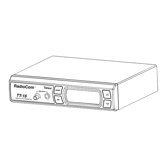
Page 6: Synthesized Transmitter
TT-16 SYNTHESIZED TRANSMITTER General Description The Telex TT-16 is a base sta tion trans mit ter which op er ates in the 64-68 MHz band and ac cepts a wide range of au dio in put lev els. Operating Features... - Page 7 Clear-Com In ter com Sys tems, Inc. TT-16 Rear Panel 1. XLR In put Con nec tor: Ac cepts bal - anced two wire Telex, RTS chan nel 1 or RTS chan nel 2. NOTE: RTS chan nel 2 is com pat i ble with *Clear-Com®...
-
Page 8: Rear Panel
RTS 1 Se lected...Line im ped ance 200 RTS 2 Se lected...Line im ped ance 200 Telex Se lected ...Line im ped ance 300 Un bal anced Au dio In put ...10K RF Power Switch...50mW in “Hi”, approx. 5mW in “Low”... -
Page 9: System Setup
Bal anced In ter com In put and Level Ad just ment With the Bal anced In ter com In put se lec tion flash ing (RTS1, RTS2, or TELEX). Use the UP and DOWN but tons to scroll to the cor rect in put. With the cor - rect in put dis played, press SET and the "Bal anced... - Page 10 1. In or der to de ter mine whether your se lected fre - quen cies have min i mum in ter fer ence, Telex rec - om mends that you first tem po rarily in stall the re ceiv ers in your pro posed set ting and mon i tor the chan nel for in ter fer ence.
-
Page 11: Headphone Jack
TR-16 with a TT-44 IFB Trans mit ter, E.D.R. must be turned off. 1) To en gage the E.D.R func tion turn the TR-16 off with the vol ume con trol thumb wheel. 2) Press and hold the SET but ton while you turn the TR-16 back on. -
Page 12: Battery Replacement
Low Bat tery Dis play BATTERY REPLACEMENT The TR-16 Re ceiver uses two (2) AA bat ter ies. When the bat ter ies are low the sound will be dis - torted. Re place weak bat ter ies with two fresh AA bat ter ies, and po si tion them in the bat tery com part - ment as il lus trated in Fig ure 9. -
Page 13: Battery Information
Antenna Placement Proper an tenna place ment prob a bly has the most ef - fect on your TELEX Wire less Sys tem’s over all per - for mance. Fol low ing the sug ges tions that fol low should re sult in “drop out free” per for mance. - Page 14 Make sure the “sig nal path” be tween the trans mit ter and re ceiver(s) is un ob structed. You should al ways be able to vi su ally lo cate the an tenna of the trans - mit ter at all times. RadioCom Telex power Monitor TT-16 WIRELESS IFB TRANSMITTER SIG NAL REACHES AN TENNA AT FULL STRENGTH WITH NO OB - STRUC TIONS.
-
Page 15: Troubleshooting
E.D.R. func tion may be en gaged on the TT-16. See set ting E.D.R. func tion on page 9. The E.D.R. fea ture can only be used with the TR-16 and must be ac tive on both trans mit ter and re - ceiver to be ef fec tive. -
Page 16: Fcc Information
The Telex TR-16 re ceiver is au tho rized un der part 15 of the FCC Reg u la tions. Changes or mod i fi ca - tions to this equip ment could void the user’s au thor ity to op er ate the equip ment. - Page 17 TELEX COM MU NI CA TIONS, INC. 12000 Port land Ave. South, Bur nsville, MN 55337, U.S.A. PN 804184 Rev. B AUG 2005 Made in U.S.A.
Need help?
Do you have a question about the TR-16 and is the answer not in the manual?
Questions and answers