Table of Contents
Advertisement
Quick Links
Operating Instructions
Silage trailers
CAREX 370 S
CAREX 390 K
SHUTTLE 370 S
SHUTTLE 390 K SHUTTLE 430 K SHUTTLE 470 K
Series:
Type:
Type of document:
As of:
Document number
CAREX 410 S
CAREX 430 K
SHUTTLE 410 S
2-134
SL11
Original operating instructions
201703 en
BTA_SL11_CAREX+SHUTTLE_201703_en
CAREX 450 S
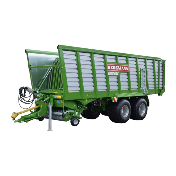
CAREX 470 K
SHUTTLE 450 S
CAREX 490 S
CAREX 510 K
SHUTTLE 490 S
SHUTTLE 510 K
Advertisement
Table of Contents


Need help?
Do you have a question about the CAREX 370 S and is the answer not in the manual?
Questions and answers