Table of Contents
Advertisement
Quick Links
Advertisement
Table of Contents

Related Manuals for GSSI FLEX NX


Summary of Contents for GSSI FLEX NX
- Page 1 User Guide MN73-362 Rev A Geophysical Survey Systems Inc. www.geophysical.com...
- Page 2 Published by Geophysical Survey Systems, Inc. 40 Simon Street Nashua, NH 03060-3075 USA GSSI, Flex NX, Nexus, GSSI Fusion, RADAN, SIR, UtilityScan, PaveScan RDM are registered trademarks of Geophysical Survey Systems, Inc.
-
Page 3: Limited Warranty, And Limitations Of Liability And Restrictions
2. The Flex NX operates with stepped frequency CW modulation in 1-40 MHz steps between 30-6000 3. The Flex NX dwell time on any one frequency does not exceed 2 microseconds. 4. The dwell time during any step of the Flex NX does not exceed 0.04 percent of the device’s minimum scan/cycle rate. -
Page 4: Fcc Class A Compliance
Geophysical Survey Systems, Inc. Flex NX /NX25 User Guide ® FCC Class A Compliance This device complies with Part 15 of the FCC Rules. Operation is subject to the following two conditions: (1) this device may not cause harmful interference, and (2) this device must accept any interference received, including interference that may cause undesired operation. -
Page 5: Table Of Contents
What’s in the Box ................................ 1 Optional Accessories ..............................2 System Specifications..............................2 Comparison of Flex NX and StructureScan Mini XT ..................3 What is NEXUS™? ............................... 4 Flex NX and GSSI Fusion™ ............................4 GPR Theory Overview ............................... 4 The Anatomy of a GPR Profile ........................... - Page 6 Project Profile ............................... 35 Transferring Data ..............................38 Wireless Transfer ..............................40 USB Transfer ................................42 Collecting Data with Flex NX ......................44 Scanning and Marking Overview ........................44 Before You Scan ............................... 44 Data Screen and Basic Collection ........................46 Top Navigation Panel .............................
-
Page 7: Introduction
For more information, visit us at www.geophysical.com. Our team of dedicated technical trainers is ready to work with users of all experience levels, and GSSI Academy classes are offered on an annual schedule. Check out the GSSI Academy offerings at www.geophysical.com/gssi-academy... -
Page 8: Optional Accessories
IP Rating IP65 (fully sealed against dust, low-pressure omnidirectional water) Battery Performance Flex NX up to 3.5 hours, NX25** up to 6 hours in ideal conditions Dimensions Flex NX: 25.3 x 13.2 x 18.9 cm (9.9 x 5.2 x 7.4 in) NX25**: 11.2 x 11.2 x 10.4 cm (4.4 x 4.4 x 4.1 in) -
Page 9: Comparison Of Flex Nx And Structurescan Mini Xt
Flex NX is what you’ve come to expect from GSSI – a cutting-edge product that is Simple, Flexible, and Trusted. Flex NX is built on GSSI’s newly completed Nexus platform, and the first in a series of industry-defining and transformative GPR systems. -
Page 10: What Is Nexus
Nexus, and its capabilities, by contacting your GSSI sales representative. Flex NX and GSSI Fusion™ Flex NX was designed with GSSI’s Fusion platform at the forefront. Our vision was to create a reporting platform that seamlessly integrated with our field devices. Fusion is the culmination of that effort. -
Page 11: The Anatomy Of A Gpr Profile
Geophysical Survey Systems, Inc. Flex NX /NX25 User Guide ® reflecting at boundaries with contrasting physical and chemical properties. The remaining waves travel deeper, reflecting from other boundaries until the waves dissipate. A receiving antenna records the reflections and plots them for display and analysis. The majority of modern commercial GPR systems use antennas containing both transmitter and receiver. - Page 12 The result is a single scan that is represented by the O-Scope. Additional scans are collected as Flex NX moves forward, resulting in a continuous GPR profile. All GPR profiles exhibit a series of flat, high amplitude bands that appear at and around the ground surface.
- Page 13 Geophysical Survey Systems, Inc. Flex NX /NX25 User Guide ® To an experienced GPR operator, the phase and amplitude of targets and layers reveals additional information to enhance data interpretation. Enabling the O-Scope display will assist with advanced interpretations. GPR energy cannot penetrate metallic targets, so a large amount of energy is reflected back to the antenna and registers as a high amplitude target.
-
Page 14: Common Gpr Uses In Concrete Scanning
Geophysical Survey Systems, Inc. Flex NX /NX25 User Guide ® Common GPR Uses in Concrete Scanning GPR is a non-destructive method that provides insight into the condition, composition, and structural characteristics of concrete elements. This helps in ensuring the safety, durability, and efficient management of concrete structures. -
Page 15: Flex Nx Hardware Overview
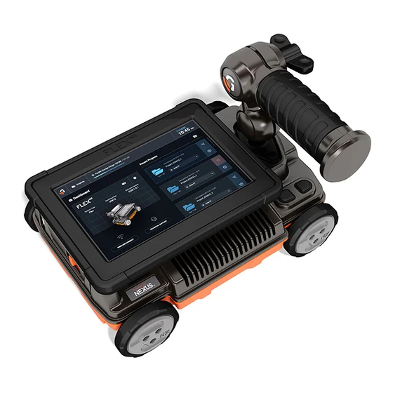
Flex NX Hardware Overview Handle Configurations The Flex NX handle is ergonomically designed to promote ease of use and maximum flexibility. The handle is highly configurable, with a wide range of adjustment angles and built-in safeguards to prevent screen damage. To adjust the handle, simply loosen the knob, reorient the handle, and tighten. -
Page 16: Battery Usage
Battery Usage The Flex NX system and NX25 satellite antenna (sold separately) each include two Lithium-ion batteries. Note: the batteries are not compatible between Flex NX and NX25, but both battery styles use the same charging station. Flex NX Battery To insert the battery, slide the battery door latch to the left and open the door. -
Page 17: Powering On Flex Nx And Nx25 Satellite Antenna
Flex NX uses near-field communication (NFC) to pair with satellite antennas. Paring a satellite antenna to Flex NX is simple. First, power on Flex NX and wait for the Main Dashboard to appear. Next, power on NX25 and observe the red indicator light. Wait for the red indicator light to flash blue, indicating that NX25 is ready to pair. -
Page 18: Using Two Gpr Antennas: Standard And Cross-Polarized
Channel 2 does not display data until it has passed the starting point of Channel 1. The two Flex NX antennas are designed to work in tandem, providing an exceptional scanning experience employing one-pass cross-polarization. Both antennas have specific strengths. The standard antenna is aligned perpendicular to the path of travel, as is common for most commercial GPR systems. - Page 19 By utilizing data from both standard and cross- polarized antennas Flex NX can better discriminate between different types of objects or materials and improve overall data resolution and accuracy. GSSI recommends scanning with both antennas active so you can view a complete picture of the slab contents.
-
Page 20: Flex Nx User Interface
® Flex NX User Interface This section will familiarize new users with the Flex NX user interface. By the end of this section, you will be able to navigate through the system, create and manage projects, and be ready to collect data. - Page 21 / 200 GB Battery Life Indicator. Displays the charge state of the currently active device. This will usually refer to the Flex NX battery, though it will show the NX25 battery if it is the active device. System Date and Time. Set the current date and time for an accurate 5/31/23 timestamp.
- Page 22 Main Dashboard: System and Support Pane Battery Life Indicator. A fully charged Flex NX battery can provide up to 3.5 hours of use. An NX25 battery delivers up to 6 hours of use. System Settings. Tap this icon to access the System Settings and Health Settings screens.
- Page 23 The Recent Projects pane displays a list of your most recently accessed project folders. When first used, your Flex NX will only have a Default Project folder. As you add more projects they will appear in this pane, ordered by most recent use.
-
Page 24: System Settings
Tap the gear icon on the Main Dashboard to navigate to the System Settings screen. Use System Settings to customize your Flex NX or NX accessory antenna preferences. This portal is the Flex NX command center for enabling or disabling Wi-Fi, lasers, and the Save Prompt. You can also modify system time and date, change the measurement units and language settings, adjust system volume and screen brightness, and assign quick actions to programmable buttons. -
Page 25: Date And Time Settings
Date and Time Settings Update the Time and Date settings using the provided calendar and digital clock display. Flex NX incorporates the day/month/year into its file naming, and thus an accurate date will lead to easier file management and record keeping. -
Page 26: Nx 25 System Settings
(Flex NX Support Page) to check for new software releases. You can also scan the QR code on the Flex NX/NX25 Quick Start Guide’s cover or use the QR code provided by the Flex NX Software Update function. MN 73-362 Rev A... -
Page 27: Health Settings: Updating Flex Nx
Health Settings: Updating Flex NX Power on Flex NX and make sure the battery is near full charge. The system will not begin the update process if the Flex NX battery is lower than 50% charged. - Page 28 Flex NX /NX25 User Guide ® Flex NX will display a USB drive screen if a USB drive is not inserted or detected. Flex NX will transfer the install package once a USB drive is detected. MN 73-362 Rev A...
- Page 29 A new screen will appear once the transfer is complete. Tap Confirm Install. Feel free to remove the USB drive; it is no longer needed. Flex NX will then install the software update and will reboot once the progress bar is full. Do not power off Flex NX during this process.
- Page 30 Flex NX /NX25 User Guide ® The system will reboot to a “Configuring Flex NX v…” screen. Do not power off Flex NX during this process. The system will reboot once more and then return to the Main Dashboard. MN 73-362 Rev A...
-
Page 31: Health Settings: Updating Nx25
NX25 update process. Tap Confirm Install to continue with the update. Flex NX will power down if this window is closed using the X. Use the QR code to view release notes for the update. - Page 32 /NX25 User Guide ® The screen will transition to a “Copying install files…” page. NX25 will still display blinking purple. After install files are copied, Flex NX will show an “Installing…” page. NX25 will still display blinking purple. MN 73-362 Rev A...
- Page 33 The next update screen shows an “installing system...” page. NX25 will still display blinking purple. Flex NX will then display an “Installing NX25 vX.XX” page. Tap Dashboard to return to the Flex NX Main Dashboard. NX25 will continue to display a blinking purple indicator light.
-
Page 34: Health Settings: Log File Download
NX25 or remove the battery until the indicator light is solid green. Health Settings: Log File Download The Log File contains system-related data to assist the GSSI technical support team. Tap Log File Download to create a .ZIP file and then transfer via USB or to a wireless device. -
Page 35: Connecting An External Viewing Device
You can then view your data on another device during data collection. Try pairing your Flex NX to a tablet for a larger viewing screen, or to a smart phone for a lighter and more portable display. - Page 36 /NX25 User Guide ® If using a computer connected to the Flex NX SSID, type the displayed URL (http://192.168.8.1:3000) into your web browser. As above, a webpage will open to a blank data collection screen and will populate once you start collecting data.
- Page 37 Geophysical Survey Systems, Inc. Flex NX /NX25 User Guide ® Screen mirroring using pinch/zoom interaction. MN 73-362 Rev A...
-
Page 38: Technical Support
® Technical Support From the Flex NX Main Dashboard, tap the Technical Support icon. Scan the QR code to open the GSSI Technical Support page. You may also call the number provided to speak with a member of our Technical Support Team. -
Page 39: Project Management
Areas of Interest within a project. Use this to your advantage on job sites with multiple working areas. Keep projects organized by creating individual project folders and Areas of Interest, and then save scan data and results into these areas. You can then upload your data to GSSI Fusion. Projects Portal Access the Projects Portal from the Main Dashboard’s Top Navigation Menu by tapping the folder... - Page 40 Create new area. Flex NX’s project management system streamlines report generation in GSSI Fusion. Make sure to spend the time organizing your projects around Areas of Interest. When you upload your projects to Fusion, your data will already be organized and ready for report creation.
-
Page 41: Project Profile
Geophysical Survey Systems, Inc. Flex NX /NX25 User Guide ® Project Profile Tap any existing folder on the Projects Portal to open the associated Project Profile. Toggle between Areas of Interest to view saved Results and Scan Data. Results will typically be screengrabs taken during data collection. Select an image in the Results section to open it in a viewer. - Page 42 Please note that deleted files cannot be recovered. Results and Scan Data cannot be moved to different Project folders; they can only be moved between Areas of Interest within a single Project. Use GSSI Fusion for greater organizational control. To manage Areas of Interest, tap the stacked 3-dot icon in the upper right corner.
- Page 43 Geophysical Survey Systems, Inc. Flex NX /NX25 User Guide ® You can also delete an Area by tapping on the Area and selecting Delete Area. MN 73-362 Rev A...
-
Page 44: Transferring Data
Scan Data are packaged into .ZIP file archives containing .DZT files (raw GPR data), user marks stored in .GSSI files, and Results images captured during data collection or Playback. Future software updates will enable the pre-packaged and organized GSSI Fusion format. - Page 45 Transfer Options 1 and 2 converge at this point and the remaining transfer process is identical. Continue data transfer by tapping one of the formats and then tap Create Zip. Flex NX will begin creating the .ZIP file and will display a progress bar. MN 73-362 Rev A...
-
Page 46: Wireless Transfer
Once the .zip file is prepared you’ll be prompted to select Mobile (Wi-Fi) or USB transfer. Wireless Transfer Tapping the Wireless Transfer option generates a QR code you can scan with a smartphone. Your device will then be connected to the Flex NX network. Tap Next. If your device cannot scan QR codes, you must manually connect to the Flex NX network. - Page 47 Geophysical Survey Systems, Inc. Flex NX /NX25 User Guide ® Scan the QR Code to open a web browser. The wireless transfer address will be added to the web browser’s address bar, and the browser will open a new page.
-
Page 48: Usb Transfer
Geophysical Survey Systems, Inc. Flex NX /NX25 User Guide ® USB Transfer Tap USB to transfer the .ZIP file to a USB device, such as a USB flash drive. A USB screen will appear if a USB device is not inserted or detected. This may also occur if your USB device is formatted incorrectly. - Page 49 Geophysical Survey Systems, Inc. Flex NX /NX25 User Guide ® Flex NX will begin transferring data once a USB device is detected. You can remove the USB device when data transfer is complete. Tap Done. MN 73-362 Rev A...
-
Page 50: Collecting Data With Flex Nx
The lasers on the side of Flex NX show the center of each antenna so you can align the onscreen backup cursors with a target. You can then accurately translate the target’s location onto the slab surface using chalk, tape, or a wood crayon. - Page 51 Geophysical Survey Systems, Inc. Flex NX /NX25 User Guide ® Select a concrete type that best represents your working conditions. This setting will affect your depth accuracy. This screen will only appear once during each scanning session. Select from Very Dry, Moderately Dry, Damp, or Wet concrete types.
-
Page 52: Data Screen And Basic Collection
Tap the Start Scan icon to begin a new scan. The icon will now have a white square at its center. The data screen will remain blank until you push Flex NX forward to begin collecting data. The profile will begin building from left to right on the screen. The filename is displayed in the Top Navigation Panel (minimized by default) and is named using the current date and an affix representing the scan number. - Page 53 Screen Grab. Tap this icon to take a screenshot of the on-screen data. The Flex NX system will save the screenshot as a PNG image file for later transfer. Screen grabs are saved to the Results section of the current Project and Area of Interest.
-
Page 54: Top Navigation Panel
Geophysical Survey Systems, Inc. Flex NX /NX25 User Guide ® Top Navigation Panel The Top Navigation panel, located at the top of the screen, can be accessed during data collection by tapping the upward arrow. Tap the arrow again to minimize the menu. -
Page 55: Side Navigation
Geophysical Survey Systems, Inc. Flex NX /NX25 User Guide ® Side Navigation Activate the Side Navigation panel by tapping the gear icon on the left side of the Data Collection screen. This panel is always accessible in the Data Collection screen before, during, or after data collection or while in Playback Mode. -
Page 56: Side Navigation: Display Panel: Color Table Options Submenu
Side Navigation: Display Panel: Color Table Options Submenu Use the Display Panel’s Color Table Options submenu to select from a list of color tables. Flex NX has five (5) color table options, including the standard grayscale option. Color tables affect scans by assigning ramped colors based on the phase/polarity and amplitude range. - Page 57 Geophysical Survey Systems, Inc. Flex NX /NX25 User Guide ® Window Options Submenu: Stacked View Stacked View displays both the standard antenna and the cross-polarized antenna The front antenna (Channel 1, on top) is standard polarized and corresponds with backup cursor and lasers.
- Page 58 Geophysical Survey Systems, Inc. Flex NX /NX25 User Guide ® Window Options Submenu: Channel 2 Selecting Channel 2 will only display data from the cross polarized antenna. Note the green back up cursor corresponds with green side lasers of the cross polarized antenna.
- Page 59 Geophysical Survey Systems, Inc. Flex NX /NX25 User Guide ® The O-scope is a visualization of the raw data collected by the GPR unit. With practice you’ll find that the O-Scope is essential for advanced analysis and aligning the horizontal Target Marking line with a target’s highest amplitude peak.
-
Page 60: Side Navigation: Depth Panel
Geophysical Survey Systems, Inc. Flex NX /NX25 User Guide ® Side Navigation: Depth Panel The Depth Panel provides three options for adjusting the dielectric constant and thereby refining your depth readings. From least accurate to most accurate, the choices are Concrete Cure, Matching, and Set Depth. - Page 61 Geophysical Survey Systems, Inc. Flex NX /NX25 User Guide ® Concrete Cure set to Moderate Dry. The yellow cursor is placed at 30.00 cm below the surface. Concrete Cure set to Damp. The yellow cursor is now located at 27.50 cm below the surface. The GPR data have not changed, but the depth scale has been updated.
- Page 62 The takeaway point is that the dielectric value can dramatically change the depth reading for a given target. The target itself is not changing its true depth, but Flex NX is using the available information to calibrate its depth scale. A more refined dielectric value will greatly improve the overall depth accuracy, leading to improved markouts and increasing safety for cutting, coring, and drilling teams.
- Page 63 Geophysical Survey Systems, Inc. Flex NX /NX25 User Guide ® Use the Matching tool on multiple hyperbolas to check your accuracy. If your results are inconsistent, you have likely crossed targets at an incorrect angle. In other cases, using Matching on a shallow target with a large diameter could skew the depth scale.
-
Page 64: Target Marking
Use the Previous Target / Next Target icons (found on the Bottom Navigation Bar) to quickly jump between multiple targets within a single scan. In the System Settings screen, try assigning the Mark function to one of the Flex NX or NX25 programmable buttons. Using the assigned Mark button during 2D collection will place a dotted vertical line in your data, but it will not place discrete target marks. -
Page 65: Additional Resources
Need more information? You can visit our Flex NX support site by scanning the QR code on Flex NX’s Technical Support Panel or by visiting us at www.geophysical.com/support/FlexNXsupport. - Page 66 Geophysical Survey Systems, Inc. Flex NX /NX25 User Guide ® laser is centered between the two small marks. Try using a ruler or another straight edge to draw straighter lines. This process results in a mark directly where the center of the antenna was when it crossed the center of the target.
-
Page 67: Data Examples
Data Examples We have compiled Flex NX data examples covering some common concrete scanning scenarios. Depending on your software version, your Flex NX system may or may not have data examples preloaded. GSSI does not recommend scanning green (freshly poured) or uncured concrete. The conductivity of immature concrete dissipates the GPR energy, resulting in greatly reduced depth penetration and data quality. -
Page 68: Wire Mesh
Geophysical Survey Systems, Inc. Flex NX /NX25 User Guide ® Wire Mesh Wire mesh, located near the top of the profiles. Note the following features: Dipping mesh at far right of the profiles. • Close spacing of targets. The hyperbolic tails overlap due to the close spacing. - Page 69 Geophysical Survey Systems, Inc. Flex NX /NX25 User Guide ® Wire mesh with smaller spacing or closely spaced rebar may prevent or greatly inhibit GPR penetration. Conversely, mesh with a larger spacing, or wider spaced rebar, may allow for deeper penetration.
-
Page 70: Rebar
Geophysical Survey Systems, Inc. Flex NX /NX25 User Guide ® Rebar Steel reinforcing bars (rebar) are, along with wire mesh, the most common targets in concrete structures. They are often the primary reinforcement for a slab, and typically run in two perpendicular directions. -
Page 71: Conduit
Geophysical Survey Systems, Inc. Flex NX /NX25 User Guide ® Conduit Conduit refers to hollow, metallic, or non-metallic pipe installed inside a slab. It is one of the most important targets to precisely locate, as it can contain live power lines or data cables. It may be placed into the slab prior to the concrete pouring. -
Page 72: Pan Decking
Geophysical Survey Systems, Inc. Flex NX /NX25 User Guide ® Pan Decking Pan decking is a corrugated metal sheet supporting concrete slabs. The concrete is poured onto the decking, providing strength and durability to the slab above. Pan deck slabs will usually only contain wire mesh without rebar, as the decking itself provides most of the reinforcement. -
Page 73: Beams And Objects Strapped To The Slab
Geophysical Survey Systems, Inc. Flex NX /NX25 User Guide ® Beams and Objects Strapped to the Slab Many concrete slabs have metal beams directly beneath them, and the beams may or may not be tied into the slab using vertical metal fastenings. Stud anchors and channel anchors are two such examples. -
Page 74: Pvc Vs. Metal Targets
Geophysical Survey Systems, Inc. Flex NX /NX25 User Guide ® PVC vs. Metal Targets A Polyvinyl Chloride (PVC) pipe or non-metallic conduit in concrete generally produces a low amplitude hyperbola of the same shape as hyperbolas from metal targets. PVC is nearly transparent to GPR, so targets inside or underneath a PVC pipe can still be visible. -
Page 75: Air Voids Under Concrete Slabs
Geophysical Survey Systems, Inc. Flex NX /NX25 User Guide ® Air Voids Under Concrete Slabs Voids in concrete, either air or water filled, produce observable targets when small and continuous layers when large and expansive. An air-filled void below concrete will produce a moderately strong, black-white-black reflection pattern. -
Page 76: Multiple Reinforcement Layers
Geophysical Survey Systems, Inc. Flex NX /NX25 User Guide ® Multiple Reinforcement Layers In structures with two layers of rebar, visibility of the second layer depends on the bar spacing in the first layer, slab thickness, and the amount of attenuation and scattering in the concrete. -
Page 77: Pt Cables
Geophysical Survey Systems, Inc. Flex NX /NX25 User Guide ® PT Cables Steel post-tensioned (PT) cables are present in some structures along with reinforcing bars. The cable strands are housed in sleeves and are ratcheted to a high tension after the concrete has been poured, increasing the strength of the slab. - Page 78 A post-tensioned cable positioned above a rebar mat. In this example the PT cables converge until they ‘cross’ over, then they diverge further along the profile. These data were collected using a single file number, and the Flex NX was moved to adjacent locations to track PT cable layout. MN 73-362 Rev A...
Need help?
Do you have a question about the FLEX NX and is the answer not in the manual?
Questions and answers