Table of Contents
Advertisement
Quick Links
OP E R AT ING MA NUA L
O
M
PE R AT IN G
A N U A L
R OOM A IR CON DIT ION E R
M U LT I S PLIT T Y PE
(2 R OOM S , 3 R OOM S , 4 R OOM S )
COOLIN G M ODE L
Indoor U nit
HS M -9E A
Outdoor U nit
HOM -19E 2A
Indoor U nit
HS M -12E B
HS M -7E B
Outdoor U nit
HOM -20E 2A
Indoor U nit
HS M -12E A
Outdoor U nit
HOM -24E 2A
Indoor U nit
HS M -9E B
Outdoor U nit
HOM -20E 3A
Indoor U nit
HS M -12E B
Outdoor U nit
HOM -32E 4A
K E E P T HIS OPE R AT ION M A N U A L
P/N 9371689012
FOR FU T U R E R E FE R E N CE
Advertisement
Table of Contents

Subscribe to Our Youtube Channel
Related Manuals for Hiyasu HSM-9EA


Summary of Contents for Hiyasu HSM-9EA
- Page 1 OP E R AT ING MA NUA L PE R AT IN G A N U A L R OOM A IR CON DIT ION E R M U LT I S PLIT T Y PE (2 R OOM S , 3 R OOM S , 4 R OOM S ) COOLIN G M ODE L Indoor U nit HS M -9E A...
-
Page 2: Table Of Contents
CONTENTS SAFETY PRECAUTIONS ........En-1 ADJUSTING THE DIRECTION OF FEATURES AND FUNCTIONS ......En-2 AIR CIRCULATION ..........En-10 NAME OF PARTS ..........En-3 SWING OPERATION ......... En-11 PREPARATION ............ En-5 MANUAL AUTO OPERATION ......En-11 OPERATION ............En-6 CLEANING AND CARE ........En-12 TIMER OPERATION .......... -
Page 3: Features And Functions
FEATURES AND FUNCTIONS AUTOMATIC OPERATION REMOVABLE INTAKE GRILLE Merely press the START/STOP button, and the unit will be- The indoor unit’s INTAKE GRILLE can be removed for easy gin automatic operation in the Cooling or Dry mode as ap- cleaning and maintenance. propriate, in accordance with the thermostat setting and the actual temperature of the room. -
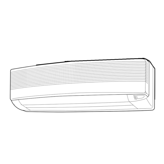
Page 4: Name Of Parts
NAME OF PARTS Fig. 1 Fig. 2 Fig. 3 Fig. 5 Fig. 4 Fig. 6 Fig. 8 To facilitate explanation, the accompanying illustra- tion has been drawn to show all possible indicators; in actual operation, however, the display will only show those indicators appropriate to the current op- eration. - Page 5 Fig. 1 Indoor Unit Fig. 6 Remote Control Unit 1 Operating Control Panel (Fig. 2) H SLEEP button 2 POWER Switch I MASTER CONTROL button 3 MANUAL AUTO button J SET TEMP./SET TIME buttons ( K Signal Transmitter 4 Remote Control Signal Receiver L TIMER button 5 Indicator Lamps (Fig.
-
Page 6: Preparation
PREPARATION CAUTION! Turn on the Power G Take care to prevent infants from accidentally swallowing batteries. Turn on the circuit breaker. G When not using the remote control unit for an extended period, remove the batteries to avoid possible leakage and Set the POWER switch (Fig. -
Page 7: Operation
OPERATION To Select Mode Operation Press the START/STOP button (Fig.6 N). The indoor unit’s OPERATION indicator lamp (red) (Fig. 3 6) will light. The air conditioner will start operating. Press the MASTER CONTROL button (Fig.6 I) to se- lect the desired mode. Each time the button is pressed, the mode will change in the following order: AUTO... - Page 8 OPERATION About Mode Operation AUTO: G Depending on the room temperature at the time operation begins, the operating mode will be switched automatically as shown in the accompanying table. Also, depending on the operating mode, the room temperature setting will cause the “standard”...
-
Page 9: Timer Operation
TIMER OPERATION Before using the timer function, be sure that the Remote Control Unit is set to the correct current time (See page 5). To Use the ON timer or OFF timer To Cancel the Timer Press the START/STOP button (Fig. 6 N) Use the TIMER button to select “TIMER (if the unit is already operating, proceed to step 2). -
Page 10: Sleep Timer Operation
SLEEP TIMER OPERATION Unlike other timer functions, the SLEEP timer is used to set the length of time until air conditioner operate is stopped. To Use the SLEEP timer To Cancel the Timer: While the air conditioner is operating or stopped, press the Use the TIMER button to select “TIMER SLEEP button (Fig. -
Page 11: Adjusting The Direction Of Air Circulation
ADJUSTING THE DIRECTION OF AIR CIRCULATION Vertical (up-down) direction of airflow is adjusted by pressing the Remote Control Unit’s AIR FLOW DIRECTION button. Hori- zontal (right-left) airflow direction is adjusted manually, by moving the Air Flow Direction Louvers. Whenever making horizontal airflow adjustments, start air conditioner operation and be sure that the vertical air direction louvers are stopped. -
Page 12: Swing Operation
SWING OPERATION Begin air conditioner operation before performing this procedure. To select SWING Operation Press the SWING LOUVER button (Fig. 6 P). The SWING indicator lamp (orange) (Fig. 3 8) will light. In this mode, the Air Flow Direction Louvers will swing automatically to direct the airflow both up and down. -
Page 13: Cleaning And Care
CLEANING AND CARE G Before cleaning the air conditioner, be sure to turn it off and disconnect the power supply cord. CAUTION! G Be sure the intake grille (Fig. 1 9) is installed securely. G When removing and replacing the air filters, be sure not to touch the heat exchanger, as per- sonal injury may result. -
Page 14: Troubleshooting
TROUBLESHOOTING In the event of a malfunction (burning smell, etc.), immediately stop operation, disconnect the WARNING! Power Supply Plug or turn off the circuit breaker, and consult authorized service personnel. Merely turning off the unit’s power switch will not completely disconnect the unit from the power source. -
Page 15: Operating Tips
OPERATING TIPS Operation and Performance In Event of Power Interruption AUTO Restart G The air conditioner power has been interrupted by a G If a power failure occurs during TIMER operation, the timer power failure. The air conditioner will then restart auto- will be reset and the unit will begin (or stop) operation at matically in its previous mode when the power is restored. -
Page 16: Specifications
SPECIFICATIONS MODEL INDOOR UNIT HSM-12EA HSM-9EA OUTDOOR UNIT HOM-24E2A HOM-19E2A TYPE COOLING MULTI SPLIT TYPE POWER 220-240 V ~ 50 Hz OPERATING INDOOR UNIT 12E + 12E 9E + 9E COOLING CAPACITY [kW] 3.45-3.50 6.9-7.0 2.65-2.70 5.30-5.40 POWER INPUT [kW] 1.37-1.45... - Page 17 MODEL INDOOR UNIT HSM-9EB OUTDOOR UNIT HOM-20E3A TYPE COOLING MULTI SPLIT TYPE POWER 220-240 V ~ 50 Hz OPERATING INDOOR UNIT UNIT A1 or UNIT A2 UNIT B A1 + A2 + B COOLING CAPACITY [kW] 2.70-2.80 2.50-2.60 6.05-6.15 POWER INPUT [kW] 1.07-1.13 0.88-0.93...
Need help?
Do you have a question about the HSM-9EA and is the answer not in the manual?
Questions and answers