Table of Contents
Advertisement
Quick Links
QUICK START GUIDE
AWRR44 LONG-RANGE
433-MHz RECEIVER
This Quick Start Guide is intended for experienced installing technicians. It is a basic reference to ensure all connections are properly made.
Installation and wiring of systems must be in accordance with the National Electrical Code, ANSI/NFPA 70.
1.0 Introduction
Long-Range Transmitters and Receivers with an integrated receive antenna comprise this high frequency, long-range identification solution.
Intended for security access control applications, AWRR44's wireless communications are based upon a secure, digital, anti-playback routine.
The four-channel Receiver (Channels A, B, C & D), model AWRR44, allows Transmitter data to be sent over four separate Wiegand outputs.
Formatting of the Wiegand output is dependent upon the data encoded on each individual Transmitter.
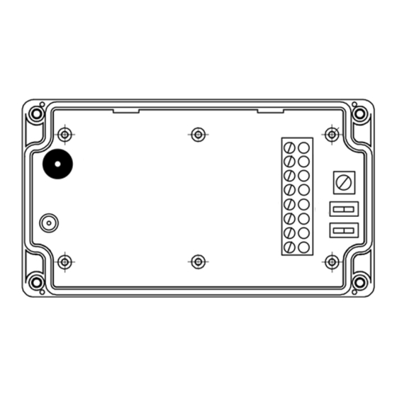
2.0 Receiver Layout
3.0 Cable Requirements
24 AWG minimum, multi-conductor stranded with an overall foil shield, for example Belden 9540 or similar. Per the SIA's Wiegand specification,
maximum cable length is 500 feet (152.4 m).
4.0 Output Formats
Wiegand (industry standard 26-bit Wiegand and custom Wiegand formats).
5.0 Grounding
Shield (drain) continuity must run from the Receiver to the access panel. Shield and reader ground must be tied together at the access panel and
connect then to an earth ground at one point.
6.0 Power
Power required is 12 VDC nominal at 120mA. The Receiver may be powered by the access panel. A linear power supply is recommended for
best operation.
7.0 Mounting
The Receiver may be mounted indoors or outdoors. The base of the enclosure includes a drill template providing mounting provisions to a wall box
(standard North American and European), as well as pre-drilled holes in the four corners allowing mounting to a flat surface. Use supplied #6
mounting screws, or equivalent security screws, for installation.
8.0 Read Range Adjustment
As shipped, the Receiver is set for the maximum read range, which is nominally up to 200 feet (61 m). This may be reduced by adjusting the
range pot in the counter-clockwise direction. Additionally, for optimal read range it is important that the Receiver be mounted as far from
potential interference sources as possible. These sources may include, but are not limited to, large metal obstructions, as well as magnetic fields
and radio transmissions. Note for each installation, read range may vary.
Legend:
a. Antenna Connector
b. Audio Beeper
c. 10-PIN Terminal Block
d. Read Range Adjustment
e. Antenna Switch
f.
Beeper Switch
Advertisement
Table of Contents

Related Manuals for Speco AWRR44


Summary of Contents for Speco AWRR44
- Page 1 Intended for security access control applications, AWRR44’s wireless communications are based upon a secure, digital, anti-playback routine. The four-channel Receiver (Channels A, B, C & D), model AWRR44, allows Transmitter data to be sent over four separate Wiegand outputs. Formatting of the Wiegand output is dependent upon the data encoded on each individual Transmitter.
- Page 2 Operation is subject to the following two conditions: (1) this device may not cause interference, and (2) this device must accept any interference, including interference that may cause unde-sired operation of the device. Speco Technologies reserves the right to change specifications without notice. 800-645-5516 • Fax: 631-957-9142 or 631-957-3880 • specotech.com...
Need help?
Do you have a question about the AWRR44 and is the answer not in the manual?
Questions and answers