Table of Contents
Advertisement
Quick Links
Advertisement
Table of Contents
Troubleshooting

Related Manuals for SealMaster SP 300


Summary of Contents for SealMaster SP 300
- Page 2 ATTENTION: PRE-CHECK ALL LUG NUTS To be sure your new SealMaster SP 300 or SP 575 Machine operates as designed: Pre-Check all lug nuts, and fasteners to be sure they are tight and didn’t loosen during transit. Also, check hoses for damage or leaks to be sure no damage occurred during transit.
- Page 3 SP575 SQUEEGEE AND DUAL/SPRAY SQUEEGEE Owner’s Manual Version 3.0 Issue Date: October 2023 Effective Date: August 2020 Version Date Changes Approval Original Issue 5/20 New Format and Updates 10/20 Plumbing Updates 11/21 Transmission Part No. 1/22 Change Engine Oil – Note 4/22 Added Paint Page 6/22...
-
Page 4: Table Of Contents
Table of Contents CORRESPONDENCE ..............................3 SealMaster® LIMITED WARRANTY ......................... 4 INTRODUCTION ..............................5 SELF-PROPELLED SQUEEGEE AND DUAL / SPRAY SQUEEGEE MACHINE ..............5 SAFETY PRECAUTIONS AND CAUTIONS ........................6 PRECAUTIONS................................6 CAUTIONS .................................. 6 CHECK IT OUT ................................7 KNOW YOUR MACHINE ............................. - Page 5 BEFORE STARTING ENGINE ............................. 26 TO START ENGINE ..............................26 TO OPERATE MACHINE ............................26 FILLING MATERIAL TANK ............................28 OPERATING WATER FOG NOZZLE ........................... 29 SQUEEGEE APPLICATION OF SEALER ........................29 MACHINE PARTS LIST SP575 DUAL / SPRAY ......................30 PARTS LIST ................................
-
Page 7: Sealmaster® Limited Warranty
(30) days from the date failure occurs, and in all cases prior to the expiration of the warranty period of one (1) year. It is the intent of this paragraph to limit SealMaster’s liability solely to the cost of replacement parts, F.O.B. factory, or at the option of SealMaster to repair of the defective part or parts. -
Page 8: Introduction
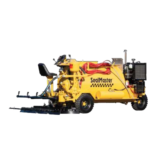
SealMaster offers both self-propelled ride on squeegee machines and self- propelled ride on the dual squeegee and spray seal coating equipment. SealMaster self-propelled seal coating machines are designed to mix and apply pavement sealers with or without sand. SealMaster self-propelled seal coating machines have set the seal coating equipment industry standards for quality, performance, and durability for over 40 years. -
Page 9: Safety Precautions And Cautions
SAFETY PRECAUTIONS AND CAUTIONS PRECAUTIONS • Always wear eye and ear protection, and gloves. • Be aware of all CAUTION - WARNING - DANGER signs on the unit. • Read all Owners Manuals that come with this unit. • Daily check the Engine oil levels. •... -
Page 10: Check It Out
SAFETY PRECAUTIONS AND CAUTIONS CHECK IT OUT Know what protective devices your machine is equipped with and see that each item is securely in place and operating condition. For example: 1. Warning Decals 2. Guards 3. Material hose connections and protective sleeve 4. -
Page 11: Dress For Safety
SAFETY PRECAUTIONS AND CAUTIONS DRESS FOR SAFETY When operating your Squeegee equipment always wear the following: 1. Long pants 2. Long-sleeved shirt 3. Eye protection 4. Work shoes WARNING: MOVING PARTS • Keep hands, feet, hair, and clothing away from all moving parts. •... -
Page 12: Pre-Check All Lug Nuts
ATTENTION: PRE-CHECK ALL LUG NUTS To be sure your new SealMaster SP 300 or SP 575 Machine operates as designed: Pre-Check all lug nuts, and fasteners to be sure they are tight and didn’t loosen during transit. Also, check hoses for damage or leaks to be sure no damage occurred during transit. -
Page 13: Operation Instruction Squeegee Sp575
OPERATION INSTRUCTION SQUEEGEE SP575 BEFORE STARTING ENGINE: 1. Follow the maintenance procedures listed in the engine manual. 2. Check the gas supply. 3. Make sure the control lever #1, located at the left of the steering wheel, is in the neutral position. Along with the 3 levers #7 #8 #9 to the right of the steering wheel. -
Page 14: Filling Material Tank
SQUEEGEE SP575 AGITATOR REAR ASSEMBLY UP CONTROL PANEL CONTROL VALVE AND DOWN ENGINE DISPLAY CONTROL LEVER REAR ASSEMBLY LEFT AND RIGHT WATER TOGGLE SWITCH FILLING MATERIAL TANK: 7. When cutting material in the machine, always place sealer in the tank before adding water. 8. -
Page 15: Operating Water Fog Nozzle
SQUEEGEE SP575 OPERATING WATER FOG NOZZLE: During very hot weather, better adhesion of sealer to blacktop can be obtained by the use of the water fog. Water spray will cool down the asphalt and help mix any dust missed during the cleaning operation. The water tank fill is located under the left sidestep. -
Page 16: Machine Parts List Squeegee Sp575
MACHINE PARTS LIST SQUEEGEE SP575 KUBOTA ENGINE T-HANDLE LATCH STEERING MOTOR & STEERING SHAFT COUPLER BEARING – CONE GAS CAP BEARING - OUTER RACE GAS TANK SPRAY TIP PLUG SHAFT MOTOR – HYD. & WHEEL DRIVE WATER TANK & WATER PUMP-ELECTRIC HYDRAULIC COOLER TIRE &... - Page 17 SQUEEGEE SP575 APPLIES TO: SQUEEGEE SP 575 CONTROL PANEL AGITATOR REAR ASSEMBLY UP CONTROL LEVER ENGINE DISPLAY & KEY CONTROL VALVE AND DOWN REAR ASSEMBLY LEFT AND RIGHT WATER TOGGLE SWITCH PANEL FUSE HOLDER FUSE 25 AMP STEERING WHEEL STEERING COLUMN STEERING CONTROL-HYD.
- Page 18 SQUEEGEE SP575 APPLIES TO: SQUEEGEE SP 575 SEAT COUPLING BEARING PLATE FLANGE BEARING-AGITATOR YOKE CYLINDER LINKAGE ASSEMBLY AGITATION MOTOR FOOT PEDAL ASSEMBLY 3” BUTTERFLY VALVE PARTS LIST ITEM # PART# QTY. DESCRIPTION P70021C008 CYLINDER – HYD. 1-3/4” X 6” P434A004 FLANGE BEARING –...
- Page 19 SQUEEGEE SP575 APPLIES TO: SQUEEGEE SP 575 FILTER TRANSMISSION DIVIDER – PRIORITY FLOW OIL FILTER & TRANSMISSION FILTER HEAD-SMALL FILTER IN LINE PUMP-HYD. FUEL CLEANOUT COVER BAFFLE MOUNT FILTER CAP FILTER FLOW EZY PARTS LIST DIP STICK (INSIDE TANK) ITEM # PART# QTY.
- Page 20 SQUEEGEE SP575 CYLINDER APPLIES TO: SQUEEGEE SP 575 SWIVEL FRAME ASSEMBLY BACKING STRIP NEOPRENE 74” BACKING STRIP BACKING STRIP BOTTOM FRAME ASSEMBLY NEOPRENE 94” NEOPRENE 94” BOX FRAME ASSEMBLY REAR END COMPLETE ASSEMBLY SKID FOOT PARTS LIST ITEM # PART# QTY.
- Page 21 SQUEEGEE SP575 TIRE & WHEEL & SPLIT RIM AND TUBE APPLIES TO: SQUEEGEE SP 575 NORD LOCK-WASHER S.H.C.S. M14-1.5 X 50 NORD LOCK-WASHER, STUD & M14-1.5 LUG NUT WHEEL DRIVE SPLIT RIM NUT & LOCK- WASHER & S.H.C.S. 1/2-20 X 1”...
-
Page 22: Machine Maintenance
SQUEEGEE & DUAL/SPRAY SQUEEGEE APPLIES TO: SP 575 AND SP 575 DUAL MACHINE MAINTENANCE MAINTENANCE SCHEDULE Follow maintenance procedures listed on the engine manual. MAINTAIN WEEK MONTH MONTHS YEAR YEARS CHECK ENGINE OIL LEVELS CHECK HYDRAULIC OIL LEVELS CHECK GASOLINE FUEL LEVELS CHECK COOLANT LEVELS CHECK AIR CLEANER GREASE STEERING SHAFT... -
Page 23: Troubleshooting Guide
SQUEEGEE & DUAL/SPRAY SQUEEGEE APPLIES TO: SP 575 AND SP 575 DUAL TROUBLESHOOTING GUIDE POSSIBLE CAUSES/SOLUTIONS PROBLEM ENGINE OIL SPECIFICATIONS / REFER TO OWNER’S MANUAL ISSUES OPERATING INSTRUCTIONS / REFER TO OWNER’S MANUAL SPARK PLUG WET / DRY OR REPLACE ENGINE DOES NOT START FUEL FILTER CLOGGED / REPLACE FILTER... -
Page 24: Tank Capacity Chart
TANK CAPACITY CHART GALLONS ARE APPROXIMATE AND MAY VARY SLIGHTLY TANK TO TANK MATERIAL DEPTH AND GALLON VOLUME MATERIAL MATERIAL DEPTH GALLONS DEPTH GALLONS 48"x74" 48"x74" INCHES GALLONS INCHES GALLONS... -
Page 25: Kubota Gas Engine Parts List
SQUEEGEE DUAL/SPRAY SQUEEGEE APPLIES TO: SP 575 AND SP 575 DUAL KUBOTA GAS ENGINE PARTS LIST PARTS LIST FOR 1605 GAS ENGINE ITEM # PART# QTY. DESCRIPTION P458A082 KUBOTA WG1605-G-E3 GAS ENGINE P458G028 RADIATOR P458B032 FILTER-OIL P458G001 FILTER-AIR OUTER P458G002 FILTER-AIR INNER P458G034 AIR FILTER COMPLETE... -
Page 26: Wiring Chart Sp575 & Sp575 Dual
WIRING CHART SP575 & SP575 DUAL APPLIES TO: SP 575 AND SP 575 DUAL WIRING FOR ENGINE-IGNITION-HYD. COOLER-FAN RELAY & WATER FAN RELAY SWITCH Red from 20 amp fuse at battery-87 HYDRAULIC OIL COOLER FAN MOTOR Red to red on fan motor-86 Red to relay red Black to black on fan motor-85 Black-butt connect then to black on... -
Page 27: Hydraulic Flow Chart
HYDRAULIC FLOW CHART... -
Page 28: Planetary Gear Hub
SQUEEGEE SP300 & DUAL/SPRAY SQUEEGEE APPLIES TO: SP 575 & SP 575 DUAL PLANETARY GEAR HUB HUB MAINTENANCE... -
Page 29: Operation Instruction Sp575 Dual/Spray
OPERATION INSTRUCTION SP575 DUAL/SPRAY BEFORE STARTING ENGINE: 1. Follow the maintenance procedures listed in the engine manual. 2. Check the gas supply. 3. Make sure the control lever #1, located at the left of the steering wheel, is in the neutral position. Along with the 3 levers #7 #8 #9 to the right of the steering wheel. - Page 30 SQUEEGEE SP575 DUAL/SPRAY IGNITION KEY OFF – RUN - CRANK CONTROL PANEL ENGINE DISPLAY CONTROL LEVER & CABLE CONTROL LEVER & CABLE NEUTRAL POSITION...
-
Page 31: Filling Material Tank
SQUEEGEE SP575 DUAL/SPRAY CONTROL PANEL AGITATOR REAR ASSEMBLY UP REAR ASSEMBLY ENGINE DISPLAY CONTROL VALVE AND DOWN LEFT AND RIGHT CONTROL LEVER & CABLE WATER TOGGLE SWITCH FILLING MATERIAL TANK: 7. When cutting material in the machine, always place sealer in the tank before adding water. -
Page 32: Operating Water Fog Nozzle
SQUEEGEE SP575 DUAL/SPRAY OPERATING WATER FOG NOZZLE: During very hot weather, better adhesion of sealer to blacktop can be obtained by the use of the water fog. Water spray will cool down the asphalt and help mix any dust missed during the cleaning operation. -
Page 33: Machine Parts List Sp575 Dual / Spray
MACHINE PARTS LIST SP575 DUAL / SPRAY KUBOTA ENGINE T-HANDLE LATCH STEERING MOTOR & STEERING SHAFT COUPLER BEARING – CONE GAS CAP BEARING - OUTER RACE GAS TANK SPRAY TIP PLUG SHAFT MOTOR – HYD. & WHEEL DRIVE WATER TANK & WATER PUMP-ELECTRIC TIRE &... - Page 34 SQUEEGEE SP575 DUAL/SPRAY APPLIES TO: SP 575 DUAL/SPRAY CONTROL PANEL AGITATOR REAR ASSEMBLY UP REAR ASSEMBLY ENGINE DISPLAY & KEY CONTROL VALVE AND DOWN LEFT AND RIGHT CONTROL LEVER & CABLE SPRAY WAND ASSEMBLY SPRAY TIP MANIFOLD 3/4 BALL VALVE FLOW CONTROL 3/4”...
- Page 35 SQUEEGEE SP575 DUAL/SPRAY SEAT SURGE TANK APPLIES TO: SP 575 DUAL/SPRAY LINKAGE ASSEMBLY CYLINDER BEARING PLATE & COUPLING FLANGE BEARING-AGITATOR AGITATION MOTOR STRAINER BASKET LID GASKET YOKE ASSEMBLY FOOT PEDAL ASSEMBLY STRAINER 3” BUTTERFLY VALVE BASKET COMPLETE ASSEMBLY PARTS LIST ITEM # PART# QTY.
- Page 36 SQUEEGEE SP575 DUAL/SPRAY APPLIES TO: SP 575 DUAL/SPRAY BALL VALVE 2” BALL VALVE 2” BALL VALVE 2” BALL VALVE 3/4” BALL VALVE 2” BALL VALVE 2” BALL VALVE 3/4” CHECK VALVE 3/4” PARTS LIST ITEM # PART# QTY. DESCRIPTION P397A002 2”...
- Page 37 SQUEEGEE SP575 DUAL/SPRAY APPLIES TO: SP 575 DUAL/SPRAY FILTER TRANSMISSION OIL FILTER & TRANSMISSION FILTER HEAD-SMALL PUMP-HYD. FILTER IN LINE FUEL CLEANOUT COVER BAFFLE MOUNT DIP STICK FILTER FLOW EZY (INSIDE TANK) PARTS LIST FILTER CAP ITEM # PART# QTY. DESCRIPTION P408A003 FILTER –...
- Page 38 SQUEEGEE SP575 DUAL/SPRAY APPLIES TO: SP 575 DUAL/SPRAY SPRAY TIP 80/70 1/2" BALL VALVE SPRAY-BAR ASSEMBLY CYLINDER SKID FOOT SWIVEL FRAME ASSEMBLY BACKING STRIP NEOPRENE 74” BACKING STRIP BACKING STRIP NEOPRENE 94” BOTTOM FRAME ASSEMBLY BOX FRAME ASSEMBLY NEOPRENE 94” REAR END COMPLETE PARTS LIST...
- Page 39 SQUEEGEE SP575 DUAL/SPRAY APPLIES TO: SP 575 DUAL/SPRAY NORD LOCK-WASHER & NORD LOCK-WASHER STUD- M14 X1.5 DOUBLE END S.H.C.S. M14-1.5 X 50 & LUG NUT M14-1.5 SPLIT RIM NUT & LOCK- WASHER & S.H.C.S. 1/2-20 X 1” WHEEL DRIVE HUB & TIRE &...
- Page 40 SQUEEGEE SP575 DUAL/SPRAY APPLIES TO: SP 575 DUAL/SPRAY SAND PUMPER II PUMP TOGGLE SWITCH COMPLETE ASSEMBLY PUMP SPEED CONTROL PUMP PRESSURE CONTROL PUMP PRESSURE GAUGE SAND PUMPER II CYLINDER ASSEMBLY CARTRIDGE VALVE SOLENOID 12V COIL PARTS LIST ITEM # PART# QTY.
-
Page 41: Sandpumper Ii
SQUEEGEE SP575 DUAL/SPRAY SANDPUMPER II SANDPUMPER II... -
Page 42: Parts List
SQUEEGEE SP575 DUAL/SPRAY APPLIES TO: SP 575 DUAL PARTS LIST ITEM # PART# QTY. DESCRIPTION P966A078 SWITCH MOUNT COVER P966A079 MOUNTING PLATE - SWITCH P442A003 SNAP SWITCH P966A080 LEVER P966A081 SHIFTING ARM P966A082 CHAMBER DIAPHRAGM P966A083 GASKET - CHAMBER DIAPHRAGM P966A084 ELBOW - CHAMBER DIAPHRAGM P966A085... - Page 43 SQUEEGEE SP575 DUAL/SPRAY APPLIES TO: SP 575 DUAL PARTS LIST ITEM # PART# QTY. DESCRIPTION P1033A001 SET COLLAR 3/8” P1015A010 SET SCREW 1/4”-20 X 1/2” P1015A004 SET SCREW 1/4”-20 X 1/4” P966A095 COVER PLATE BRACKET P966A091 FOOT MOUNT P1010A001 REDUCER BUSHING 3/8” TO 1/4" P560A022 HYDRAULIC TEE 3/8”...
-
Page 44: Operation Instruction Sandpumper Ii
OPERATION INSTRUCTION SANDPUMPER II GENERAL OPERATION & SERVICE INSTRUCTIONS - REPAIR: 1. The SandPumper II diaphragms are operated internally on a double rod cylinder shaft. A stroke directional limit switch is mounted between diaphragms and sends a signal to the solenoid-operated manifold to indicate the end of stroke and the beginning of a reverse stroke. -
Page 45: Troubleshooting Guide
OPERATION INSTRUCTION SANDPUMPER II TROUBLESHOOTING GUIDE POSSIBLE CAUSES/SOLUTIONS PROBLEM BASKET STRAINER AND/OR LINES CLOGGED / CLEAN STRAINER AND/OR LINES TOGGLE SWITCH HAS NO POWER / CHECK FUSE OR WIRING SOLENOID COIL HAS NO POWER / CHECK ALL SWITCHES FOR OPEN CIRCUIT SOLENOID COIL HAS POWER WIL NOT ACTIVATE / REPLACE SOLENOID COIL PUMP STOP COLLARS HAVE MOVED/ REPOSITION COLLARS OVER MARKS-RETIGHTEN... -
Page 46: Disassembly-Assembly Diaphragms Sandpumper Ii
DISASSEMBLY-ASSEMBLY DIAPHRAGMS SANDPUMPER II 1. CHANGING THE DIAPHRAGMS: a. Measure the gap between flanges. b. Remove the cover from the top of the pump. c. Start engine-turn on toggle switch-open the pump speed control-let the actuator rod shift fully to the side of the pump you will be servicing first-close the pump speed control shut off the toggle switch and the engine. -
Page 47: Changing The Diaphragms: - Actuator Rod
plate and slide it onto the bolt coming through the diaphragm, mating the groove to the diaphragm bead. Thread the bolt into the cylinder rod, when snug you can adjust all the diaphragm beads to fit the grooves in the support plates and other flanges. -
Page 48: Check Ball Assembly Sandpumper Ii
CHECK BALL ASSEMBLY SANDPUMPER II 1. SERVICING THE CHECK BALLS: a. Loosen the hose clamp on the bypass hose. b. Where the plumbing connects to the pump is a flange and gasket #109 with 2 bolts-remove these and lift the discharge piping out of your way. -
Page 49: Squeegee Sp575 Dual/Spray
SQUEEGEE SP575 DUAL/SPRAY FILLING THE TANK FROM ANOTHER CONTAINER: 1. Follow the maintenance procedures listed in the engine manual. 2. Connect a suction hose to pump in valve #83 and your drum or tank. Open the valve. 3. Open recirculation valve #79. 4. -
Page 50: Application - Spray Wand
SQUEEGEE SP575 DUAL/SPRAY APPLICATION – SPRAY WAND: 1. Start with thoroughly mixed material. 2. Remove the basket strainer lid #75 and check the strainer basket #73, clean if needed. 3. Open main feed valve #81. Turn on pump toggle switch #10. Open the pump speed control valve #90 about three turns. -
Page 51: Application - Spray Bar
SQUEEGEE SP575 DUAL/SPRAY APPLICATION – SPRAY BAR: 1. Perform steps 1-4 from above. 2. Open all 1/2” ball valves #86 on the spray bar #85. 3. Start the machine in motion and slowly open spray bar valve #77. Completely open the valve as you increase your forward motion speed. You may need to increase the pump speed control valve #90 and pressure control knob #89. - Page 52 SQUEEGEE SP575 DUAL/SPRAY RECIRCULATION VALVE 2” SPRAY BAR PUMP OUT VALVE 2” VALVE 2” WAND HOSE VALVE 3/4” MAIN FEED VALVE 2” PUMP IN VALVE 2” BASKET STRAINER ASSEMBLY LID GASKET STRAINER BASKET CHECK VALVE WATER FLUSH VALVE 3/4” 3/4”...
- Page 53 SQUEEGEE SP575 DUAL/SPRAY PUMP TOGGLE SWITCH SANDPUMPER II PUMP PRESSURE GAUGE COMPLETE ASSEMBLY PUMP SPEED CONTROL PUMP PRESSURE CONTROL AGITATOR CONTROL VALVE SPEED CONTROL 1/2" BALL VALVE SPRAY-BAR ASSEMBLY AGITATION MOTOR WITH SPEED CONTROL...
-
Page 54: Hydraulic Spray Bar Optional
SQUEEGEE SP575 DUAL/SPRAY APPLIES TO: SP 575 DUAL HYDRAULIC SPRAY BAR OPTIONAL HYDRAULIC CYLINDER ASSEMBLY CARTRIDGE VALVE SOLENOID 12V COIL CYLINDER CUSTOM CUT 3/4" BALL VALVE VALVE HANDLE SPRAY BAR ASSEMBLY COMPLETE SPRAY TIP 80/70 SPRAY BAR TOGGLE SWITCH FUSE HOLDER FUSE 15 AMP PARTS LIST ITEM #... -
Page 55: How To Winterize Your Equipment
SQUEEGEE SP575 & SP575 DUAL/SPRAY HOW TO WINTERIZE YOUR EQUIPMENT 1. If the machine has been in use, add water to the tank and let it agitate at a high speed for 30 minutes. Pump this water through the spray wand. -
Page 56: Recommended Spare Parts List
SQUEEGEE SP575 & SP575 DUAL/SPRAY RECOMMENDED SPARE PARTS LIST LIST FOR: GAS ENGINES PART# QTY. DESCRIPTION P458B203 FILTER – GAS IN LINE FUEL P908A003 FILTER – OIL RETURN LINE P908A007 FILTER – TRANSMISSION FLUID P408A003 FILTER – OIL FLOW EZY P458B032 FILTER –... -
Page 57: Maintenance And Storage
MAINTENANCE AND STORAGE MAINTENANCE During the lubrication stop, inspect all operating parts. Should any damage or excessive wear be evident, replace parts immediately. Straighten any parts as soon as possible. Clean and re-paint all exposed parts using touch-up kit P3020B034 yellow paint or touch-up kit P3020B033 black...
Need help?
Do you have a question about the SP 300 and is the answer not in the manual?
Questions and answers