Advertisement
Quick Links
Owner's Manual & Safety Instructions
Save This Manual
operating, inspection, maintenance and cleaning procedures. Write the product's serial number in the
back of the manual near the assembly diagram (or month and year of purchase if product has no number).
Keep this manual and the receipt in a safe and dry place for future reference.
HIGH PERFORMANCE
email our technical support at: productsupport@harborfreight.com
When unpacking, make sure that the product is intact
and undamaged. If any parts are missing or broken,
please call 1-888-866-5797 as soon as possible.
©
Copyright
2019 by Harbor Freight Tools
No portion of this manual or any artwork contained herein may be reproduced in
any shape or form without the express written consent of Harbor Freight Tools.
Diagrams within this manual may not be drawn proportionally. Due to continuing
improvements, actual product may differ slightly from the product described herein.
Tools required for assembly and service may not be included.
Keep this manual for the safety warnings and precautions, assembly,
6 GALLON
OIL FREE - PORTABLE
Visit our website at: http://www.harborfreight.com
®
. All rights reserved.
SERIES
AIR COMPRESSOR
Read this material before using this product.
Failure to do so can result in serious injury.
SAVE THIS MANUAL.
23d
56829
Advertisement

Subscribe to Our Youtube Channel
Related Manuals for Fortress Technologies HIGH PERFORMANCE Series


Summary of Contents for Fortress Technologies HIGH PERFORMANCE Series
- Page 1 Owner’s Manual & Safety Instructions Save This Manual Keep this manual for the safety warnings and precautions, assembly, operating, inspection, maintenance and cleaning procedures. Write the product’s serial number in the back of the manual near the assembly diagram (or month and year of purchase if product has no number). Keep this manual and the receipt in a safe and dry place for future reference.
- Page 2 table of contents Safety ............2 Maintenance ..........11 Installation ..........6 Parts List and Diagram ......14 Specifications ..........6 Warranty ............ 16 Operation ............ 9 WarninG SyMBOlS anD DeFinitiOnS This is the safety alert symbol. It is used to alert you to potential personal injury hazards.
- Page 3 iMpOrtant SaFety inFOrMatiOn General Safety Warnings WarninG read all safety warnings and instructions. Failure to follow the warnings and instructions may result in electric shock, fire and/or serious injury. Save all warnings and instructions for future reference. The warnings, precautions, and instructions discussed in this instruction manual cannot cover all possible conditions and situations that may occur.
- Page 4 air compressor Safety Warnings 1. risk of fire or explosion - do not spray 14. USE OF AN EXTENSION CORD IS NOT flammable liquid in a confined area or towards a RECOMMENDED. If you choose to use an hot surface. Spray area must be well-ventilated. extension cord, use the following guidelines: Do not smoke while spraying or spray where taBle a: recOMMenDeD MiniMUM Wire...
- Page 5 Grounding tO preVent electric SHOcK anD DeatH FrOM incOrrect GrOUnDinG Wire cOnnectiOn: check with a qualified electrician if you are in doubt as to whether the outlet is properly grounded. Do not modify the power cord plug provided with the compressor. never remove the grounding prong from the plug.
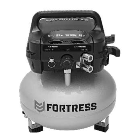
- Page 6 Specifications Electrical Rating 120VAC / 60Hz / 12A Air Outlet Size 1/4″ - 18 NPT Air Hose Plug Style Automotive (M) or Industrial (A) Shut-off 175 PSI Air Pressure Restart 145 PSI Air Tank Capacity 6 Gallons Air Flow Capacity 3.0 SCFM @ 90 PSI Sound Level 81 dBA @ 3'...
- Page 7 Functions tank regulator Outlet Gauge Gauge power Safety Switch Valve Outlets Drain Valve Item 56829 For technical questions, please call 1-888-866-5797. Page 7...
- Page 8 Breaking in the air compressor 1. Turn Power Switch OFF 3. Fully open Drain Valve. and unplug Power Cord. 4. Plug in Power Cord. 5. Turn Power Switch ON. 2. Pull out the Regulator 6. Let unit run for 15 minutes. Air will expel freely and fully open it, then through the Drain Valve.
- Page 9 Operating instructions read the entire iMpOrtant SaFety inFOrMatiOn section at the beginning of this manual including all text under subheadings therein before set up or use of this product. General Operation 1. Close Drain Valve. note: As long as the Power Switch is ON, the operation of the Air Compressor is automatic, controlled by an internal pressure switch.
- Page 10 emergency Depressurization If it is necessary to quickly depressurize the Air Compressor, turn the Power Switch OFF. Then, pull on the ring on the Safety Valve to quickly release stored air pressure. automatic Shut off System 1. If the Air Compressor automatically shuts off 2.
- Page 11 Maintenance and Servicing procedures not specifically explained in this manual must be performed only by a qualified technician. tO preVent SeriOUS inJUry FrOM acciDental OperatiOn: turn the power Switch “OFF” and unplug the air compressor from its electrical outlet before performing any inspection, maintenance, or cleaning procedures. tO preVent SeriOUS inJUry FrOM air cOMpreSSOr FailUre: Do not use damaged equipment.
- Page 12 troubleshooting problem possible causes likely Solutions Compressor does 1. Tank(s) already pressurized. 1. No problem. Compressor will start when needed. not start or restart 2. Power cord not plugged in properly. 2. Check that cord is plugged in securely. 3. Incorrect power supply. 3.
- Page 13 pleaSe reaD tHe FOllOWinG careFUlly THE MANUFACTURER AND/OR DISTRIBUTOR HAS PROVIDED THE PARTS LIST AND ASSEMBLY DIAGRAM IN THIS MANUAL AS A REFERENCE TOOL ONLY. NEITHER THE MANUFACTURER OR DISTRIBUTOR MAKES ANY REPRESENTATION OR WARRANTY OF ANY KIND TO THE BUYER THAT HE OR SHE IS QUALIFIED TO MAKE ANY REPAIRS TO THE PRODUCT, OR THAT HE OR SHE IS QUALIFIED TO REPLACE ANY PARTS OF THE PRODUCT.
- Page 14 parts list and Diagram parts list part Description part Description Handle O-Ring Cross Tapping Screw Plug Hex Tapping Screw Safety Valve Upper Housing Regulator Hex Combination Screw Quick Connect Pump Assembly Pressure Regulating Valve Assembly Cross Screw & Flat Gasket Assembly Tank Pressure Gauge Support Cushions Outlet Pressure Gauge...
- Page 15 assembly Diagram Item 56829 For technical questions, please call 1-888-866-5797. Page 15...
- Page 16 limited 90 Day Warranty Harbor Freight Tools Co. makes every effort to assure that its products meet high quality and durability standards, and warrants to the original purchaser that this product is free from defects in materials and workmanship for the period of 90 days from the date of purchase.
Need help?
Do you have a question about the HIGH PERFORMANCE Series and is the answer not in the manual?
Questions and answers
I have a Fortress FT6175 and can not find replacement parts. I've attached a picture. It looks like the electric motor but all we need are the plastic ends that the brushes go into as they will not keep pressure on them and also the fan has a broken blade.