Advertisement
CONNECTING THE JUMP STARTER

A SPARK NEAR THE BATTERY MAY CAUSE A BATTERY EXPLOSION. TO REDUCE THE RISK OF A SPARK NEAR THE BATTERY:
- Attach the output cables to the battery and chassis as indicated below. Never allow the output clips to touch each other.
- Position the DC cables to reduce the risk of damage by the hood, door and moving or hot engine parts.
NOTE: If it is necessary to close the hood during the jump starting process, ensure that the hood does not touch the metal part of the battery clips or cut the insulation of the cables. - Stay clear of fan blades, belts, pulleys and other parts that can cause injury.
- Check the polarity of the battery posts. The POSITIVE (POS, P, +) battery post usually has a larger diameter than the NEGATIVE (NEG, N, -) post.
- Determine which post of the battery is grounded (connected) to the chassis. If the negative post is grounded to the chassis (as in most vehicles), see step 6. If the positive post is grounded to the chassis, see step 7.
- For a negative-grounded vehicle, connect the POSITIVE (RED) clip from the jump starter to the POSITIVE (POS, P, +) ungrounded post of the battery. Connect the NEGATIVE (BLACK) clip to the vehicle chassis or engine block away from the battery. Do not connect the clip to the carburetor, fuel lines or sheet-metal body parts. Connect to a heavy gauge metal part of the frame or engine block.
- For a positive-grounded vehicle, connect the NEGATIVE (BLACK) clip from the jump starter to the NEGATIVE (NEG, N, -) ungrounded post of the battery. Connect the POSITIVE (RED) clip to the vehicle chassis or engine block away from the battery. Do not connect the clip to the carburetor, fuel lines or sheet-metal body parts. Connect to a heavy gauge metal part of the frame or engine block.
- When disconnecting the jump starter, turn all switches to off (if applicable), remove the clip from the vehicle chassis, then remove the clip from the battery terminal.
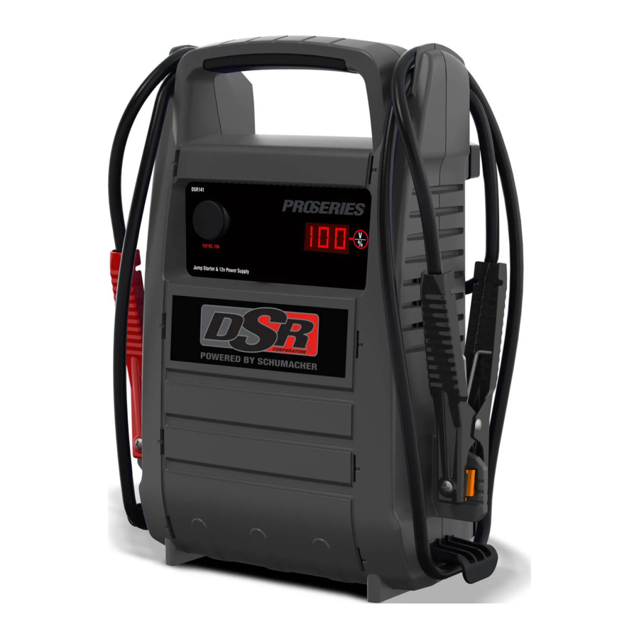
FEATURES
Jump Starter

- Battery clamps
- 12V DC socket
- Digital display
- Display button
Charger
- Charging status LED
- Bad Battery LED
- Power LED
DIGITAL DISPLAY
The digital display can be used to indicate the percent of charge or the voltage and percentage of the jump starter's internal battery.
- To check the voltage level of the jump starter's internal battery, make sure the clips are attached to their plastic storage holders and not touching each other, and then press the Display button on the front of the jump starter. The display will indicate the battery's voltage. Press the Display button a second time to show the battery's percentage. Charge the internal battery if the display shows it is under 100%.
- While charging, press the Display button to check the internal battery's charging status. The digital display will show the battery's percent of charge. A fully charged battery will read 100%.
NOTE: The internal battery's percent of charge is most accurate when the jump starter has been disconnected from all devices and charging sources for a few hours. - To check the voltage level of the vehicle's battery, connect the clips to the vehicle's battery and then press the Display button. The display will indicate the combined voltage of the jump starter's internal battery and the vehicle battery.
- To check the connected vehicle's battery status, press the Display button a second time. The digital display will show the combined percentage of the jump starter's internal battery and the vehicle battery.
CHARGER LED INDICATORS
POWER (green) LED lit: The charger is connected to AC power.
CHARGING STATUS LED (green) pulsing slowly: The charger is charging the jump starter's internal battery, or the battery is fully charged and the charger is in Maintain mode.
CHARGING STATUS LED (yellow/orange) flashing rapidly: The charger has detected a problem with the battery. See Troubleshooting for more information.
BAD BATTERY (red) LED lit: The charger has detected a problem with the battery. SeeTroubleshooting for more information.
CHARGING THE INTERNAL BATTERY OF THE JUMP STARTER

CHARGE IMMEDIATELY AFTER PURCHASE, AFTER EACH USE AND EVERY 30 DAYS, TO KEEP THE UNIT'S INTERNAL BATTERY FULLY CHARGED AND PROLONG BATTERY LIFE.
To check the internal battery's charge status, press the Display button twice. The digital display will show the battery's percent of charge. A fully charged battery will read 100%. Charge the internal battery if the display shows it is under 100%. Complete charging may take up to 48 hours.
GROUNDING AND AC POWER CORD CONNECTIONS
Only use the charger that was included with the jump starter to charge the internal battery of the jump starter. Using a different charger could result in personal injury or property damage.
RISK OF ELECTRIC SHOCK OR FIRE.
This battery charger is for use on a nominal 120V circuit. The plug must be plugged into an outlet that is properly installed in accordance with all local codes and ordinances. The plug pins must fit the receptacle (outlet). Do not use with an ungrounded system.

Never alter the AC cord or plug provided – if it does not fit the outlet, have a proper outlet installed by a qualified electrician. An improper connection can result in a risk of an electric shock or electrocution.
An extension cord should not be used unless absolutely necessary. Use of an improper extension cord could result in a risk of fire and electric shock. If an extension cord must be used, make sure:
- The pins on the plug of the extension cord are the same number, size and shape as those of the plug on the charger.
- The extension cord is properly wired and in good electrical condition.
- The wire size is large enough for the AC ampere rating of the charger, as specified:
| Length of cord (feet) | 25 | 50 | 100 | 150 |
| AWG* size of cord | 18 | 18 | 18 | 16 |
*AWG-American Wire Gauge
CHARGING THE JUMP STARTER WITH INCLUDED CHARGER
- Make sure the charger and jump starter are placed on a dry, nonflammable surface. To charge the jump starter, plug the charger into the charging port on the back of the jump starter.
- Confirm the AC outlet voltage matches the input voltage of the charger.
- Connect the charger to the AC wall outlet and confirm that the green Power LED on the charger turns on.
- Check that the green Charging Status LED on the charger is pulsing slowly, to indicate that charge process has started. To see the status of the charge, check the percentage shown on the jump starter display.
- When the jump starter display shows 100 (%), the internal battery is fully charged and the jump starter is ready to use. Complete charging may take up to 24 hours.
NOTE: The green Charging Status LED will remain pulsing after the display shows 100%, as the charger automatically goes into Maintain mode and maintains the battery at full charge without damaging it. - After the charge is complete, disconnect the charger from the AC outlet, then disconnect the charger from jump starter.
CHARGER MODES
Automatic charging mode
When an automatic charge is performed, the charger switches to maintain mode automatically after the battery is charged.
Aborted Charge
If charging cannot be completed normally, charging will abort. When charging aborts, the charger's output is shut off. The Bad Battery (red) LED will light. Do not continue attempting to charge the battery. Check the battery and replace, if necessary.
Desulfation Mode
Desulfation could take 8 to 10 hours. If desulfation fails, charging will abort. The red Bad Battery LED will light and the yellow/orange Charging Status LED will flash.
Completion of Charge
When the internal battery is fully charged, the jump starter's display will show "100".
Maintain Mode (Float Mode Monitoring)
When the internal battery is fully charged and the jump starter display shows "100", the charger has started maintain mode. In this mode, the charger keeps the battery fully charged by delivering a small current when necessary. If the charger has to provide its maximum maintain current for a continuous 12 hour period, it will go into abort mode (see Aborted Charge). This is usually an indication of a bad battery; have the jump starter checked.
CHARGING THE INTERNAL BATTERY WHILE DRIVING
You may also charge the internal battery while driving, using a male-to-male charger cable (part number 94500109 – sold separately).
WHEN USING A 12V PORT CHARGING CABLE, DO NOT CHARGE THE INTERNAL BATTERY FOR MORE THAN 30 MINUTES OR LEAVE THE BATTERY UNATTENDED. IT COULD EXPLODE, CAUSING PROPERTY DAMAGE OR PERSONAL INJURY.
- Make sure the car is running.
- Insert one end of the accessory cable into the 12V DC power outlet.
- Insert the other end of the accessory cable into the vehicle's accessory outlet (lighter socket).
NOTE: Using this method to charge the battery overrides the maintain mode and the battery can be overcharged. - Monitor the progress of the charge by pressing the Display button twice. Do not leave the battery unattended or it could explode, causing property damage and personal injury. When the battery is fully charged, disconnect the accessory cable from the jump starter, and then from the lighter socket of the vehicle.
NOTE: Completely disconnect the charger cable when the engine is not running.
JUMP STARTING A VEHICLE ENGINE
Using the jump starter without a battery installed in the vehicle will damage the vehicle's electrical system.
Do not use the jump starter while charging its internal battery.
- Turn the vehicle's ignition OFF before making cable connections.
- Connect the jump starter to the battery, following the precautions listed in CONNECTING THE JUMP STARTER.
![]()
RISK OF EXPLOSION.
If you have connected the clips backward, an audio alarm will sound. Reverse the connections and the audio alarm will stop. The clips are now powered. - Crank the engine. If the engine does not start within 3-8 seconds, stop cranking and wait at least 1 minute before attempting to start the vehicle again. (This permits the battery to cool down.)
- After the engine starts, disconnect the black clip (-), then the red clip (+) in that order, and clip them back onto the jump starter storage holders.
- Recharge the jump starter as soon as possible after use.
NOTE: If the jump starter is connected to a battery for more than five minutes, four beeps will sound. This is a reminder to turn the jump starter off and/or disconnect it from the vehicle's battery when not in use.
RISK OF EXPLOSION.
To prevent sparking, NEVER allow the clips to touch together or to contact the same piece of metal.
Never attempt to jump start a frozen battery.
POWERING A 12V DC DEVICE
The jump starter is a power source for all 12V DC accessories that are equipped with a 12V accessory plug. Use it for power outages and fishing or camping trips. Estimated usage time is listed in the following chart.
- Make sure the device to be powered is OFF before inserting a 12V DC accessory plug into the 12V DC socket.
- Ensure the battery clips are securely clipped on the storage holders.
- Open the protective cover of the 12V DC power outlet on the front of the jump starter.
- Plug the 12V DC device into the 12V DC power outlet, and turn on the 12V DC device (if required).
- If the 12V DC device draws more than 15A or has a short circuit, the internal circuit breaker of the jump starter will trip and disconnect the power to the device. Disconnect the 12V DC device. The breaker will automatically reset a short time after an overload is disconnected.
- Recharge immediately after unplugging the 12V DC device.
NOTE: The DC power outlet is wired directly to the internal battery. Extended operation of a 12V DC device may result in excessive battery drain.
12V DC ESTIMATED RUN-TIMES
| APPLIANCE TYPE | EST. WATTAGE | EST. RUN TIME |
| Cell phone, fluorescent light | 4 watts | 66 hrs. |
| Radio, fan, depth finder | 9 watts | 29.3 hrs. |
| Camcorder | 15 watts | 17.6 hrs. |
| Electric tool | 24 watts | 11 hrs. |
| Electric cooler | 48 watts | 5.5 hrs. |
| Car vacuum, air compressor | 80 watts | 3.3 hrs. |
NOTE: Actual time may vary. Times are based on the internal battery being fully charged.
MAINTENANCE INSTRUCTIONS
- After use and before performing maintenance, unplug and disconnect the jump starter.
- Use a dry cloth to wipe all battery corrosion and other dirt or oil from the battery clips, cords and the jump starter case.
- Ensure that all of the jump starter components are in place and in good working condition.
- All servicing should be performed by qualified service personnel.
MOVING AND STORAGE INSTRUCTIONS
Jump Starter
| PROBLEM | POSSIBLE CAUSE | SOLUTION |
| The jump starter won't jump start my car. | Clamps are not making a good connection to the battery. | Check for poor connection to battery and frame. Make sure connection points are clean. |
| The jump starter's battery is not charged. | Check the battery charge status by pressing the Display button on the front of the unit. The display will show the percentage of charge. | |
| The vehicle's battery is defective. | Have the battery checked. | |
| The jump starter won't power my 12V device. | The 12V device is not turned on. | Turn on the 12V device. |
| The jump starter's battery is not charged. | Check the battery charge status by pressing the Display button on the front of the unit. The display will show the percentage of charge. | |
| The 12V device draws more than 15A or has a short circuit. | Disconnect the 12V device. The internal breaker will automatically reset after a minute or two. Try using the 12V device again. | |
| The battery in the jump starter won't hold a charge. The jump starter's alarm is on. Connections are reversed. | The battery is bad (will not accept a charge). | Replace the battery. Disconnect the jump starter and reverse the clamps. |
Charger
| PROBLEM | REASON | SOLUTION |
| The green Power LED does not light when charger is properly connected. | AC outlet is dead. | Check for open fuse or circuit breaker supplying AC outlet. |
| Poor electrical connection. | Check power cord and extension cord for a loose fitting plug. | |
| The red Bad Battery LED is lit. | The battery is sulfated. | The charger is in desulfation mode. Continue charging for several hours. If not successful, have the battery checked. |
| Lack of progress is detected and battery voltage is below 14.2V. | The battery may be overheated. If so, allow the battery to cool. The battery may be too large or have a short circuit. Have battery checked or replaced. | |
| The battery's initial voltage is below 12.2V and the total input is less than 1.5 Ah. | The battery capacity is too low, or the battery is too old. Have it checked or replaced. | |
| The battery voltage drops below 12.2V during Maintain Mode. | The battery won't hold a charge. May be caused by a drain on the battery or the battery could be bad. Make sure there are no loads on the battery. If there are remove them. If there are none, have the battery checked or replaced. | |
| The red Bad Battery LED is lit and the yellow/orange Charging Status LED is flashing rapidly. | The battery voltage is still below 10V after 2 hours of charging. (or) In maintain mode, the output current is more than 1.5A for 12 hours. | The battery may be defective. Make sure there are no loads on the battery. If there are, remove them. If there are none, have the battery checked or replaced. |
| Desulfation was unsuccessful. | The battery may be defective. Have battery checked or replaced. |
BEFORE RETURNING FOR REPAIRS
For information about troubleshooting, contact customer service for assistance: services@schumacherelectric.com
www.batterychargers.com
or call 1-800-621-5485
For REPAIR OR RETURN, contact Customer Service at 1-800-621-5485. DO NOT SHIP UNIT until you receive a RETURN MERCHANDISE AUTHORIZATION (RMA) number from Customer Service at Schumacher Electric Corporation.
REPLACEMENT PARTS/ACCESSORIES
Male-to-male accessory cable: 94500109
Charger: 2299003063Z
Replacement battery: 5799000010Z
Documents / Resources
References
Download manual
Here you can download full pdf version of manual, it may contain additional safety instructions, warranty information, FCC rules, etc.
Download Schumacher DSR141 - ProSeries 12V 2000 Peak Amp Jump Starter and DC Power Source Manual
Advertisement


Need help?
Do you have a question about the DSR141 and is the answer not in the manual?
Questions and answers