Table of Contents
Advertisement
Quick Links
Advertisement
Table of Contents

Related Manuals for CabCAM QM7127R


Summary of Contents for CabCAM QM7127R
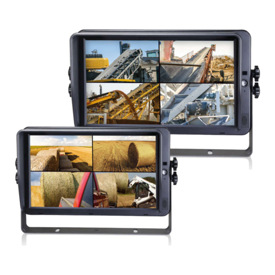
- Page 1 Operating Instructions 7"/10.1" HD Digital LCD Color Monitor Please read this manual before you use the product. The product may be different from the described in the manual depending on renewal or upgrade of Software version and performance and it can be altered without notice.
-
Page 2: Table Of Contents
Contents 1.Precautions......................1 2.Features and Specifications................3 3. Accessories...................... 4 4. Parts Identification...................5 5. Connections..................... 6 6. Menu Operation & Functional Specification..........7 6.1 IR Remote Control.................. 7 6.2 Menu Operation..................8 6.2.1 Desktop................... 8 6.2.2 Home Menu..................9 6.2.3 Volume.....................9 6.2.4 Mode....................10 6.2.5 Setting................... -
Page 3: Precautions
1. Precautions ● Storage and Keeping Do not expose the monitor to excessive heat or coldness. Storage temperature is -30~+80℃; Operating temperature is -20~+70 ℃; Humidity is Rh90%. Never use this device near a bathtub, wash basin, kitchen, damp basement, swimming pool or similar places. - Page 4 ● Maintenance 1. Remove all the cable connections from the monitor before cleaning the device. 2. Use a mild household detergent and clean the unit with a slightly damp, soft cloth. 3. Never use strong solvents such as thinner or benzine, as they might damage the finish of the device.
-
Page 5: Features And Specifications
2.Features and Specifications 10.1”/7’’ HD quad-view monitor with LVDS interface, support input up to resolution at 1920 *1080. Support 4 channel cameras in PAL / NTSC / HDA / HDT / HDC (720p/1080p). Image can be set to horizontally flipped, vertically flipped, normal and zoom Image. -
Page 6: Accessories
3. Accessories U-Support Bracket Center Mount Bracket Power cable Sun Shield Angle Adjustment Screws IR Remote control Power cable Special Notice Accessory supply may be different for different application. -
Page 7: Parts Identification
4. Parts Identification Remote control sensor Power Switch / Power indicator Light lever sensor Loudspeaker Digital Color LCD screen, touch screen Mounting bracket installation... -
Page 8: Connections
5. Connections ①: Red: A: Camera1 White 4PIN male ②: Black: GND B: Camera2 Blue 4PIN male ③: White: Camera1 trigger C: Camera3 Green 4PIN male ④: Blue: Camera2 trigger D: Camera4 Brown 4PIN male ⑤: Green: Camera3 trigger E: Black 5PIN male ⑥: Brown: Camera4 trigger F: Black 5PIN Female: ⑦: Yellow: Split trigger... -
Page 9: Menu Operation &Functional Specification
6. Menu Operation &Functional Specification 6.1 IR Remote Control Standby mode enter or quit Mute or unmute Call home menu or return to Move up the menu cursor previous menu Move up the menu cursor or Move up the menu cursor or increase volume decrease volume Confirmation button... -
Page 10: Menu Operation
6.2 Menu Operation 6.2.1 Desktop Pic. 6.2.1-1 ●Touch anywhere in white lined section to call home menu. Pic. 6.2.1-2 ●When signal source is selected to be cameras, image display mode can be swi tched by sliding to left / right on screen in the order: LEFT->RIGHT->FRONT->BA CK->DUAL->TRIPLE->TREFOIL->Y-SPLIT->H SPLIT->QUAD->LEFT. -
Page 11: Home Menu
6.2.2 Home Menu Pic.6.2.2 ●Touch the icons to enter the menu or touch the area out of the white lined to exit. 6.2.3 Volume Pic.6.2.3 ●Drag the slider on volume bar to adjust volume. ●Click speaker icon to set Mute or Unmute. -
Page 12: Mode
6.2.4 Mode Pic.6.2.4 ●Touch the icons to switch the channel. 6.2.5 Setting Pic.6.2.6... - Page 13 6.2.5.1 Camera Pic.6.2.5.1-1 Pic.6.2.5.1-2 ●Set Camera name with in 8 digits (max). 6.2.6.2 Parking Line Pic.6.2.5.2...
- Page 14 ●Touch to select Line 1 or Line 2 and drag cursor to adjust. 6.2.5.3 Language Pic.6.2.5.3 ●Touch to select language for OSD. 6.2.5.4 Trigger Pic.6.2.5.4-1 ●Trigger delay range: 1~60s. ●Trigger priority: 1~5. ●Trigger function takes priority over Auto Scan function. ●When there is a trigger signal detected, signal source will be automatically switched to the working camera.
- Page 15 ●Support standby trigger. Pic.6.2.5.4-2 ●Trigger Display setting only acts on the fifth trigger channel (yellow wire). 6.2.5.5 Auto Scan Pic.6.2.5.5 ●Auto Scan Delay Range: 1~60s.
- Page 16 6.2.5.6 Power On Pic.6.2.5.6 ●Power On Display setting only displays under camera signal source except the last selection (Boot into standby mode) 6.2.5.7 Standard Pic.6.2.5.7 -1 ●Standard setting interface (TV system setting in split-screen display mode) , as shown in the Pic. 6.2.5.7-1.
- Page 17 Pic.6.2.6.8-2 Pic.6.2.5.8-3 ●Standard setting is only for multi-split screen display modes. ●Multi-Split screen display mode supports camera inputs in different resolution,but there are some limitations described as below: When camera input resolution is lower than the size of its corresponding split screen, it will be centered display in the original scale, conversely, it will zoom out to be split screen in full formats show in the Pic.6.2.5.8-2 and the Pic.6.2.5.8-3.
- Page 18 6.2.5.8 System Pic.6.2.6.8 ●Set Menu Lock ON to disable touch control. ●Menu Lock can be enabled / disabled by pressing the physical power button on the monitor for 3 seconds while menu is off.
Need help?
Do you have a question about the QM7127R and is the answer not in the manual?
Questions and answers