Table of Contents
Advertisement
Quick Links
Advertisement
Table of Contents

Related Manuals for Megaimpulse PICOSECOND PPM0731

Summary of Contents for Megaimpulse PICOSECOND PPM0731
- Page 1 PICOSECOND PULSE GENERATOR MODULE PPM0731 USER MANUAL © 2020 Megaimpulse Ltd.
- Page 2 FOR LOSS OF PROFITS, LOSS OF BUSINESS, LOSS OF USE OR DATA, INTERRUPTION OF BUSINESS AND THE LIKE), EVEN IF MEGAIMPULSE LTD. HAS BEEN ADVISED OF THE POSSIBILITY OF SUCH DAMAGES ARISING FROM ANY DEFECT OR ERROR IN THIS MANUAL OR PRODUCT.
-
Page 3: Table Of Contents
CONTENTS Safety manual ....................2 Package content ................... 3 General view of picosecond pulse generator ..........3 Description of the generator operation ............4 Technical specification ................. 6 Top, front and rear panels view ..............7 Putting the generator into operation .............. 8 Triggering of the generator ................ -
Page 4: Safety Manual
Place the generator on a stable surface. If you encounter any technical problem with the generator, please contact Megaimpulse Ltd. Do not try to repair the generator by yourself. MEGAIMPULSE LTD. -
Page 5: Package Content
PACKAGE CONTENT Please check the package for the following items: PPM0731 picosecond pulse generator module (hereinafter "generator") Dual voltage AC/DC switching power converter: AC 85V..264V, 47Hz..63Hz / DC +24V, 0.6A; DC +160V, 0.3A; Semirigid coaxial cable assembly N connector/SM141 cable/open for the output pulses feeding and connection to the load by soldering or optional connector;... -
Page 6: Description Of The Generator Operation
The typical output pulse waveform is shown in Fig.2. Normally the generator should operate with 50 Ohm matched load, for example, UWB antenna connected by 50 Ohm impedance coaxial cable. Fig.2. PPM0731 typical output pulse waveform on 50 Ohm matched load. MEGAIMPULSE LTD. MEGAIMPULSE LTD. - Page 7 It is strongly prohibited to switch on the generator without the load (with open connector). We recommend using 50 centimeters length coaxial cable between the generator and the load (antenna or first attenuator) to prevent damage to the generator in case of load breakdown.
-
Page 8: Technical Specification
All the parameters are measured after the operation of the generator within 10 minutes at 5 kHz repetition rate. Output pulse amplitude increases with increasing of the repetition rate and may change within ±10% depending on the temperature and operation regime. MEGAIMPULSE LTD. -
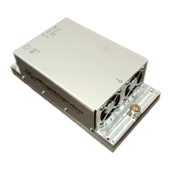
Page 9: Top, Front And Rear Panels View
TOP VIEW SIDE VIEW LEFT AND RIGHT VIEW 1 – control LED (from top to bottom) +24V DC (green) – low voltage +24V DC power supply is applied +HV DC (green) – high voltage +160V DC power supply is applied SYNC IN (orange) –... -
Page 10: Putting The Generator Into Operation
LED “SYNC IN” should light on. High voltage output pulses should be generated. Please check them. Set the external triggering pulses frequency as required, but below or equal to the maximum repetition rate. PPG-5/16 and PPG-7/10 picosecond pulse generators user manual MEGAIMPULSE LTD. - Page 11 Please pay attention that most of the standard GHz range coaxial attenuators are not suitable for direct registration of output pulses because of extremely high peak power. Even 100W and more power attenuators will be broken inevitably. We recommend using of 142 series Barth Electronics attenuator (for the frequencies below 5 kHz) as the first attenuator connected just to the generator output or use a high voltage directional coupler.
-
Page 12: Triggering Of The Generator
+5V on 50 Ohm, pulse duration should be within 10 ns ... 200 ns, rise time should be 1 ns or less. Longer rise time may result in increasing of the output pulse jitter. Fig. 3. Recommended triggering pulse waveform. MEGAIMPULSE LTD. -
Page 13: Warranty
WARRANTY Please see your sales agreement to determine the warranty period and warranty terms. The generator has warranty seals. Removing of the warranty seals terminates the warranty. PPM0731 User Manual...
Need help?
Do you have a question about the PICOSECOND PPM0731 and is the answer not in the manual?
Questions and answers