Table of Contents
Advertisement
Quick Links
Advertisement
Table of Contents

Related Manuals for Megaimpulse PPM0732

Summary of Contents for Megaimpulse PPM0732
- Page 1 PICOSECOND PULSE GENERATOR MODULE PPM0732 USER MANUAL © 2022 Megaimpulse Ltd.
- Page 2 FOR LOSS OF PROFITS, LOSS OF BUSINESS, LOSS OF USE OR DATA, INTERRUPTION OF BUSINESS AND THE LIKE), EVEN IF MEGAIMPULSE LTD. HAS BEEN ADVISED OF THE POSSIBILITY OF SUCH DAMAGES ARISING FROM ANY DEFECT OR ERROR IN THIS MANUAL OR PRODUCT.
-
Page 3: Table Of Contents
Description of the generator operation ............4 Technical specification ................. 7 Top, front and rear panels view ..............8 Bottom view ....................9 Putting the generator into operation .............. 10 Triggering of the generator ................12 Warranty ...................... 13 PPM0732 User Manual... -
Page 4: Safety Manual
SAFETY MANUAL Electrical safety PPM0732 pulse generator module is high voltage equipment. Please be very careful and operate by qualified personnel only. There is a risk of electric shock, strong electromagnetic interference, damage of the generator, or other electronic equipment in case of improper use. -
Page 5: Package Content
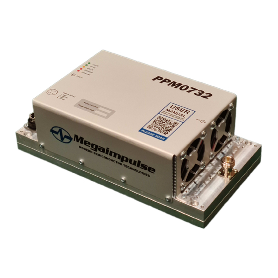
Coaxial cable assembly SMA connector/RG316 cable/SMA connector for the input triggering signal feeding; User manual (printed or electronic version). Fig.1. General view of PPM0732 picosecond pulse generator module. PPM0732 User Manual... -
Page 6: Description Of The Generator Operation
The typical output pulse waveform is shown in Fig.2. Normally the generator should operate on 50 Ohm matched load, for example, UWB antenna connected by 50 Ohm impedance coaxial cable. Fig.2. PPM0732 typical output pulse waveform on matched 50 Ohm load. MEGAIMPULSE LTD. MEGAIMPULSE LTD. - Page 7 168 ns …175 ns. Fig.3. PPM0732 block diagram. The block diagram of PPM0732 is shown in Fig.3. It consists of the control system, DSRD/SAS output stage, power MOSFETs, drivers, as well as the phase detector and variable delay circuit.
- Page 8 Fig.4. Operation of PPM0732 synchronization system. The principle of PPM0732 synchronization system operation is clear from the block-scheme and timing diagram (Fig.3 and Fig.4). The key components are the phase detector and variable delay circuit. The phase detector compares the time position of the output HV pulse and the position of the trailing edge of the triggering pulse.
-
Page 9: Technical Specification
All the parameters are measured after the operation of the generator within 10 minutes at 5 kHz repetition rate. Output pulse amplitude increases with increasing of the repetition rate and may change within ±10% depending on the temperature and operation regime. PPM0732 User Manual... -
Page 10: Top, Front And Rear Panels View
OVERHEAT (red) – too high temperature OVERLOAD (red) – too high repetition rate 2 – Input triggering SMA connector 3 – Power supply connector 4 – 4x mounting holes 4.2 mm dia, 222x118mm footprint 5 – Output HV N-type connector MEGAIMPULSE LTD. -
Page 11: Bottom View
There are five holes on the bottom which give access to the trimmers for the fine-tuning of PPM0732 operation. The holes are closed by the hexagon socket set screws. Please use the hex screwdriver to remove them. The generator has been already adjusted at the factory. -
Page 12: Putting The Generator Into Operation
Step 1. Unpack the generator and check the presence into the package of the following items: PPM0732 pulse generator; Dual voltage AC/DC switching power supply converter with the power supply cable; Semirigid coaxial cable assembly N_connector/SM141_cable/open for the output pulses feeding;... - Page 13 If the frequency of the triggering pulses is too high, then the red LED “OVERLOAD” lights on and the generator stops the operation. Please reduce the frequency of the triggering pulses, LED “OVERLOAD” lights off and the generator continues the operation automatically. PPM0732 User Manual...
-
Page 14: Triggering Of The Generator
+5V on 50 Ohm, pulse duration should be within 10 ns ... 1000 ns, rise and fall time should be 1 ns or less. Longer rise/fall time may result in increasing of the output pulse jitter. Fig. 5. Recommended triggering pulse waveform. MEGAIMPULSE LTD. -
Page 15: Warranty
WARRANTY Please see your sales agreement to determine the warranty period and warranty terms. The generator has warranty seals. Removing of the warranty seals terminates the warranty. PPM0732 User Manual...
Need help?
Do you have a question about the PPM0732 and is the answer not in the manual?
Questions and answers