
Related Manuals for STRATOS FU-230

Summary of Contents for STRATOS FU-230
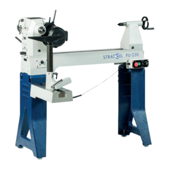
- Page 1 D I E M E I S T E R B A N K STRATOS FU-230 WOOD TURNING L ATHE Original Operating Manual © NEUREITER Original Operating Manual Version 1.0...
- Page 2 Dear customer, Thank you for choosing the Stratos Wood Turning Lathe. The Stratos is a wood turning lathe that combines innova- tions with proven methods. The result of the cooperation between experienced wood turners and engineers is a great value-for-money wood turning lathe that is eminently suitable for beginners, advanced craftsmen, professionals and artists.
-
Page 3: Table Of Contents
Table of contents Explanation of symbols ............3 Locking device (excenter cleat) ........19 Introduction ................ 4 Spindle lock ..............20 1. Basic health and safety notices ........4 24-position indexing ............20 2. Intended Use ..............6 Movable control unit and main switch ......20 3. -
Page 4: Introduction
The design and construction of the Stratos ments that could get caught by the rotating 230 are intended to enable you to work with the machine wi- parts. -
Page 5: Intended Use
• Never climb on the machine and tools. A tilting machine The Stratos 230 Wood Turning Lathe has been designed and or a cutting tool which is accidentally touched can cause built for turning work using wood materials, horn, bone and serious injuries. -
Page 6: Technical Data
3. Technical data Overall dimensions Length x height x depth .......................1,350 mm x 1,250 mm x 500 mm Weight Bench top (without cast iron stand) ..........................113 kg Stand ..................................... 65 kg Total weight .................................. 178 kg Distance between centers ............................700 mm Distance between centers with 400 mm bed extension .................... -
Page 7: Basic Equipment
In order Automatic deactivation to do this, ask someone with experience in wood turning and Stratos is equipped with a zero-voltage switch which deac- have them train you. tivates the lathe in the event of a power outage or when the pulley cover is lifted, and it prevents restarting when the po- At our site, we are offering beginners‘... -
Page 8: Safety Devices
5. Safety devices The safety devices are for the protection of people and material property. Without intact safety devices, severe injuries can be the consequence. Danger! The wood turning lathe must always be used with functioning safety devices. Turn off the lathe immediately on noticing that a safety device is faulty or has been removed! All accessories added by the user must be equipped with the specified safety devices. -
Page 9: Installation Site Requirements
Recommendation Lathe installation site Position the Stratos 230 close to a power source (isolated socket). Ensure the floor is level, solid and stable. Leave sufficient space around the machine. Also consider suffi- cient space for when the headstock has been rotated, for the bed extension and/or the outrigger. -
Page 10: Assembling The Wood Turning Lathe
7. Assembling the wood turning lathe Description of the wood turning lathe 3.2 3.3 1.12 1.10 1.11 Headstock Movable control unit Headstock pivot locking pin Stop rod Headstock clamping lever Handwheel Tailstock Pulley cover Live center Rubber tray Quill Motor clamping lever Quill fine adjustment (on the rear) Quick-release lever for motor locking mechanism Quick-release lever for quill locking... -
Page 11: Delivery Contents
Assembly information: We carefully packaged the machine at our site. Upon receipt, please check the packaging for damage or whether the machine has become damaged during transport as well as whether the contents are complete. In the event of complaints, please report them to your supplier immediately and do not start using the machine. - Page 12 Delivery contents Lathe bed with headstock, tailstock, tool rest support with tool rest 350 mm (1“ stems). Stand. Live center with integrated ring and center point live center, MT2 Spur center 25 mm, MT2. Knock out bar. Feet, height adjustable, 8 x 3/8“ x 50 mm. Bolts 8 x 3/8“...
- Page 13 Danger! • During machine assembly, always make sure that your fingers do not get trapped in between the parts. Risk of crushing! • Be aware of the weight of the individual components and handle them carefully to avoid causing yourself any injuries.
- Page 14 Make sure that cables do not get damaged. Using two people, lift the empty lathe bed onto the stand and align it. Now fix the lathe bed to the stand with the remaining two bolts. First, hand-tighten the bolts so you can adjust the lathe bed and the feet after removing the bar clamp.
- Page 15 Now insert the stainless steel handle (N) into the specified socket on the motor flange to tighten the drive belt. Attach the holder for the movable control unit to the front right of the lathe bed. The tool holder is attached to the opposite rear of the lathe bed.
-
Page 16: Easy Quick-Release System (Available As An Option)
The wood turning lathe has been assembled. Easy quick-release system (available as an option) Art. DDSTR-AS This high quality equipment enables rapid replacement of the lathe bed extension and the outrigger. This accessory is not part of the shipment. Assembling the bed extension (available as an option) Art. - Page 17 Combined bed extension/outrigger (available as an option) Art. DDSTR-BV400N Made of 400 mm cast iron extension and shaft extension for tool rest. Can be used on three fixing points! Can be used for Stratos and Twister. © NEUREITER | Original Operating Manual Version 1.0...
-
Page 18: Connecting The Wood Turning Lathe To The Mains Supply
7. Connecting the wood turning lathe 8. Commissioning to the mains supply To begin with, check that the machine has been set up and The operator must use an isolated socket fused with 16 amp. assembled correctly. Before commissioning, remove all loose The mains voltage and rating must correspond to the data on parts and tools that may be lying on the lathe. -
Page 19: Tailstock
Tailstock In order to move the tailstock on the lathe bed, loosen the clamping lever, move the tailstock to the required position Never loosen the quill on the tailstock or the tailstock itself and secure it there again. while the work piece is rotating. The tailstock is equip- ped with a MT2 quill. -
Page 20: Spindle Lock
Spindle lock The spindle lock can be activated by a 90° turn. The spindle has a total of 9 location holes for locking. Activate the spind- le lock in order to loosen the chuck etc. from the spindle. It is essential that the motor is not turned on during locking of the spindle. -
Page 21: Recommended Speed Range
Recommended speed range Look for the work piece diameter. Determine the intersection to the speed with a vertical line. From this point, go left and determine the speed (rpm). Recommended speed range for general woodturning Recommended speed range for general woodturning on the outrigger ©... -
Page 22: Speed Range Using Pulley Change
Speed range using pulley change Stage I The motor drives the spindle pulleys via 2 wide pulleys using a Stage II Poly-V belt. A slower belt speed is needed for work with larger diameters in order to maintain an ideal torque. This means that if you have turned a spinning top for example and then want to turn a bowl with a diameter of 30 cm or more, the motor output might be reduced under heavy use. -
Page 23: Replacing The Belt
Motor lever If you ever need to replace a faulty belt, this is very easy with the Stratos lathe. Disconnect the mains plug and only then open the cover (A). the spindle shaft and belt cover and then placed on the pulleys. -
Page 24: Processing Work Pieces
Processing work pieces Danger! Warning! • Always use eye protection. • In the event of a power outage, the work piece will continue to spin freely. The ma- • Make sure the work piece has been secu- chine slowing down can take some time. rely clamped in position. - Page 25 Mounting side grain between centers length, towards the opposite end. Using the clamping lever, position the tailstock tightly on the rear of the lathe bed. By Ideal centering is essential because any imbalance has to turning the handwheel, push the live center into the cen- be minimized, in particular for large work pieces.
- Page 26 Positioning of the blade support or tool rest for side grain So-called „fillets“ are cut with the beading tool or cut-off tool. The tool engages above the center. When roughing, set the tool rest slightly below the spind- le center line so the blade can engage slightly above the middle.
-
Page 27: Outrigger
The Stratos offers you the opportunity to turn work pieces with a larger diameter than 45 cm. You have the choice of attaching the outrigger at the front left under the headstock or on the right outside surface of the right stand. -
Page 28: Care And Maintenance
If processing or material faults occur during the intended use of the Stratos • When the machine has been decommissi- 230, they will be repaired or replaced by your relevant sales oned, the rules and regulations applicable at partner at his expense and choice. -
Page 29: Troubleshooting Guide
or another legal provision. requirements for these may differ from those specified above. Please note that distributors in Austria and Germany may have Therefore, please contact your local distributor in the event of their own warranty conditions concerning this product. The problems. -
Page 30: Appendices
Gewerbegebiet Am Brennhoflehen Kellau 167 A-5431 KUCHL dass die Maschine: Drechselbank Typ: Stratos FU – 230 Seriennr.: von 10500 bis 11000 in der aufgestellten Ausführung folgenden einschlägigen Bestimmungen entspricht: • EG-Richtlinie 2006/42/EG über Maschinen • EG-Richtlinie 2004/108/EG über die elektromagnetische Verträglichkeit Die Schutzziele der Niederspannungsrichtlinie 2006/95/EG wurden gemäß... -
Page 31: Appendix 2 Spare Parts Lists
Appendix 2: Spare parts lists Parts list A, Headstock Position- Part no. Description Specification Quantity number KS18-A01 Spur center KS18-A02 Face plate 150mm x M33 KS18-A03 Allen set screw 1/4x3/8“ KS18-A04 Spindle M33x3.5mm KS18-A05 Round-head screw 1/4“x5/16“ KS18-A06 6x6x50 KS18-A07 4x4x10 KS18-A08 Bearing... - Page 32 KS18-A19 Motor rating plate KS18-A20 Motor 230V 50Hz KS18-A21 Spring washer 3/8“ KS18-A22 Machine screw 3/8-16unc x 1-3/4 KS18-A23 Cable retainer ACC5 KS18-A24 Cable bushing PG13.5 KS18-A25 Round-head screw M3X18 KS18-A26 Circuit breaker-1 14 V KS18-A27 Single-wire cable 2 KS18-A28 Bearing 6205 KS18-A29...
- Page 33 KS18-A66 Movable control unit 66/1 KS18-A66-1 Forward/reverse switch 66/2 KS18-A66-2 Switch protector 66/3 KS18-A66-3 Button, green 66/4 KS18-A66-4 Button, red 66/5 KS18-A66-5 Speed controller 66/6 KS18-A66-6 Speed controller knob 66/7 KS18-A66-7 Housing 66/8 KS18-A66-8 Magnet 66/9 KS18-A66-9 Strain relief 66/10 KS18-A66-10 Cable 66/11...
-
Page 34: Parts List B, Lathe Bed, Tool Rest, Tailstock
Parts list B, Lathe bed, tool rest, tailstock Position- Part no. Description Specification Quantity number KS18-B01 Handwheel handle KS18-B02 Handwheel 6“x19 KS18-B03 Set screw 1/4x1/4 KS18-B04 Tailstock KS18-B05 Quick-release lever 5/16“ KS18-B06 Clamping lever KS18-B07 Stop rod KS18-B08 Quill fine adjustment M10x30 KS18-B09 KS18-B10... - Page 35 KS18-B14 Bushing KS18-B15 KS18-B16 Fixing ring KS18-B17 Nylon nut 3/4“ x 10unc KS18-B18 KS18-B19 Clamping lever KS18-B20 Circlip S-22 KS18-B21 Brass bush KS18-B22 Quick-release lever KS18-B23 Schnellspannhebel 3/8“ KS18-B24 Tool rest 14“ KS18-B25 Rear cover plate KS18-B26 Round-head screw #10-24unc x 5/16“ KS18-B27 Strain relief PGll...
-
Page 36: Parts List C, Stand
Parts list C, Stand Position- Part no. Description Specification Quantity number KS18-C01 Stand (for left and right-hand use) KS18-C02 Washer 3/8“ KS18-C03 Spring washer 3/8“ KS18-C04 Hexagon bolt 3/8“ -16 x 1-l/2 KS18-C05 3/8“ KS18-C06 Level adjusting feet 3/8“ © NEUREITER | Original Operating Manual Version 1.0... -
Page 37: Appendix 3 Circuit Diagram
Appendix 3: Circuit diagram Circuit diagram key B1 Spindle speed sensor SA2 Rotational direction switch FB2 Emergency stop/OFF button SB1 ON button FU1 Fine-wire fuse SK Safety plug M1 Electric motor U1 Frequency converter VFD-S SA1 Main switch VR 1 Speed controller (poti) ©... - Page 38 © NEUREITER | Original Operating Manual Version 1.0...
-
Page 39: Appendix 4 Drilling Template, Auxiliary Support (For Cutting Out/Printing)
Appendix 4: Drilling template, auxiliary support (for cutting out/printing) see page 13 © NEUREITER | Original Operating Manual Version 1.0...
Need help?
Do you have a question about the FU-230 and is the answer not in the manual?
Questions and answers