Table of Contents
Advertisement
Advertisement
Table of Contents

Related Manuals for STRATOS FU-230

Summary of Contents for STRATOS FU-230
- Page 1 FU-230 WOOD TURNING LATHE...
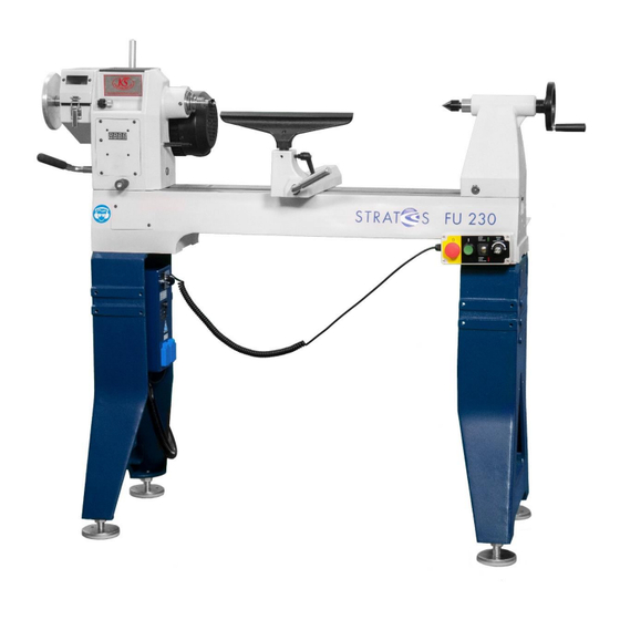
- Page 2 Dear Customer, Thank you for choosing the Stratos Wood Turning Lathe. The Stratos is a wood turning lathe that combines innovations with proven methods. The result of the cooperation between experienced wood turners and engineers is a great value-for-money wood turning lathe that is eminently suitable for beginners, advanced craftsmen, professionals, and artists.
-
Page 3: Table Of Contents
able of contents Explanation of symbols ......................- 4 - Introduction..........................- 5 - Basic health and safety notices..................- 5 - Intended Use........................- 7 - Technical data........................- 8 - Basic equipment..........................- 8 - Optional accessory...........................- 8 - Description of functions....................- 9 - Safety devices......................- 10 - EMERGENCY STOP/OFF and ON Function..................- 10 - Warning signs on the wood turning lathe.................. -
Page 4: Explanation Of Symbols
Parts list B, Lathe bed, tool rest, tailstock ..................- 42 - Parts list C, Stand ........................- 44 - Appendix 3 Circuit diagram......................- 45 - Appendix 4 Drilling template, auxiliary support (for cutting out/printing) ..........- 46 - Explanation of symbols Use eye protection Use breathing protection Use hearing protection... -
Page 5: Introduction
This handbook contains instructions for assembly, safety notices, general operating and maintenance instructions and spare parts lists. The design and construction of the Stratos 230 are intended to enable you to work with the machine without problems for many years, if you comply with the recommendations specified in this manual. - Page 6 • Do not work in a damp and dangerous environment. The Stratos Wood Turning Lathe has been exclusively designed for use indoors. Protect the wood turning lathe from damp and humid locations. Do not subject the machine to moisture. Ensure the working environment is sufficiently lit and ventilated. Avoid areas with an explosive atmosphere.
-
Page 7: Intended Use
Turn off the wood turning lathe every now and then in order to position the tool rest ideally. 2. Intended Use The Stratos 230 Wood Turning Lathe has been designed and built for turning work using wood materials, horn, bone and plastics in small sizes. Processing of other materials is not permitted or may only take... -
Page 8: Technical Data
3. Technical data Overall dimensions Length x height x depth ................1,350 mm x 1,250 mm x 500 mm Weight Bench top (without cast iron stand) ....................113 kg Stand ..............................65 kg Total weight ............................. 178 kg Distance between centres ......................700 mm Distance between centres with 400 mm bed extension ............... -
Page 9: Description Of Functions
(headstock) and live centre (tailstock) or a particular clamping device (chuck, face plate) and driven via an electric motor. Drive is from an electric motor via pulleys to the spindle. Stratos has two speed stages (gear ratios) that you can select. Fine-tuning of the speed takes place via frequency conversion which is regulated by a potentiometer (POTI in short) on the movable control unit, so you can sleeplessly set the speed in the respective speed stage. -
Page 10: Safety Devices
5. Safety devices The safety devices are for the protection of people and material property. Without intact safety devices, severe injuries can be the consequence. Danger! The wood turning lathe must always be used with functioning safety devices. Turn off the lathe immediately on noticing that a safety device is faulty or has been removed! All accessories added by the user must be equipped with the specified safety devices. -
Page 11: Installation Site Requirements
Requirement Recommendation Lathe installation site Position the Stratos 230 close to a power source (isolated socket). Ensure the floor is level, solid and stable. Leave sufficient space around the machine. Also consider sufficient space for when the headstock has been rotated, for the bed extension and/or the outrigger. -
Page 12: Assembling The Wood Turning Lathe
7. Assembling the wood turning lathe Description of the wood turning lathe lj8) Tool rest support •S ST AT Lathe bed Stand 5 .1 Fin '.1 1 Headstock 2.5 Movable control unit 1.1 Headstock pivot locking pin 2.6 Stop rod 1.2 Headstock clamping lever 3 Tailstock 1.3 Handwheel... - Page 13 During assembly, put the headstock down in such a way that the cable connections are not damaged, and the cables are not disconnected under any circumstances. • The cast iron stand was developed for use with the Stratos 230. Using it with other machines can lead to injury. Tool and resource recommendations for assembly: •...
- Page 14 Delivery contents A Lathe bed (see Fig. 15) with headstock, tailstock, tool rest support with tool rest 350 mm (1“stems). B Stand (see Fig. 10). C Live centre D Spur centre 25 mm, MT2. E Knock out bar. F Feet, height adjustable, 8 x 3/8“ x 50 mm (Fig. 12). G Bolts 8 x 3/8“...
- Page 15 Fig. 12 Fig. 11 Holder for movable control unit Fig. 10 Stand Danger! • During machine assembly, always make sure that your fingers do not get trapped in between the parts. Risk of crushing! • Be aware of the weight of the individual components and handle them carefully to avoid causing yourself any injuries.
- Page 16 Attach the prepared timber board (use the drilling template Appendix 4) to the fixing points (see Fig. 14) on the left stand for the outrigger using the supplied 3/8“ bolts. Then align the stand in such a way that it is flush with the board and secure the board on the right stand using a bar clamp.
- Page 17 Fig. 18 Putting down the headstock Fig. 17 Fig. 19 Placing the lathe bed onto the stand Now fix the lathe bed to the stand with the remaining two bolts. First, hand-tighten the bolts so you can adjust the lathe bed and the feet after removing the bar clamp. After tightening the two bolts on the lathe bed, you can remove the timber board and tightly connect the lathe bed using the supplied bolts.
- Page 18 Using the spirit level, check that the lathe bed is level. If required, adjust the lathe using the feet. Fig. 21 Fig. 22 Using two people, carefully lift the headstock into the lathe bed guide. Fig. 23 First, place the tool rest support on the lathe bed, then the tailstock. Now replace the stops (stop rod and stop plate) at the ends of the lathe bed.
- Page 19 Fig. 25 Now insert the stainless-steel handle (N) into the specified socket on the motor flange to tighten the drive belt. Fig. 26 Attach the holder for the movable control unit to the front right of the lathe bed. The tool holder is attached to the opposite rear of the lathe bed (Fig. 7). Both parts are secured with two Allen set screws each from the inside of the lathe bed.
- Page 20 Aligning the headstock Loosen the headstock and rotate it so it is aligned with the lathe bed and the tailstock. Mount the double ended Morse taper (H) in the tailstock and, using the tailstock, insert it into the spindle so that it slides in without resistance.
-
Page 21: Easy Quick-Release System (Available As An Option)
Invertor now fits here with 4 x M5 socket head screws. Fig. 30 The wood turning lathe has been assembled. Easy quick-release system (available as an option) This high-quality equipment enables rapid replacement of the lathe bed extension and the outrigger (Fig. 31 and 35). -
Page 22: Assembling The Bed Extension (Available As An Option)
Assembling the bed extension (available as an option) The bed extension can be used to extend the lathe bed and for the outrigger. This accessory is not part of the shipment. 1. Before attaching the bed extension, push the tailstock away from the end of the lathe bed and remove the stop rod. -
Page 23: Connecting The Wood Turning Lathe To The Mains Supply
7. Connecting the wood turning lathe to the mains supply The operator must use an isolated socket fused with 16 amp. The mains voltage and rating must correspond to the data on the lathe's rating plate. The building must be equipped with mains protection which is connected to the lathe's safety plug. The supplied safety plug must be used with a suitable isolated socket which has been appropriately installed, according to country-specific electrical regulations. -
Page 24: Tailstock
Replacing the spur centre Using the supplied knock out bar, the spur centre can be pushed out from the rear through the spindle shaft. Initially, try to push out the spur centre with gentle taps. During this process, carefully hold on to the outside of the spur centre with your other hand. -
Page 25: Locking Device
Locking device (excentre cleat) If the headstock, tailstock, or tool rest support cannot be secured on the lathe bed, the excentre cleat must be readjusted. Pull the headstock, tailstock, or tool rest support to the end of the lathe bed and loosely tighten the self-locking nut (see image). -
Page 26: Movable Control Unit And Main Switch
Movable control unit and main switch Main switch Position the main switch to ZERO (0) to turn the machine off and to ON (I) to turn it on (Fig. 47). The main switch should be used only at the beginning and the end of the wood turning work. -
Page 27: Recommended Speed Range
Recommended speed range 1. Look for the work piece diameter. 2. Determine the intersection to the speed with a vertical line. 3. From this point, go left and determine the speed (rpm). A. Recommended speed range for general woodturning Recommended speed range Work piece diameter in mm Roughing of work pieces General woodturning... - Page 28 Changing the speed range by sliding the belt The motor drives the spindle pulleys via 2 wide pulleys using a Poly-V belt. A slower spindle speed is needed for work with larger diameters to maintain an ideal torque. This means that if you have turned a spinning top for example and then want to turn a bowl with a diameter of 30 cm or more, the motor output might be reduced under heavy use.
- Page 29 If you ever need to replace a faulty belt, this is very easy Motor lever with the Stratos lathe. Disconnect the mains plug and only then open the cover (A). Loosen the quick-release lever (S) on the motor and, using the chromium-plated clamping lever, pull the motor toward the headstock.
-
Page 30: Processing Work Pieces
Processing work pieces Danger! • Always use eye protection. • Make sure the work piece has been securely clamped in position. Always start with a slower speed and increase it to the ideal speed. • If the speed is too high, unbalanced work pieces can be ejected from the lathe and cause severe injuries. - Page 31 Mounting side grain between centres Ideal centring is essential because any imbalance must be minimized, in particular for large work pieces. A deep indentation by the spur centre also increases safe holding of the work piece during woodturning. Take a square-ended piece of wood and determine the centre on both ends. For this, join the diagonals with a pencil line (see Fig.
- Page 32 Compare this to working with a plane. If the plane is moved slowly, it is much harder to break the fibres. ´ Fixing end grain on a face plate End grain blanks must be sawn as round as possible with a band saw before securing them on a lathe. This makes the start of the woodturning process easier and reduces vibrations.
-
Page 33: Outrigger
During rotation of the work pieces, much higher forces occur than when woodturning over the lathe bed. The Stratos offers you the opportunity to turn work pieces with a larger diameter than 45 cm. You have the choice of... - Page 34 In order to use the outrigger (Fig. 66 and 67), attach the lathe bed extension (B) (only available as an option) to the designated anchor points (A) on the stand using the supplied mounting kit (G, Fig. 6). Loosen the clamping lever (K, Fig.
-
Page 35: Care And Maintenance
10. Care and maintenance Maintenance/machine care: After each use, particularly in the event of high humidity, the Stratos wood turning lathe should be protected on all parts susceptible to corrosion such as the lathe bed, spindle thread with MT2-bore and quill with MT2-bore as well as some screw threads, using appropriate wax, silicone spray or other rust protection. -
Page 36: Warranty Conditions
This product has a two-year manufacturer warranty from the purchase date in addition to the legal warranty. If processing or material faults occur during the intended use of the Stratos 230, they will be repaired or replaced by your relevant sales partner at his expense and choice. The requirement for this... -
Page 37: Troubleshooting Guide
13. Troubleshooting guide Description of problem Possible cause Possible solution • • No power Check mains fuse Machine does not turn on • • Motor, switch, or cable faulty Contact an electrician • • Cover not properly closed Close the cover and secure it •... -
Page 38: Appendices
14. Appendices Appendix 1 Declaration of Conformity © - 38 - Translation of the Original Instruction Manual Version 1.0 Drechselbedarf Schulte... -
Page 39: Appendix 2
Appendix 2 Spare parts lists Parts list A, Headstock Fig. 68 Position Part no. Description Specification Quantity number KS18-A01 Spur centre KS18-A02 Face plate 150 mm x M33 KS18-A03 Allen set screw 1/4x3/8" KS18-A04 Spindle M33x3.5 mm KS18-A05 Round-head screw 1/4"x5/16"... - Page 40 Position Part no. Description Specification Quantity number KS18-A18 Quick-release lever 3/8" KS18-A19 Motor rating plate KS18-A20 Motor 230V 50Hz KS18-A21 Spring washer 3/8" KS18-A22 Machine screw 3/8-16unc x 1-3/4 KS18-A23 Cable retainer ACC5 KS18-A24 Cable bushing PG13.5 KS18-A25 Round-head screw M3X18 KS18-A26 Circuit breaker 1...
- Page 41 Position Part no. Description Specification Quantity number KS18-A60 Control plate KS18-A61 Machine screw M3x10 KS18-A62 #10-24 KS18-A63 Toothed washer #10-24 KS18-A64 Acrylic control panel KS18-A65 Face plate wrench KS18-A66 Movable control unit 66/1 KS18-A66-1 Forward/reverse switch 66/2 KS18-A66-2 Switch protector 66/3 KS18-A66-3 Button, green...
- Page 42 Parts list B, Lathe bed, tool rest, tailstock Fig. 69 Position Part no. Description Specification Quantity number KS18-B01 Handwheel handle KS18-B02 Handwheel 6" x19 KS18-B03 Set screw 1/4x1/4 KS18-B04 Tailstock KS18-B05 Quick-release lever 5/16" KS18-B06 Clamping lever KS18-B07 Stop rod KS18-B08 Quill fine adjustment M10x30...
- Page 43 Position Part no. Description Specification Quantity number KS18-B15 KS18-B16 Fixing ring KS18-B17 Nylon nut 3/4" x 10unc KS18-B18 KS18-B19 Clamping lever KS18-B20 Circlip S-22 KS18-B21 Brass bush KS18-B22 Tool rest support base KS18-B23 Quick-release lever 3/8" KS18-B24 Tool rest 14" KS18-B25 Rear cover plate KS18-B26...
- Page 44 Parts list C, Stand Fig. 70 Position Part no. Description Specification Quantity number KS18-C01 Stand (for left and right-hand use) KS18-C02 Washer 3/8" KS18-C03 Spring washer 3/8" KS18-C04 Hexagon bolt 3/8" -16 x 1-l/2 KS18-C05 3/8" KS18-C06 Level adjusting feet 3/8"...
- Page 45 Appendix 3 Circuit diagram ON/OFF Safety plug Speed display U1 Frequency converter + sensor Delta VFD-S 015S21U Green button ON SB1 Emergency stop + OFF Red button Toggle switch for forward and reverse operation Movable control unit Disconnect switch Cover Braking resistor 80 W 200 Ohm Electric motor...
- Page 46 Appendix 4 Drilling template, auxiliary support (for cutting out/printing) t ------- " 1.150 mm total board length Hole Ø 9 mm ---- - •-. - • Place at board edge 50 mm 134,6 mm 20 mm - -- Hole Ø 9 mm 125 mm Fig.
Need help?
Do you have a question about the FU-230 and is the answer not in the manual?
Questions and answers