Sign In
Upload
Download
Table of Contents
Contents
Add to my manuals
Delete from my manuals
Share
URL of this page:
HTML Link:
Bookmark this page
Add
Manual will be automatically added to "My Manuals"
Print this page
×
Bookmark added
×
Added to my manuals
Manuals
Brands
Menumaster Manuals
Microwave Oven
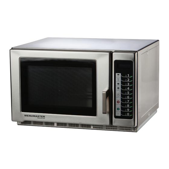
RFS Series
Service training manual
Menumaster RFS Series Service Training Manual
Hide thumbs
1
Table Of Contents
2
3
4
5
6
7
8
9
10
11
12
13
14
15
16
17
18
19
20
21
22
23
24
25
26
27
28
29
30
31
32
33
34
page
of
34
Go
/
34
Contents
Table of Contents
Troubleshooting
Bookmarks
Table of Contents
Table of Contents
Important Safety Information
RFS 50 Hz Specifications
Installation
Specifications
Quick Start Reference Guide
Components
Disassembly
Performance Testing Procedures
Component Testing Procedures
Troubleshooting
Schematic / Wiring Diagram
Advertisement
Quick Links
Download this manual
Service Training Manual
RFS Models
RFS - 50 Hz
September 2011
16400015
Table of
Contents
Previous
Page
Next
Page
1
2
3
4
5
Advertisement
Table of Contents
Need help?
Do you have a question about the RFS Series and is the answer not in the manual?
Ask a question
Questions and answers
Related Manuals for Menumaster RFS Series
Microwave Oven Menumaster RFS518TS Service Training Manual
(34 pages)
Microwave Oven Menumaster RCS511DSE Owner's Manual
Commercial microwave oven (61 pages)
Microwave Oven Menumaster CFSP70 Use And Care Manual
Commercial (12 pages)
Microwave Oven Menumaster DEC1800VP series Owner's Manual
(212 pages)
Microwave Oven Menumaster Jetwave JET14 Series Service Training Manual
High speed combination oven (67 pages)
Microwave Oven Menumaster UC1800VP Series Owner's Manual
International commercial microwave oven (16 pages)
Microwave Oven Menumaster DECS11MA Service Manual
(44 pages)
This manual is also suitable for:
Rfs518ts
Table of Contents
Save PDF
Print
Rename the bookmark
Delete bookmark?
Delete from my manuals?
Login
Sign In
OR
Sign in with Facebook
Sign in with Google
Upload manual
Upload from disk
Upload from URL


Need help?
Do you have a question about the RFS Series and is the answer not in the manual?
Questions and answers