International commercial microwave oven (16 pages)
Summary of Contents for Menumaster DECS11MA
Page 1
Microwave Oven Service Manual DECS11MA DES11EA DFS11G DFS11EA UCS11MA US11EA UFS11EA CAUTION BEFORE SERVICING THE UNIT, READ THE SAFETY PRECAUTIONS IN THIS MANUAL.
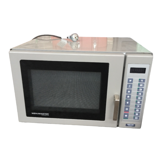
SAFETY PRECAUTIONS This device is to be serviced only by properly qualified service personnel. Consult the service manual for proper service procedures to assure continued safety operation and for precautions to be taken to avoid possible exposure to excessive microwave energy. PRECAUTIONS TO BE OBSERVED BEFORE AND DURING SERVICING TO AVOID POSSIBLE EXPOSURE TO EXCESSIVE MICROWAVE ENERGY...
CAUTIONS Unlike other appliances, the microwave oven is MICROWAVE RADIATION high-voltage and high-current equipment. Personnel should not be exposed to the Though it is free from danger in ordinary use, microwave energy which may radiate from the extreme care should be taken during repair. magnetron or other microwave generating device if it is improperly used or connection.
INSTALLATIONS BEFORE YOU BEGIN, READ THE FOLLOWING INSTRUCTIONS COMPLETELY AND CAREFULLY. EARTHING INSTRUCTIONS INSTALLING This microwave oven is designed to be used in a fully 1. Empty the microwave oven and clean inside it with earthed condition. a soft, damp cloth. Check for damage such as It is imperative, therefore, to make sure it is properly misaligned door, damage around the door or dents earthed before servicing...
OPERATING INSTRUCTIONS FEATURES Window Door Screen Electronic Control Safety Door Lock System CONTROL PANEL Display Some items in display can be seen but will not glow. Pads TIME ENTRY Use to enter heating time without changing preprogrammed number pads. Pads 1-0 Use to begin heating with preprogrammed times and power levels or to enter times for “Manual Time Entry”...
Page 8
OPERATING INSTRUCTIONS FEATURES Window Door Screen Electronic Control Safety Door Lock System CONTROL PANEL Display Some items in display can be seen but will not glow. Pads TIME ENTRY Use to enter heating time without changing preprogrammed number pads. Pads 1-0 Use to begin heating with preprogrammed times and power levels or to enter times for “Manual Time Entry”...
Page 9
70%, full or reduced power. 50%, DEFROST START Use to start “Manual Time Entry” program or restart interrupted cooking cycle. Use to advance to next user option. Use to save times and power levels when programming pads. DECS11MA / UCS11MA...
Page 10
OPERATING INSTRUCTIONS FEATURES Window Door Screen Electronic Control Safety Door Lock System Display CONTROL PANEL Some items in display can be seen but will not glow. Pads TIME ENTRY Use to enter heating time without changing preprogrammed number pads. Pads 1-0 Use to begin heating with preprogrammed times and power levels or to enter times for “Manual Time Entry”...
Cooking Displays Cooking Displays Cooking Displays Cooking Displays Shows when power is connected to oven. Open and close door to clear. READY shows when oven control will accept entries. Appears after oven door is opened and closed. 33:33 shows heating time. When more than 1 heating stage is programmed, total time for all stages displays.
OPERATION Preprogrammed Times and Cook Level All preprogrammed pads arrive set at full power. CAUTION To avoid fire,do not dry newspapers or clothes in Option: Single Digit Option: Double Digit microwave oven. Heating Heating Heating Pads Pads Pads Times Times Times Interrupting Operation 10 sec.
PROGRAMMING Preprogrammed Number Pads Multiple Heating Stages Oven has 10~20 preprogrammed number pads. Follow Follow instructions below to program oven to perform 3 instructions below to program heating times and power consecutive heating cycles without interruption. levels for customized cooking. 1.
Page 14
User Options 4. Press START pad to advance to next option. See table for options. Follow the instructions below to customized the 5. Press number pad (0,1-3) to change option. microwave oven’s operation. End-of-cycle signal, 6. Press START pad to save changes. maximum heating time and other options can be •...
CIRCUIT DESCRIPTION • A high voltage of approximately 2100 volts AC is GENERAL DETAILS generated in the secondary of the high voltage • The low voltage transformer supplies the necessary transformer which is increased by the action of the high voltage to the micom controller when power cord is voltage diode and charging of the high voltage plugged in.
SERVICE INFORMATION TOOLS AND MEASURING INSTRUMENTS NECESSARY TOOLS NECESSARY MEASURING INSTRUMENTS • TESTER(VOLTS-DC, AC, Ohmmeter) Tools normally used for TV servicing are sufficient. • Microwave survey meter Standard tools are listed below. - Holaday HI-1500 • Diagonal pliers HI-1501 • Long nose pliers - Narda 8100 •...
Page 18
MEASUREMENT WITH OUTER CASE NOTES WHEN MEASURING REMOVED • Do not exceed meter full scale deflection. • The test probe must be removed no faster than • When you replace the magnetron, measure for 1 inch/sec (2.5 cm/sec) along the shaded area, microwave energy leakage before the outer case is otherwise a false reading may result.
MEASUREMENT OF MICROWAVE POWER OUTPUT • Microwave power output measurement is made with • The microwave power output P in watts is calculated the microwave oven supplied at its rated voltage and from the following formula : operated at its maximum microwave power setting with 4187 x (∆T) a load of (1000±5) g of potable water.
Page 20
D. PCB ASSEMBLY REMOVAL Remove choke cover 1) Remove the control panel assembly from the cavity. (Refer to control panel assembly removal on previous page.) 2) Remove screws which hold the PCB SUB ASS’Y to the control panel. 3) Disconnect the flat cable from the PCB SUB ASS’Y and take off the PCB SUB ASS’Y PCB Sub Asm Control Panel...
Page 21
F. MAGNETRON REMOVAL G. REMOVING THE STIRRER FAN MOTOR 1) Disconnect the leadwire from the magnetron. 2) Carefully remove the mounting screws holding the 1) Disconnect the leadwire from the stirrer fan motor magnetron and the waveguide. terminals. 3) Remove the magnetron ASS’Y until the tube is 2) Remove the screw securing the stirrer fan motor to clear from the waveguide.
Page 22
H. HIGH VOLTAGE TRANSFORMER K. INTERLOCK SYSTEM REMOVAL 1) INTERLOCK MECHANISM The door lock mechanism is a device which has 1) Discharge the high voltage capacitor. been specially designed to eliminate completely 2) Disconnect the leadwire from magnetron, high voltage microwave activity when the door is opened during transformer, and capacitor.
INTERLOCK CONTINUITY TEST WARNING : FOR CONTINUED PROTECTION AGAINST EXCESSIVE RADIATION EMISSION, REPLACE ONLY WITH IDENTICAL REPLACEMENT PARTS. TYPE NO. SZM-V 21-FC-93 FOR PRIMARY SWITCH TYPE NO. SZM-V 16-FD-62 OR V-16-2C 25 FOR MONITOR SWITCH TYPE NO. SZM-V 16-FD-63 OR V-16-3C 25 FOR SECONDARY SWITCH B.
COMPONENT TEST PROCEDURE CAUTIONS 1. DISCONNECT THE POWER SUPPLY CORD FROM THE OUTLET WHENEVER REMOVING THE OUTER CASE FROM THE UNIT. PROCEED WITH THE TEST ONLY AFTER DISCHARGING THE HIGH VOLTAGE CAPACITOR AND REMOVING THE WIRE LEADS FROM THE PRIMARY WINDING OF THE HIGH VOLTAGE TRANSFORMER.
Page 25
COMPONENTS TEST PROCEDURE RESULTS Antenna Antenna Antenna Antenna Antenna Antenna Antenna Antenna Gasket Gasket Gasket Gasket Gasket Gasket Gasket Gasket Chassis Chassis Chassis Chassis Chassis Chassis Chassis Chassis Filament Filament Filament Filament Filament Filament Filament Filament NOTE: When testing the magnetron, be sure to install the magnetron gasket in the correct position and be sure that the gasket is in good condition.
Page 26
COMPONENTS TEST PROCEDURE RESULTS Check for continuity of relay 2 with an POWER RELAY 2 ohm-meter. LEVEL (Remove wire leads from relay 2 and 3 sec 9 sec operate the unit.) 4 sec 8 sec 5 sec 7 sec 6 sec 6 sec 7 sec 7 sec...
TROUBLE SHOOTING TROUBLE SHOOTING TROUBLE SHOOTING TROUBLE SHOOTING WHEN YOU GET A COMPLAINT FROM YOUR CUSTOMER, EVALUATE THE COMPLAINT CAREFULLY. IF WHEN YOU GET A COMPLAINT FROM YOUR CUSTOMER, EVALUATE THE COMPLAINT CAREFULLY. IF WHEN YOU GET A COMPLAINT FROM YOUR CUSTOMER, EVALUATE THE COMPLAINT CAREFULLY. IF WHEN YOU GET A COMPLAINT FROM YOUR CUSTOMER, EVALUATE THE COMPLAINT CAREFULLY.
Page 28
(TROUBLE 1) The following visual conditions indicate a probable defective control circuit. 1. Incomplete segments. • Segment missing. • Partial segment missing. • Digit flickering (NOTE: Slight flickering is normal.) 2. Colon does not turn on or blink. 3. A distinct change in the brightness of one or more numbers in display. 4.
Page 29
(TROUBLE 2) Oven does not operate at all, Display window does not display any figures, Oven does not operate at all, Display window does not display any figures, and no input is accepted. and no input is accepted. CONDITION CHECK RESULT CAUSE REMEDY...
Page 30
(TROUBLE 3) Display shows all figures set, but oven does not start cooking while desired (TROUBLE 3) Display shows all figures set, but oven does not start cooking while desired (TROUBLE 3) Display shows all figures set, but oven does not start cooking while desired (TROUBLE 3) Display shows all figures set, but oven does not start cooking while desired program times are set and START pad is touched.
Page 31
(TROUBLE 5) No microwave oscillation even though oven lamp and blower motor run. (Display operates properly) CONDITION CHECK RESULT CAUSE REMEDY Disconnect the No microwave Defective PCB Replace PCB No continuity. wire leads from oscillation. assembly. assembly. and check relay 3 continuity of relay 3 Continuity.
#EV# EXPLODED VIEW INTRODUCTION MODEL : DFS11G DECS11MA UCS11MA OVEN CAVITY PARTS INTERIOR PARTS BASE PLATE PARTS DOOR PARTS LATCH BOARD PARTS CONTROL PANEL PARTS...
Page 33
#EV# INTRODUCTION MODEL : DES11EA DFS11EA US11EA UFS11EA OVEN CAVITY PARTS INTERIOR PARTS BASE PLATE PARTS DOOR PARTS LATCH BOARD PARTS CONTROL PANEL PARTS...
Page 34
#EV# DOOR PARTS MODEL : DFS11G DECS11MA UCS11MA DES11EA DFS11EA US11EA UFS11EA 1013 1005 1004 1385 1002 1000 W136 1006 1007 W105 W108 1384 1009 1386 W206 W207...
Page 35
#EV# CONTROL PANEL PARTS MODEL : DFS11G 2012 W102 2006 2381 W130 2000 2005 2400...
Page 36
#EV# CONTROL PANEL PARTS MODEL : DECS11MA UCS11MA 2012 W102 2381 2006 2002 W130 2000 2005 2400...
Page 37
#EV# CONTROL PANEL PARTS MODEL : DES11EA US11EA 2004 W102 2006 2381 W130 2000 2002...
Page 38
#EV# CONTROL PANEL PARTS MODEL : DFS11EA UFS11EA 2004 W102 2381 2006 W130 2000...
Need help?
Do you have a question about the DECS11MA and is the answer not in the manual?
Questions and answers