
Related Manuals for Energie ECOTOP 200i


Summary of Contents for Energie ECOTOP 200i
- Page 1 TECHNICAL MANUAL ECOTOP 200i | 200ix | 250i | 250ix | 300i | 300ix Revision 04 Directives European Certification Version 1 2006/95/CE EN 60335-1 Date 09/11/2023 EN 60335-2-21 EN 60335-2-40...
- Page 4 Technical Manual ECOTOP Esteemed Client, We would like to thank you for your choice when you acquired an equipment for sanitary water heating. The thermodynamic solar system ECOTOP system will surely meet all your expectations and provide many years of comfort with maximum power saving.
-
Page 5: Table Of Contents
Technical Manual ECOTOP Index INTRO ..................... 6 Symbols ........................6 Safety Information ....................6 Information ......................7 2 PACKAGE ....................9 Contents ........................9 2.2. Transport ........................10 3 SPECIFICATIONS ................... 11 Running Principle ....................11 Techincal Features ....................12 Main Components ....................13 3.3.1 General Diagram of Assembly .................13 3.3.2... - Page 6 Technical Manual ECOTOP 6.4.1 ECO Operating Mode ..................32 6.4.2 AUTO Operating Mode ..................32 6.4.3 BOOST Operating Mode ..................32 Extra Modes ......................33 6.5.1 DISINFECT Function ..................33 6.5.2 VACATION Mode .....................33 6.5.3 TCC Mode ......................33 6.5.4 CRONO Mode ....................33 7 ERRORS ....................34 8 PARAMETERS DESCRIPTION ..............
-
Page 7: Intro
Technical Manual ECOTOP 1. INTRO 1.1 Symbols Every process that the supplier believes to be conducive to harmful danger and/or material damage will be signalled with a danger sign. To better characterize the danger, the symbol will be followed by one of these words: [1] DANGER: when there is the possibility of harm to the operator and/or people in the vicinity of the equipment... -
Page 8: Information
Technical Manual ECOTOP 1.3 Information INFORMATION Installation • The installation of the equipment must be carried out by staff with suitable training and qualified for this purpose. • The device must not be installed: o outdoors; o in places with corrosive environment; o in places with a risk of temperatures below 5ºC;... - Page 9 Communicate to the customer the fact that the alteration or maintenance of the device must only be carried out by specialized and accredited personnel. Components not supplied with the equipment. We strongly recommend its installation. To request additional information, contact us via the email address energie@energie.pt or via our website www.energie.pt.
-
Page 10: Package
Technical Manual ECOTOP 2 PACKAGE 2.1 Contents The equipment is supplied in two packages: one package for the thermodynamic solar panel with fixing elements, and the other with the thermo-accumulator and the attached thermodynamic group. The packages contain: 1. Thermodynamic solar panel with fastening elements; 2. -
Page 11: Transport
Technical Manual ECOTOP 2.2. Transport The equipment must be carried in an upright position. The equipment must be raised and lowered with extreme care, to avoid impact that could damage the material. Make sure the belts and/or transportation straps do not damage the material. Always use suitable means to transport the material (pallet lift, forklift, etc.) Correct transport position: Incorrect transport position:... -
Page 12: Specifications
Technical Manual ECOTOP 3 SPECIFICATIONS 3.1 Running Principle The Thermodynamic Solar System ECOTOP is an equipment based on the principle of compression refrigeration - Carnot's principle - which we call the Thermodynamic Solar Systems: Solar Panel and a Heat Pump. The solar panel, which is the main component, placed outside ensures the capture of energy on: a) Direct and diffuse solar radiation;... -
Page 13: Techincal Features
Technical Manual ECOTOP 3.2 Techincal Features Uni. 200i 250i 300i 200ix 250ix 300ix Dry Weight Capacity Water Heater Material Stainless Steel Water – Inlet 3/4” Male and Outlet 1/2” Female PT Valve Hydraulic Pol. Joints 3/4” Male Recirculation Coil | Inlet e 1”... -
Page 14: Main Components
Technical Manual ECOTOP 3.3 Main Components 3.3.1 General Diagram of Assembly CAPTION 1 Shut Off Valve Drain Valve 2 Pressure Reducing Valve (3 bar / 0,3 MPa) Circulation Pump 3 Non-return Valve Thermostatic Mixing Valve 4 Safety Group (7 bar / 0,7 MPa) Cold Water Inlet 5 Drainage Siphon Hot Water Outlet... -
Page 15: Dimensions
Technical Manual ECOTOP 3.3.2 Dimensions Thermodynamic Solar Panel Interior Unit 200 | 250 Ø 200 I/IX 250 I 250 IX 300 I/IX Obs. Pol. 1915 1915 1615 1775 G ¾” M Cold Water G 1” M Support Coil Instrumentation G 1” M Support Coil G ½”... -
Page 16: Id Plate
Technical Manual ECOTOP 3.3.3 ID Plate Any contact with the installer or manufacturer must be accompanied by: • Model; • Serial number; • Date of production. The provision of these data will facilitate all communication and consequently a faster and more correct response. -
Page 17: Thermodynamic Solar Panel
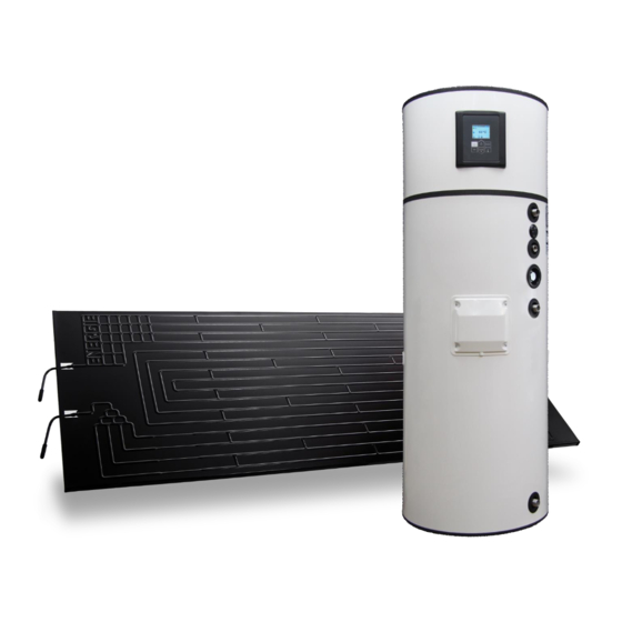
Technical Manual ECOTOP 3.3.4 Thermodynamic Solar Panel The thermodynamic solar panel, responsible for the process of evaporation of the fluid, is made of aluminium, with post-pressing anodic oxidation that gives it a black appearance. There are two types of panels: left and right (designated by the connection side): Left Panel Right Panel The panels have the following pipe diameters:... -
Page 18: Thermodynamic Block + Cylinder
Technical Manual ECOTOP 3.3.5 Thermodynamic Block + Cylinder Thermodynamic Block The thermodynamic group, located at the top of the equipment, includes some fundamental components for the operation of the thermodynamic cycle, namely, the compressor and the expansion valve. At the rear of the equipment there are 2 and 3-way valves for connection to the panel: Equipment with a thermodynamic panel: 3/8 ’’... -
Page 19: Refrigerant
Technical Manual ECOTOP 3.3.6 Refrigerant R134a is an HFC refrigerant, and as such, it is not harmful to the ozone layer. They have great thermal and chemical stability, low toxicity, are not flammable and are compatible with most materials. The following table lists the evaporation temperature with the pressure: T (ºC) P (bar) -
Page 20: Safety Group
Technical Manual ECOTOP 3.4.5 Safety Group The safety device allows the system to be protected against anomaly situations: cold water supply, hot water flowing back, emptying of the storage water heater and high pressure. The valve is calibrated to activate at 0.7 MPa). To drain the water in the storage water heater, you should close the supply valve and open the discharge valve. -
Page 21: Installation
Technical Manual ECOTOP 4 INSTALLATION Assembly sequence: a) Thermodynamic solar panel fixing e) Electrical connections b) Placement of the cylinder + thermodynamic f) Nitrogen load block g) Leak verification c) Refrigerant connections h) Vacuum d) Hydraulic connections i) Installation start-up The unit is preloaded for a maximum connection length of up to 12 meters (horizontal) between the panel and the water heater. - Page 22 Technical Manual ECOTOP The system has 3 small profiles (side A) and 3 large profiles (side B) that must be fixed as shown in the image, giving the panel a desirable inclination. SIDE B SIDE A If the panel is to be installed in a climatic zone conducive to snowfall, the panel must be installed with a minimum slope of 45º! The profile must be fixed to the base (eg tile) using a plastic anchor and M6 screw provided.
-
Page 23: Positioning
Technical Manual ECOTOP 4.2 Positioning Preliminary considerations: • House and protect the equipment in places susceptible to ice formation; • Choose the position closest to the main points of use; • Always insulate the pipes; • The ambient temperature around the equipment must not exceed 40 ° C; •... -
Page 24: Connections To The Panel
Technical Manual ECOTOP 4.3.1 Connections to the panel 1 Panel a) Prepare the copper pipe, removing the protective caps from the extremities. b) Place the extremity of the pipe upside down, cut the appropriate size of pipe and sand the rough edge. -
Page 25: Connection Of Copper Tubes To Equipment
Technical Manual ECOTOP 4.3.2 Connection of copper tubes to equipment Some of the steps to be carried out are the repetition of the procedures carried out in connection to the panel. a) Cut the tube to the required size with the end facing down. Clean existing burrs; b) Taper the tube, not forgetting to place the female on the side of the tube;... -
Page 26: Load Of Nitrogen
Technical Manual ECOTOP 3-Way-Valve 2-Way-Valve Pressure intake Conic nut Valve socket Liquid line (small diameter) Valve needle Gas line (large diameter) Hexagonal tip wrench (Allen Key) All connections must be isolated! 4.3.3 Load of Nitrogen a) After finishing the couplings, make sure there are no leaks. For this purpose, inject a load of nitrogen with a pressure of 10 bar through the pressure inlet (3-way valve). -
Page 27: Vacuum
Technical Manual ECOTOP 4.3.4 Vacuum a) During the whole procedure, employ, connections, vacuum pump and pressure gauges suitable for fluid R134a. b) Employ a vacuum pump only to remove the air and humidity inside the piping. c) Never use the system coolant to purge the connection pipes. d) The valves must be completely shut during the vacuum process, in order to create vacuum only in the piping. -
Page 28: Checking Good Running Condition
Technical Manual ECOTOP 4.3.5 Checking good running condition To check whether your equipment is running correctly, start it and wait at least 30 minutes and then check these conditions: a) Super-heating, without solar radiation directly over the panel, should be within the range 5ºC to 10ºC (Super-heating = Tsuction - Tevaporation);... -
Page 29: Electrical Connections
Technical Manual ECOTOP To assemble the couplings of the hydraulic circuit you must: a) Connect the water inlet and outlet of the equipment with a pipe and fittings that can cope with constant temperature / pressure of 75 ºC / 7 bar. For this reason, we recommend the use of piping with resistance to high temperature and pressure. -
Page 30: Wiring Diagram
Technical Manual ECOTOP 4.5.1 Wiring diagram Temperature probe Running condenser Comp Compressor Compressor fuse Low pressure switch Main fuse Support electrical heater Neutral Solenoid Valve Phase Safety thermostat... -
Page 31: First Use
Technical Manual ECOTOP 5 FIRST USE 5.1 Filling the Tank a) Open a cold water tap / isolation valve next to the safety group (this procedure is also used to check if the drain valve is closed); b) After obtaining flow in the hot water tap(s), shut it. Your water heater is full; c) Check the tightening in the pipes;... -
Page 32: Keys (Functions)
Technical Manual ECOTOP 6.2 Keys (Functions) Function Description (ON/OFF) Switch Switch on and off controller ON/OFF on/off CANCEL ESC function to exit menu, submenu or cancel a function. (CANCEL ) Exit (OK) Confirmation Confirm parameters within menus or submenus OK / (LOCK ) Lock/ Unlock Lock or unlock keyboard MENU... -
Page 33: Operating Modes
Technical Manual ECOTOP 6.4 Operating Modes ECOTOP is programmed to work in 3 running modes, ECO, AUTO and BOOST, which are summarized in this table: Mode Symbols Operation Normal running as Thermodynamic System Optimized management of running of Thermodynamic System and/or AUTO Electrical Resistance (support) BOOST... -
Page 34: Extra Modes
Technical Manual ECOTOP 6.5 Extra Modes 6.5.1 DISINFECT Function The ECOTOP electronic control features the Disinfect function, which consists of a water heating cycle up to 65 °C, for a period of time long enough to prevent the formation of germs inside the tank. -
Page 35: Errors
Technical Manual ECOTOP 7 ERRORS Symbols Description Problem / Checking Anomaly Er01 – S1 detected in probe Damaged probe - Measure the probe's internal resistance which at a temperature of 25ºC is approximately 10 KΩ. Anomaly Probe disconnected from the controller - Check that the detected connector is securely connected to the electronic board Er02 –... -
Page 36: Parameters Description
Technical Manual ECOTOP 8 PARAMETERS DESCRIPTION Values Code Type Parameters / Description Min Max Default Português; English; Français; Deutsche; Español; F01 Language English Italiano; F02 Clock Date and Time Week Chrono Heat Weekend Chrono OFF Pump ON/ OFF chrono Chrono Week Recirculation Weekend... -
Page 37: Probe Chart
Technical Manual ECOTOP 9 PROBE CHART 10 TROUBLESHOOTING Problem Possible causes How to proceed Check the power supply Power supply failure Failure in Check the corresponding circuit breaker Check the integrity of the electronic board’s electronic board Cable damaged or disconnected electric circuit Equipment is switched OFF Press the key ON/OFF. -
Page 38: System Maintenance
Technical Manual ECOTOP Problem Possible causes How to proceed Water is too hot Problem with the probe. Check error display on electronic board. and/or there is Problem with the thermostat. Check correct running of thermostat. steam The running of the equipment depends Outside temperature is very low on weather conditions. -
Page 39: Filter Of Reduction Valve
Technical Manual ECOTOP 11.2 Filter of Reduction Valve To periodically clean the filter of the reduction valve, you should: a) Shut off the water supply; b) Turn anti-clockwise until you remove tension from the spring; c) Remove the handle; d) Remove filter and clean. 11.3 Safety Thermostat The safety thermostat is disarmed whenever there is an anomaly in the system, so, whenever you want to rearm it, find out what happened for it to have acted. -
Page 40: Empty The Water Storage
Technical Manual ECOTOP 11.4 Empty the Water Storage Remember that the water in the storage water heater is at a high temperature, so there is an associated risk of burns. Before emptying the storage water heater, allow the water temperature to WARNING drop to a level that avoids burns. - Page 44 NOTE: This sheet must be properly filled, signed and stamped by the installer / reseller and returned to ENERGIE EST, Lda., otherwise the warranty will not be validated. Send this installation sheet to warranty@energie.pt, writing the serial number of the equipment as subject.
- Page 46 NOTES:...
Need help?
Do you have a question about the ECOTOP 200i and is the answer not in the manual?
Questions and answers