Table of Contents
Advertisement
Quick Links
Advertisement
Table of Contents

Related Manuals for clare ClareVision

Summary of Contents for clare ClareVision
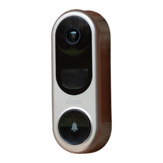
- Page 1 ClareVision Video Surveillance ClareVision Smart Video Doorbell Quick Start Guide...
-
Page 2: What's In The Box
WHAT’S IN THE BOX Mounting Plate X3 Use a wall stando or angled plate for Doorbell X1 adjusting the viewing Faceplate X3 angle. Pick the faceplate that matches best Plate Foam X1 for your installation. Use the foam plate to stabilize the Video Doorbell when installed on an uneven surface. -
Page 3: Tools You May Need
Wire Connectors (x4) Mounting Screws (x3) Anchors (x3) Security Screw (x1) Wire Terminal Screws (x2) TOOLS YOU MAY NEED Not included in the package. Drill Pencil NOTE • Install the Power Kit if using a mechanical or digital chime. • If no chime is installed, skip the Power Kit installation. •... - Page 4 POWER KIT INSTALLATION Shut o the electricity at the Insert one end of the wire breaker that controls the harness into the power kit. doorbell’s circuit. Remove the existing chime wires Remove the cover from your from the terminals mechanical chime. named TRANS and FRONT.
- Page 5 Connect the wire harness to the Insert the existing chime wire and chime’s terminals the other end of the wire harness named TRANS and FRONT. into the wire connector, and twist it tightly. Repeat this step with the other chime wire. Wire Connectors Chime Wire...
-
Page 6: Wiring Overview
Wiring Overview REAR TRANS FRONT Doorbell Installation Shut o the electricity at the (Optional) If the wall is uneven, breaker that controls the attach the plate foam to the doorbell’s circuit. mounting plate. NOTE • Recommended Installation Height: 4ft (1.2m) above the ground. - Page 7 Mark the drill points with a Drill holes according to the drill pencil. points, and insert anchors. Anchor A x the mounting plate to the Remove the faceplate cover. wall. Mounting Screw reset NOTE • Recommended Hole Depth: 1-1.5in (25-30mm).
- Page 8 Using wire nuts connect U-shaped wires to existing doorbell wires, then connect U-connectors to doorbell using Wire Terminal Screws. Wire Terminal Screws U-Shaped Wire Power Supply: 12 to 30 VAC Insert the mounting pegs on the back of the Video Doorbell into the mounting plate and slide down.
- Page 9 Insert and fasten Security Screw to lock doorbell to mounting plate. Restore the electricity at the breaker. NOTE • The Video Doorbell is powered on when the LED indicator ring around the call button is illuminated. If not, make sure your electricity is o and check the wiring.
- Page 10 Wait until the LED light ashes blue, indicating the reset is complete. You will hear the voice prompt say, “The doorbell is ready to connect to WiFi. ” Download and install the ClareVision app from the google Play or Apple App store to your device.
- Page 11 Launch the ClareVision app. On the Home screen, tap the menu dropdown and select the plus icon to Add Device. Select “Doorbell“ and tap “Device is NOT on a network”.
- Page 12 WiFi/Device password located on the back of the video doorbell and Quick Start Guide. Return to the ClareVision app. “Connected to device successfully” will display, tap Next. Verify Video Doorbell’s UDID, password, and edit the Device Name if desired. Tap Next.
- Page 13 No Chime: There is no doorbell chime connected to the video doorbell. Mechanical Chime: Traditional doorbell chimes that commonly make a ding-dong sound. Digital Chime: Doorbell chime that plays a unique digital tune. After completing setup using the ClareVision App, place the doorbell faceplate on the device.
-
Page 14: Led Indicator
Appendix Basics Reset Button Terminals MicroSD Card Slot LED Indicator Solid red Doorbell is powering on Flashing red Memory card exception Solid blue Doorbell is working Doorbell is ready for Wi-Fi con guration Flashing blue Network exception Flashing red & blue NOTE •... -
Page 15: Sd Card Management
SD Card Management In the Clare Vision app, tap the SD Card Information in the Device Settings interface to check the SD card status. If the card status displays as Uninitialized, tap to initialize it. The status will then change to Normal, and it can store videos and/or...
Need help?
Do you have a question about the ClareVision and is the answer not in the manual?
Questions and answers