Table of Contents
Advertisement
Quick Links
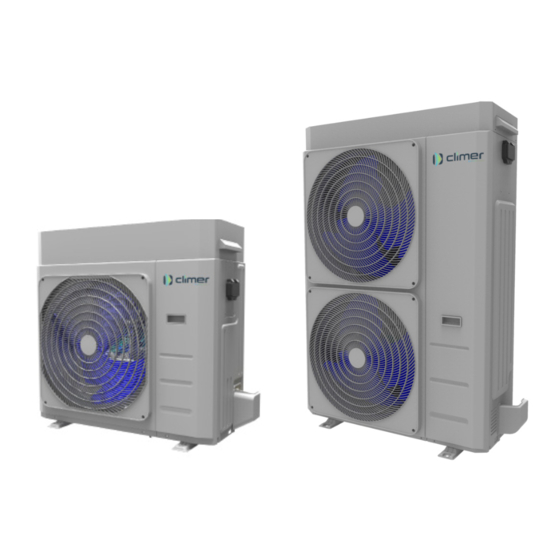
Air/Water heat pumps with axial fans
User-Installer Manual
Model
ACP06
ACP12
ACP08
ACP12T
This manual has been created for informative purpose. The company declines any responsibility for the results of any projecting or any installation based on the explanations and/or on the technical
specifications provided in this manual. It is besides forbidden the reproduction under any form of the texts of the figures contained in this manual. This manual is a translation from the official Spanish
language version. For reasons of environmental respect the Company will not provide the hard copy in the original language which could be directly requested or downloaded from the Company
website at any time. In case of any dispute, the original language manual will be the trusted one. Even partial reproduction PROHIBITED ©
www.climertechnology.com
ACP14
ACP14T
R32
Advertisement
Table of Contents

Related Manuals for Climer ACP06


Summary of Contents for Climer ACP06
- Page 1 Air/Water heat pumps with axial fans User-Installer Manual Model ACP06 ACP12 ACP14 ACP08 ACP12T ACP14T This manual has been created for informative purpose. The company declines any responsibility for the results of any projecting or any installation based on the explanations and/or on the technical specifications provided in this manual.
- Page 2 Air/Water heat pumps wih axial fans...
-
Page 3: Table Of Contents
Air/water inverter heat pumps with axial fansi Contents 1. PURPOSE AND CONTENTS OF THE MANUAL ..............5 1.1 HOW TO KEEP THE MANUAL ..................5 1.2 GRAPHIC SYMBOLS USED IN THE MANUAL ............5 2. NORMATIVE REFERENCES ....................5 3. PERMITTED USE ....................... 6 4. - Page 4 Air/Water heat pumps wih axial fans 5.9.4 Control logics ......................27 5.9.5 Fuses ........................27 6. STARTUP ......................... 27 6.1 SWITCHING ON THE UNIT ..................27 7. INSTRUCTIONS FOR THE USER ..................27 8. SHUTDOWNS FOR LONG PERIODS ................27 9. MAINTENANCE AND PERIODIC CHECKS ..............28 9.1 CLEANING THE FINNED COIL ..................
-
Page 5: Purpose And Contents Of The Manual
Air/water inverter heat pumps with axial fansi The manual of the ACP units, contains all the necessary information for optimal use of the equipment under safe conditions for the operator. 1. PURPOSE AND CONTENTS OF THE MANUAL This manual provides basic information as to the selection, installation, operation and maintenance of the ACP unit. It is intended for the opera- tors of the appliance and it enables them to use the equipment efficiently, even if they do not have any previous specific knowledge. -
Page 6: Permitted Use
Air/Water heat pumps wih axial fans 3. PERMITTED USE • The company excludes any contractual and extra contractual liability for damage caused to persons, animals or objects, by incorrect instal- lation, setting and maintenance, improper use of the equipment, and the partial or superficial reading of the information contained in this manual. -
Page 7: Workers' Health And Safety
Air/water inverter heat pumps with axial fansi Any routine or extraordinary maintenance operation must be carried out with the machine stopped and disconnected. Do not place your hands or introduce screwdrivers, spanners or any other tools on moving parts. The machine operator and maintenance personnel must receive suitable training for the performance of their tasks in safety. Operators must know how to use personal protective equipment and the accident-prevention rules of national and interna- tional laws and regulations. -
Page 8: Personal Protective Equipment
Air/Water heat pumps wih axial fans 4.2 PERSONAL PROTECTIVE EQUIPMENT Personal protective equipment must be used when operating and mainteining the units, such as: Clothing: Maintenance technicians and operators must wear protective clothing that does not leave parts of the body uncovered, as during maintenance it is possible to come into contact with hot or sharp surfaces. -
Page 9: Refrigeratn Safety Data Sheet
Air/water inverter heat pumps with axial fansi 4.4 REFRIGERATN SAFETY DATA SHEET Name: HAZARDS IDENTIFICATION Main hazards: Asphyxiati on. Specifi c hazards: Quick evaporati on could cause it to freeze. FIRST AID MEASURES General informati on: Do not administer to people who are unconscious. Immediately remove to fresh air. -
Page 10: Specific R32 Gas Warnings
Air/Water heat pumps wih axial fans 4.5 SPECIFIC R32 GAS WARNINGS The R32 refrigerant gas: • is odourless; • is flammable, but only if there are naked flames; • it may cause an explosion, but only if a given concentration in air is reached. It is good practice to follow these guidelines: •... -
Page 11: Transport And Storage Temperature Limits
Air/water inverter heat pumps with axial fansi All the maintenance operations and tests must be done by QUALIFIED PERSONNEL only. Before any operation on the unit, make sure that power is disconnected. Do not use equipment to speed up the defrost process or for cleaning except for those recommended by the manufacturer The appliance must be placed in a room without ignition sources constantly running (for example naked flames, a running gas-fired appliance or a running electric heater) Do not perforate or burn... -
Page 12: Positioning And Minimum Technical Clearances
It is very important to avoid recirculation between intake and delivery air, so as not to downgrade performance of the unit or even to interrupt its normal operation. This is why the minimum clearances shown below must be strictly guaranteed. Model ACP06 1500 ACP08 1500... - Page 13 Air/water inverter heat pumps with axial fansi Model ACP06 ACP08 ACP12 / ACP12T ACP14 / ACP14T Do not obstruct or cover the vents on the top cover. For strong wind installation place refer to the classification of the area according to the Beaufort table. If the value is > 7 (strong wind, average wind speed = 13, 9-17, 1 m/s) it is strictly necessary to keep the fan always powered, thus preventing involuntary rotation of the same.
- Page 14 Air/Water heat pumps wih axial fans In the event of winds stronger than 2.2 m/s the use of wind barriers is recommended. It is recommended to make an environmental impact valutation according to the power and sound pressure data reported in the technical data chapter and the sound emission limits according to the installation area of the unit, with reference to the DPCM of 14/11/1997.
-
Page 15: Dimensions
Air/water inverter heat pumps with axial fansi 5.5 DIMENSIONS 5.5.1 Model ACP 06 / 08 IN/OUT: 1"M G E: Power supply input 5.5.2 Model ACP 12 / 12T IN/OUT: 1"M G E: power supply input 1047... -
Page 16: Model Acp 14 / 14T
Air/Water heat pumps wih axial fans 5.5.3 Model ACP 14 / 14T IN/OUT: 1”M G E: power supply input 237 66145 1044 5.6 ACCESSING THE INNER PARTS 5.6.1 Model ACP 06 / 08... -
Page 17: Model Acp 12 / 12T
Air/water inverter heat pumps with axial fansi 1. Remove the cover 2. Uscrew the screws (number 2; 3; 4) of the sheet metal cover of the user interface and the screw (number 1) of the side panel to separate the front sheet metal from the side panel (Detail A). 3. Unscrew in sequence the screws (number 5;... -
Page 18: Plumbing Connections
Air/Water heat pumps wih axial fans 5.7 PLUMBING CONNECTIONS The plumbing connections must be made in accordance with national and/or local regulations; pipes can be made of steel, galvanised steel or PVC. Pipes must be accurately sized according to the nominal water flow rate of the unit and the pressure drops of the water circuit. All pipes must be insulated with closed-cell material of adequate thickness. -
Page 19: Typical Plumbing Diagram
Air/water inverter heat pumps with axial fansi 5.7.2 Typical plumbing diagram A recommended connection diagram is shown bellow. to sanitary users from water supply Sanitary probe secondary pump to radiant panel to fancoil from fancoil Remote plant probe Glycol fill 5.7.3 Condensation discharge system All units are built in such a way that the base of the unit acts as a condensate drip tray. -
Page 20: Discharge Of The Plant
Air/Water heat pumps wih axial fans 5.7.5 Discharge of the plant If the unit needs to be drained completely, first close the manual inlet and outlet gate valves (not included in supply) and then detach the pipes on the outside of the water inlet and outlet to drain liquid from the unit (to make this operation easier, it is recommended to install two drain valves between the unit and manual gate valves on the outside of the water inlet and outlet). -
Page 21: Functional Diagrams
Air/water inverter heat pumps with axial fansi 5.8 FUNCTIONAL DIAGRAMS 5.8.1 ACP 06 / 08 MAF1 EXT1 RD/RS CO/EV1 Y4W1 TRH1 PSH1 EEV1 INVC1 TRL1 KAS1 RS/RD EV/CO1 OUT1 LEGEND CODE NUM. DESCRIPTION CODE NUM. DESCRIPTION INVC VARIABLE SPEED COMPRESSOR W-OUT WATER SYSTEM OUTLET LINE CO/EV CONDENSER (IN CHILLER MODE) W-IN... -
Page 22: Acp 12 / 12T
Air/Water heat pumps wih axial fans 5.8.2 ACP 12 / 12T MAF1 EXT1 RD/RS CO/EV1 Y4W1 TRH1 PSH1 EEV1 INVC1 TRL1 KAS1 RS/RD EV/CO1 OUT1 LEGEND CODE NUM. DESCRIPTION CODE NUM. DESCRIPTION INVC VARIABLE SPEED COMPRESSOR W-OUT WATER SYSTEM OUTLET LINE CO/EV CONDENSER (IN CHILLER MODE) W-IN... -
Page 23: Acp 14 / 14T
Air/water inverter heat pumps with axial fansi 5.8.3 ACP 14 / 14T MAF1 EXT1 RD/RS21 CO/EV1 RD/RS MAF1 RL21 Y4W1 RD/RS22 CO/EV1 TRH1 RL21 PSH1 EEV1 INVC1 TRL1 KAS1 RS/RD EV/CO1 OUT1 LEGEND CODE NUM. DESCRIPTION CODE NUM. DESCRIPTION INVC VARIABLE SPEED COMPRESSOR W-OUT WATER SYSTEM OUTLET LINE CO/EV... -
Page 24: Electrical Connections
Air/Water heat pumps wih axial fans 5.9 ELECTRICAL CONNECTIONS Check that the power supply matches the unit’s electric nominal data (voltage, phases, frequency) displayed on the rating plate on the unit’s side panel. The electric power connections must be made in accordance to the wiring diagram enclosed with the unit and in conformity with national and international standards (providing general circuit breaker, residual current devices for each line, proper earthing of the plant, etc.). -
Page 25: User Terminal Block
Recommended tightening torque Model (max lenght 30 m) L/N: 3,4 Nm – PE: 1 Nm 230V / 1ph ACP06 / ACP08 3 x 4 mm² L/N: 3,4 Nm – PE: 1 Nm 230V / 1ph ACP12 3 x 4 mm²... - Page 26 Air/Water heat pumps wih axial fans TERMINAL CONNECTION TYPE Remote on/off input X-15.1/X15.2 Voltage-free digital input (closed=machine on / open=machine off) Terminal board 06/08/12/14 (1ph) X-1.1 X-22.1 X-20.1 X-19.1 X-17.1 X-15.1 X-16.1 X-5.1 X-14.1 X-11.1 X-10.1 X-9.1 X-6.1 X12-2 X12-1 X-22.2 X-20.2 X-19.2...
-
Page 27: Control Logics
Air/water inverter heat pumps with axial fansi 5.9.4 Control logics For the control logics, see the controller manual. 5.9.5 Fuses Details on the type and nominal specifications of the fuses are set out on the machine’s data plate, on electrical schemes and on the fuses themselves. -
Page 28: Maintenance And Periodic Checks
Air/Water heat pumps wih axial fans The anti-freeze system remains in operation if the continuity of electrical supply to the appliances is guaranteed. If the system is expected to remain idle for a long period, it is recommended to empty the liquid from the system unless there is an adequate amount of glycol. -
Page 29: Cleaning The Finned Coil
Air/water inverter heat pumps with axial fansi The following are the recommended and mandatory activities for correct operation of the unit. The mandatory activities must be carried out by an authorised customer service which issues a corresponding certificate. Failure to comply with these activities will entail forfeiture of the warranty and could considerably shorten the service life of your product. -
Page 30: Cleaning Of External Surfaces
Air/Water heat pumps wih axial fans CAUTION: Do not clean the coil using high-pressure cleaners so as not to apply excessive pressure which could cause irrepa- rable damage. Damage caused by cleaning with unsuitable chemical substances or excessively high water pressure will not be recognised under warranty. -
Page 31: Residual Risks
Air/water inverter heat pumps with axial fansi 10.1 RESIDUAL RISKS This paragraph sets forth any residual risks which cannot be eliminated by the manufacturer in the design stage. Precautions/Corrections Risk due to: There is always the risk of the unit falling or tipping over during handling. Follow the instructions in the “Handling” Handling section and take all of the precautions foreseen according to local regulations. - Page 32 Air/Water heat pumps wih axial fans Completed Measure Notes Checking the refrigeration system • Any replacement electrical components must be suitable for the applica- tion and must correspond to the manufacturer’s specifi- cation. Only replace faulty components with genuine spare parts. •...
- Page 33 Air/water inverter heat pumps with axial fansi Completed Measure Notes Refrigerant detection • On no account use possible sources of ignition for refrigerant detection or leak detection. • Flame leak detectors or other detectors with open flames must not be used. Leak detection The following leak detection processes are suitable for systems with flammable refrigerants:...
- Page 34 Air/Water heat pumps wih axial fans Completed Measure Notes Decommissioning Before carrying out this procedure, it is essential that the technician is completely familiar with the equipment and all its detail. It is recommended good practice that all refrigerants are recovered safely. Prior to the task being carried out, an oil and refrigerant sample shall be taken in case analysis is required prior to re-use of reclaimed refrigerant.
-
Page 35: Technical Data
Air/water inverter heat pumps with axial fansi TECHNICAL DATA 11.1 STANDARD UNIT TECHNICAL SHEET TECHNICAL SPECIFICATIONS Unit Cooling capacity (1) 3,22 / 5,19 / 5,71* 3,74 / 6,14 / 6,65* min/nom/max Input power (1) 1,64 1,97 E.E.R. (1) 3,16 3,12 Cooling capacity (2) 5,52 / 6,37 / 6,72* 5,58 / 8,03 / 8,67* Cooling... - Page 36 Air/Water heat pumps wih axial fans TECHNICAL SPECIFICATIONS Unit Cooling capacity (1) 4,55 / 8,51 / 9,36* 4,55 / 8,51 / 9,36* min/nom/max Input power (1) 2,79 2,79 E.E.R. (1) 3,05 3,05 Cooling capacity (2) 6,41 / 11,6 / 12,8* 6,41 / 11,6 / 12,8* min/nom/max Cooling...
- Page 37 Air/water inverter heat pumps with axial fansi TECHNICAL SPECIFICATIONS Unit Cooling capacity (1) 6,87 / 11,5 / 12,1* 6,87 / 11,5 / 12,1* min/nom/max Input power (1) 3,53 3,53 E.E.R. (1) 3,25 3,25 Cooling capacity (2) 9,17 / 14,0 / 14,7* 9,17 / 14,0 / 14,7* min/nom/max Cooling...
-
Page 38: Unit And Auxiliary Electrical Data
Air/Water heat pumps wih axial fans Performance referring to the following conditions, according to standard 14511:2018: (1) Cooling: outdoor air temperature 35°C; in/out water temperature 12/7°C. (2) Cooling: outdoor air temperature 35°C; in/out water temperature 23/18°C. (3) Heating: outdoor air temperature 7°C db 6°C db; in/out water temp 30/35°C. (4) Heating: outdoor air temperature 7°C db 6°C db;... -
Page 39: Ambient Air Temperature And Summerised Table
Air/water inverter heat pumps with axial fansi 12.4 AMBIENT AIR TEMPERATURE AND SUMMERISED TABLE The units are designed and built to operate in summer mode, with condensation control, at outdoor air temperatures between -10°C and +46°C. In heat pump mode, the allowed temperature range of the outdoor air is from -20°C to 40°C depending on the outlet water temperature as shown in the table below. - Page 40 Air/Water heat pumps wih axial fans COOLING MODE ACP Cooling -20,0 -10,0 10,0 20,0 30,0 40,0 50,0 Ta [°C] DOMESTIC HOT WATER MODE ACP sanitary mode -40,0 -30,0 -20,0 -10,0 10,0 20,0 30,0 40,0 50,0 Ta [°C]...
-
Page 41: User Interface - Controller
Air/water inverter heat pumps with axial fansi USER INTERFACE - CONTROLLER The unit is complete with a display located under a transparent hinged polycarbonate door with IP67 protection rating. The interface consists of a variable text part and a series of icons identifying the operation of the unit as shown in the table below. Cooling mode led: led ON if unit is in COOL or COOL+SAN mode. -
Page 42: Menu
Air/Water heat pumps wih axial fans In standard operation, the display shows the water outlet temperature in tenths of Celsius degrees or the alarm code if at least one is active. If several alarms are triggered, the first one is displayed while the second one will be displayed as soon as the first one is reset. In menu mode, the display depends on the current position. - Page 43 Air/water inverter heat pumps with axial fansi...
- Page 44 CLIMER TECHNOLOGY Ctra. N-331 Córdoba -Málaga km.77 14900 Lucena (Córdoba) España Tel. (+34) 957 89 00 46 E-mail: climer@climer.es www.climertechnology.com...
Need help?
Do you have a question about the ACP06 and is the answer not in the manual?
Questions and answers