
Related Manuals for LLG LLG-uniSPEC 2


Summary of Contents for LLG LLG-uniSPEC 2
- Page 1 INSTRUCTION MANUAL ® L A B W A R E INSTRUCTION MANUAL LLG-uniSPEC 2 Please read the User Manual carefully before use, and follow all operating and safety instructions!
- Page 2 ® L A B W A R E 1. Preface 1. Safety ........3 2.
-
Page 3: Table Of Contents
INSTRUCTION MANUAL Quantitative......15 Kinetics ....... . . 21 Setup . - Page 4 ® ® L A B W A R E L A B W A R E 3. Electrical Before switching on the apparatus, make The protective action must not be negated sure it is set to the voltage of the local by the use of an extension cord without a power supply (see Installation).
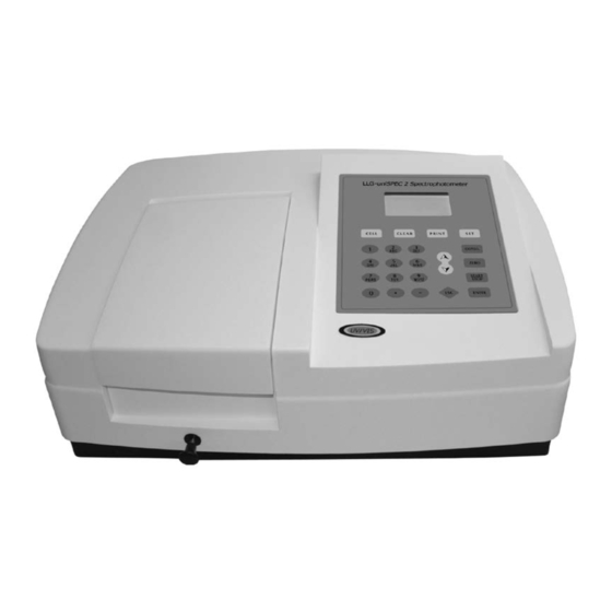
- Page 5 INSTRUCTION MANUAL 2. Introduction of the Instrument 1. Brief Introduction of the Instrument 1. Brief Introduction of the Instrument This This instrument incorporates a 128 x 64 dots instrument is a single beam, general purpose matrix LCD display for photometric results, instrument designed to meet the needs of easy operation and wavelength range of the Conventional Laboratory, This instrument...
- Page 6 ® L A B W A R E Fig Back View Air inlet Fuse Parallel port Power switch Power socket USB port 2. Working Principle Different matter has different but special Note: absorbance wavelength point. Also, when at When test, the solvent is usually taken as the fixed wavelength point, the absorbance the Reference Solution and its Transmittance has some relation to the substance’s (Always...
- Page 7 INSTRUCTION MANUAL 3. Structure The spectrophotometer consists of five 4. Detector to receive the transmitted light parts: and convert it to an electrical signal; and 1. Halogen or deuterium lamps to supply the A digital display to indicate absorbance or light transmittance.
- Page 8 ® L A B W A R E 5. Specifications Model LLG-uniSpec 2 Wavelength Range 190-1100 nm Band Width 2 nm Wavelength Accuracy ± 0.5 nm Wavelength Repeatability 0.3 nm Wavelength Setting Auto Photometric Accuracy ±0.5 % T Photometric Repeatability 0.3 % T...
- Page 9 INSTRUCTION MANUAL 3. Install Instrument 1. Environment Required To ensure the best performance, the • Remove any obstructions or materials following conditions are required: that could hinder the flow of air under and around the instrument. • The best working temperature range is 16-30 °C and the humidity is 45-80 %.
- Page 10 ® L A B W A R E 3. Installation Step 1: Check the packing list Step 4: Link the power cord Unpack the contents, check the materials Make sure the instrument’s power switch with the Packing List. Any damage or Lost is in the Off condition, link the power cord found, please contact us or the local dealer.
- Page 11 INSTRUCTION MANUAL 4. Operation Introduction 1. Software Structure 1.1 Menu Tree...
- Page 12 ® L A B W A R E 1.2 Firmware Functions The firmware consists of 4 functions: Basic Mode, Quantitative, Kinetics and System Functions. 1.2.1 Basic Mode 1.2.3 Kinetics Measure the Absorbance, Transmittance or Measure the absorbance or transmittance Energy in a fixed wavelength point. The test of a sample at a specific wavelength in a result can be stored in the RAM.
- Page 13 INSTRUCTION MANUAL 3. Preparation before test 3.1 Switch on the instrument and 3.2 Pre-warm begin the system self-test (Diagnostic When the diagnostic program finished, it Program) goes into pre-warm condition. 20 minutes is Make sure to remove all the blocks in the required before measure.
- Page 14 ® L A B W A R E Step 3: Set Photometric Mode Press to go into Parameter Setting Interface, press Array Key to select “Abs”, “%T” or “Energy” mode, press to confirm. Press to return. ENTER Basic Mode Basic Mode 0.000 Abs 500.0 nm Energy...
-
Page 15: Quantitative
INSTRUCTION MANUAL 4.2 Quantitative Step 1: Go into Basic Mode interface In the main menu, press Arrow Key to choose “Quantitative”; Press to enter the ENTER Quantitative method selecting Interface. ENTER Quantitative Basic Mode Quantitative Standard Curve Kinetics Coefficient Setup Unit Step 2: Choose Unit Move the cursor on “Unit”, press... - Page 16 ® L A B W A R E (2) Set Wavelength Move the cursor on “Create Curve”, then press to go into the Fit Method select ENTER interface. If you select “Linear Zero”, then the curve must go through the zero point. If you select “Linear Fit”, then it doesn’t necessarily go through zero point.* Fit Method ENTER...
- Page 17 INSTRUCTION MANUAL (4) Confirm the quantity of standard samples Use the numeric keypad or Arrow Key to input the quantity of the standard samples (e.g. There are 6 Standard Samples), then press to confirm. The system will go into the ENTER following interface.
- Page 18 ® L A B W A R E * Measure the other standard samples in the same way. When the last sample is finished, press to confirm. Then the Standard Curve and its equation will display on the screen ENTER automatically.
- Page 19 INSTRUCTION MANUAL * Move the cursor on the equation that you need and press to confirm. Then the ENTER corresponding curve will display on the screen. Curve Data ENTER * Press to go into sample continuous measure interface and measure samples. ENTER Note: When you reload the curves, the wavelength will be set at the point where you create the...
- Page 20 ® L A B W A R E II. Coefficient Method: (1) Go into “Coefficient” method. Press Arrow Key to choose “Coefficient”, press to go into pre-test interface, then press ENTER to go into the parameter setting interface. Standard Curve Coefficient Standard Curve ENTER...
-
Page 21: Kinetics
INSTRUCTION MANUAL (4) Calibrate 100 %T/0Abs Press to go into continuous measurement interface. Pull the Reference Solution in the START STOP light path, then press to calibrate 100 %T/0Abs. ZERO START Coefficient STOP 0.000 Abs Abs. MG/ml 0.000 mg/ml 500.0 nm (5) Measurement Place the samples to be measured in the light path, press to measure, then the result... - Page 22 ® L A B W A R E Step 2: Set parameters Press to enter Kinetics setting interface, you can set test mode, kinetics time (Total Time), and the display range of Y-axis (Top Limit and Bottom). You can also browse the test data after completing the measurement by selecting “Record List”.
- Page 23 INSTRUCTION MANUAL * Test time Setting Press Arrow Key to select “Total Time” in Kinetics setting interface and press to go into ENTER the setting interface. Input the time and press to confirm. ENTER Kinetics Kinetics ENTER Total Time Bottom 180S Total Time Record List...
-
Page 24: Setup
® L A B W A R E Step 5 Check the Test Data When the kinetics measurement finished, you can select Record List to check all the data. Kinetics ENTER Bottom Total Time Record List 4.4 SET UP In the main menu, press Arrow Key to choose “Setup” and press to go into utility ENTER setting interface. -
Page 25: Power On/Off W Lamp
INSTRUCTION MANUAL 4.4.2 Power on/off W Lamp When the wavelength point needed is in the range of 190-339 nm, the W lamp can be switched off to prolong its life time. Use the key of Arrow Key to choose “W Lamp”, press to go into W lamp setting ENTER interface. -
Page 26: Calibrate Dark Current
® L A B W A R E 4.4.4 Calibrate Dark Current When the working condition changes, A dark current calibration is required before any measurement. Use Arrow key to choose “Dark Current” and press to confirm. ENTER Note: Remove the cuvettes from the light path before this action, don’t open the lid of the compartment during the course of calibration. -
Page 27: Input The Lamps Changing Wavelength Point
INSTRUCTION MANUAL 4.4.6 Lamps Change (Input the lamps changing wavelength point) The instrument permits the users to set the lamps changing wavelength point. In the range of 300-400nm, users can choose the lamp freely. Press Arrow Key to choose “Lamp Change” and press to go into corresponding setting ENTER interface. -
Page 28: Daily Maintenance
® L A B W A R E 4.4.8 Version Press Arrow Key to choose “Version” and press to confirm. You’ll see the version of the ENTER software and hardware. Press to return. ENTER Set Up Lamp Change Load Default Version 5. -
Page 29: Trouble Shooting
INSTRUCTION MANUAL 2. Troubleshooting 2.1 Dark Current Error when self-test Possible Cause Solution • Open the lid of the compartment during • Close the lid of the compartment and the course of self-test. switch on the power again. 2.2 No response after power on Possible Cause Solution •... -
Page 30: Spare Part Replacement
® L A B W A R E 3. Spare part replacement Replace the Fuse Danger! Be sure to switch off the power and unplug the socket before replacement! Step 3: Take out the Fuse Seat Step 1: Tools preparation Take out the fuse seat by the screwdriver. - Page 31 INSTRUCTION MANUAL WARRANTY REPLACEMENT This product is warranted to be free from defects in material and workmanship for a period of three (3) years from date of purchase. This warranty is valid only if the product is used for its intended purpose and within the guidelines specified in this instruction manual.
- Page 32 L A B W A R E L A B W A R E ® L A B W A R E Lab Logistics Group GmbH Am Hambuch 1 D-53340 Meckenheim/Deutschland Tel.: +49 (0)2225 9211- 0 Fax: +49 (0)2225 9211-11 www.llg-labware.com info@llg-labware.com...
Need help?
Do you have a question about the LLG-uniSPEC 2 and is the answer not in the manual?
Questions and answers