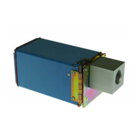
Honeywell C7076A Operating Instructions Manual
Adjustable sensitivity ultraviolet flame detector
Hide thumbs
Also See for C7076A:
- Instruction sheet (20 pages) ,
- Product handbook (34 pages) ,
- Product data (24 pages)
Table of Contents
Advertisement
Quick Links
C7076A adjustable sensitivity ultraviolet flame
detector
Contents
1 Safety . . . . . . . . . . . . . . . . . . . . . . . . . . . . . . . . . . . . . . . 1
2 Application . . . . . . . . . . . . . . . . . . . . . . . . . . . . . . . . . . . 2
3 Checking the usage . . . . . . . . . . . . . . . . . . . . . . . . . . . . 2
4 Features . . . . . . . . . . . . . . . . . . . . . . . . . . . . . . . . . . . . . 2
5 Technical data . . . . . . . . . . . . . . . . . . . . . . . . . . . . . . . . 2
6 Accessories . . . . . . . . . . . . . . . . . . . . . . . . . . . . . . . . . .3
7 Replacement parts . . . . . . . . . . . . . . . . . . . . . . . . . . . . .3
8 Installation . . . . . . . . . . . . . . . . . . . . . . . . . . . . . . . . . . .3
9 Installing the detector . . . . . . . . . . . . . . . . . . . . . . . . . . .5
10 Wiring . . . . . . . . . . . . . . . . . . . . . . . . . . . . . . . . . . . . . .6
11 Adjustments and checkout . . . . . . . . . . . . . . . . . . . . . .8
12 Sensitivity adjustments . . . . . . . . . . . . . . . . . . . . . . . . .9
13 Troubleshooting . . . . . . . . . . . . . . . . . . . . . . . . . . . . .10
14 Service and Maintenance . . . . . . . . . . . . . . . . . . . . . . 11
15 Certification. . . . . . . . . . . . . . . . . . . . . . . . . . . . . . . . .14
16 Disposal . . . . . . . . . . . . . . . . . . . . . . . . . . . . . . . . . . .14
oPeRAtInG InstRUCtIons
1 sAFetY
1.1 Please read and keep in a safe place
Please read through these instructions carefully before
installing or operating. Following the installation, pass the instructions
on to the operator. This unit must be installed and commissioned
in accordance with the regulations and standards in force. These
instructions can also be found at www.docuthek.com.
1.2 explanation of symbols
1 , 2 , 3 , a , b , c = Action
➔ = Instruction
1.3 Liability
We will not be held liable for damage resulting from non-observance
of the instructions and non-compliant use.
1.4 safety instructions
Information that is relevant for safety is indicated in the instructions
as follows:
DAnGeR
Indicates potentially fatal situations.
WARnInG
Indicates possible danger to life and limb.
CAUtIon
Indicates possible material damage.
All interventions may only be carried out by qualified gas techni-
cians. Electrical interventions may only be carried out by qualified
electricians.
1.5 Conversion, spare parts
All technical changes are prohibited. Only use OEM spare parts.
· Edition 08.22 · 95-8269 · EN
Advertisement
Table of Contents

Related Manuals for Honeywell C7076A


Summary of Contents for Honeywell C7076A
-
Page 1: Table Of Contents
C7076A adjustable sensitivity ultraviolet flame detector oPeRAtInG InstRUCtIons · Edition 08.22 · 95-8269 · EN 1 sAFetY 1.1 Please read and keep in a safe place Please read through these instructions carefully before installing or operating. Following the installation, pass the instructions on to the operator. -
Page 2: Application
R7886: One test every 5 seconds to provide self-checking. Pressure C7076A quartz viewing lens: 20 psig (138 kPa) maximum. Interchangeability Model C7076A is not interchangeable with other flame detector 1 Housing models; it must be used with the R7886 Dynamic Self-Check 2 Plug-in Electronic Chassis Ultraviolet Amplifier. -
Page 3: Accessories
8.5 single burner requirements ➔ For the C7076A, to keep the detector temperature within spec- The detector must have an unobstructed view of a steady part of ifications, the aspirator temperature must not exceed 225 °F the flame it is supervising. - Page 4 8.6 sighting angle The first 30% of a flame closest to the burner nozzle (the flame root) Flame B Flame A emits the most ultraviolet energy. Also, if the detector sights the flame Detector A Detector B at an angle instead of perpendicularly, it views more flame depth. Therefore, the best sighting angle is nearly parallel to the axis of the flame, permitting the detector to view a large portion of the first 30% of the flame closest to the burner nozzle.
-
Page 5: Installing The Detector
1 inch (25) – If an air supply is connected to the aspirator on the C7076A, diameter its pressure must equal or exceed that required to seal off the detector from the combustion chamber. -
Page 6: Wiring
– Use moisture-resistant no. 14 wire suitable for at least 167 °F (75 °C). – For High Temperature Installations, use Honeywell specification no. 32004766-003 or equivalent for the F leadwire. This wire is rated up to 480 °F (250 °C) for continuous duty. It is tested for operation up to 20,000 volts and for breakdown up to 35,000 volts. - Page 7 10.2 Connecting detectors in parallel Two C7076A flame detectors with the same voltage rating can be connected in parallel to the same terminals. To avoid exceeding the C7076A1031, rating of the shutter control circuit, do not connect more than two 220/240 V AC, 50/60 Hz detectors in parallel.
-
Page 8: Adjustments And Checkout
11.1 Flame signal readings The final sighting position of the C7076A detector may be most readily determined by using a test meter connected to the flame current meter jack on the plug-in electronics chassis. This output is... -
Page 9: Sensitivity Adjustments
12.2 single Burner system Using the C7076A Detector Flame 1 Loosen the four captive screws in the rear cover plate of the Current C7076A and remove the plate. -
Page 10: Troubleshooting
2 Microammeter with 0 to 25 µA range, SPL damping. frequency. Then trace the wiring between the detector and the 3 Meter connector plug (Honeywell part no. 117053 or equiva- main power supply to determine the problem. lent)—required for some meters. -
Page 11: Service And Maintenance
a If the shutter is not open, connect an AC voltmeter across termi- wired properly (no open circuits), replace the plug-in R7886 Dy- nals 3 and 4 on the terminal block. Make sure the AC voltage namic Self-Check Ultraviolet Amplifier. 6 If the previous actions have not corrected the problem, replace measured is within the voltage range listed in the previous table "Shutter voltage range". - Page 12 4 Gently push the alignment guide away from the tube until the tip 14.2 Replacing the Plug-In electronics chassis of the tube is free. 5 While holding the alignment guide away from the tube tip, grasp the tab on the tube bracket and swing the tube out from the chassis.
- Page 13 4 Cut the two white coil wires as close to the coil as possible. 14.5 Replacing the viewing lens 5 Remove the mounting screws from the base of the coil and shut- ter assembly. Replacing the lens 1 Front cover plate 2 Captive screws 3 Lens 4 Grommet small flange...
-
Page 14: Certification
R7886 flame amplifier. 15.2 sIL 3 Capable The C7076A when used with a R7886 self-check amplifier in Relay Module EC7810A, 20A, 30A, 40L, 50A; RM7800 [E,G,L,M], 30A, 38 [A,B,C], 40 [E,G,L,M] 50A, 90 [A,B,C,D], 97 [A,C], 98A is SIL 3 Capable in a properly designed Safety Instrumented System.
Need help?
Do you have a question about the C7076A and is the answer not in the manual?
Questions and answers