
Related Manuals for Kaysun KMC-32 E


Summary of Contents for Kaysun KMC-32 E
- Page 1 OWNER’ S MANUAL CENTRAL MONITOR CONTROL KMC-32 E Thank you very much for purchasing our product. Before using your unit, please read this manual carefully and keep it for future reference.
- Page 2 This manual gives detailed description of the precautions that should be brought to your attention during operation. In order to ensure correct service of the wired controller please read this manual carefully before using the unit. For convenience of future reference, keep this manual after reading it.
-
Page 3: Table Of Contents
CONTENTS 1. SAFETY PRECAUTION ................1 2. SUMMARIZE OF OUTDOOR KMC ............2 3. BASIC REQUIREMENTS ................3 4. OPERATION ....................3 5. INSTALLATION ..................10 6. TECHNICAL INDEX AND REQUIREMENT ..........11... -
Page 4: Safety Precaution
1. SAFETY PRECAUTIONS The following contents are stated on the product and the operation manual, including usage, precautions against personal harm and property loss, and the methods of using the product correctly and safely. After fully understanding the following contents (identifiers and icons), read the text body and observe the following rules. -
Page 5: Summarize Of Outdoor Kmc
Warning Please entrust the distributor or professionals to install the unit. The installers must have the relevant know-how. Delegate Improper installation performed by the user without installation Warning permission may cause fire, electric, shock, personal injury or water leakage. Do not spray flammable aerosol to the wire controller Forbid directly. -
Page 6: Basic Requirements
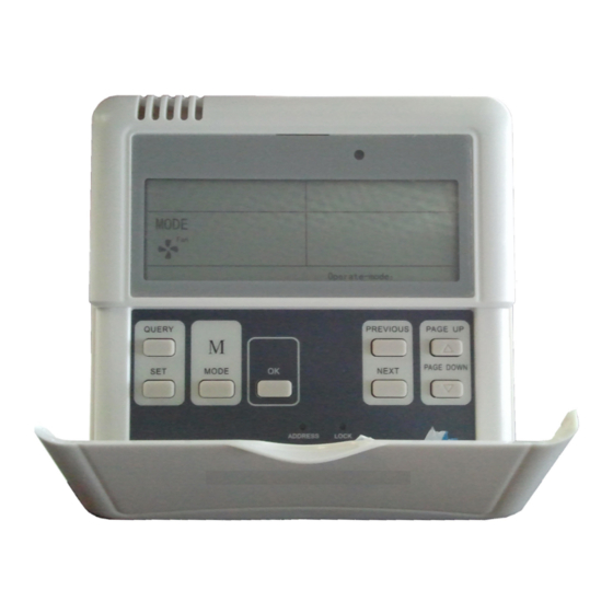
3. The KMC and outdoor units, PC and into normal display state, the KMC is in KMC adopt main-auxiliary responsion the main page and display the data in communication. In the network of KMC the first page. and outdoor units, KMC is the main unit Network Area Address Setting and outdoor units are the auxiliary units. - Page 7 Electric energy consumption query queried through KMC when the outdoor unit has its ammeter. The Electric energy consumption can be 4-2 Function 4-2-1 Buttons on KMC QUERY PREVIOUS PAGE UP NEXT PAGE DOWN MODE ADDRESS LOCK Graph 1 Button Distribution on KMC 1.
- Page 8 4. PAGE UP BUTTON Forced Cooling and OFF state. Pushing the PAGE UP button when 8. OK BUTTON choosing a online air-conditioner on the Pressing OK button to confirm all query state can display the parameters settings and send to the corresponding in previous page, and this can be cycled.
- Page 9 4-2-2 Datas Graph 2 LCD Screen OR display ' with the model: MD-KMC02/E(H) Common Display Data: communication 4.Press the OK button in setting page 1.Figure means KMC is sending and waiting for 4 seconds,"success"or query order; "fail" will be shown in the operation state 2.Figure means KMC is in area.;...
- Page 10 3.Stand-by Page can display the address 10.Page0 displays the consumption of KMC with the address format of "Addr of electric energy with: "ELECTRIC xx", here "xx" equals the real address ENERGY Kwh" and the number; of KMC plus 16, so the range of "xx" is 11.Page1 displays the input power 16-31.
- Page 11 18.Page8 displays the discharge malfunction with "MALFUNCTION" and temperature of compressor symboled the code; C3 ; 26.Page16 displays the most advanced 19.Page9 displays the compressor protection with "PROTECTION" and the current symboled 1 with"CURRENT A", code. "1" and the number; 20.Page10 displays the compressor NOTE...
- Page 12 air-conditioners. whether the transmission is confirmed or 5."successful"or "unsuccessfull" shown not. in the operation state area indicates 4-3 Malfunction and Protection Code Table ERROR Code ERROR Contents Description ERROR Code ERROR Contents Description Outdoor adding malfunction Defrost Protection (valid for host unit) Outdoor decreasing Compressor Current 3rd malfunction (valid for host...
-
Page 13: Installation
5. INSTALLATION 1. Never connect the network communication wire with strong power or put it into the same wiring tube with the strong power. And at least 300-500mm distance should be left between their wiring tubes. 2. The shield cable must be connected stable to the ground, or transmission may fail. 3. -
Page 14: Technical Index And Requirement
6. TECHNICAL INDEX AND REQUIREMENT EMC and EMI should conform to the requirement of CE Certification. - Page 15 Version: MDV06U-001IW 202000170150...
Need help?
Do you have a question about the KMC-32 E and is the answer not in the manual?
Questions and answers