Table of Contents
Advertisement
Quick Links
AirCraft
B-700, B-701B, B-731, B-750, B-751, B-781
®
AirGuard
Dryer Troubleshooting and Information Guide
All Bobrick dryers require cleaning every 6 months to ensure that
they function effectively. Please note that failing to clean the dryer
BOBRICK DOMESTIC
Email:
Corporate Office - Los Angeles - Bobrick Washroom Equipment
6901 Tujunga Avenue, North Hollywood, California 91605-6213
Customer Service: 818.982.9600, Fax: 818.503.9287
New York - Bobrick Washroom Equipment, Inc.
200 Commerce Drive, Clifton Park, New York 12065-1350
Customer Service: 518.877.7444, Fax: 518.877.5029
Canada - Bobrick Washroom Equipment Company
45 Rolark Drive, Scarborough, Ontario M1R 3B1
Customer Service: Eastern Canada: 877.423.6555, Fax: 423.765.8555
Western Canada: 877.423.6444, Fax: 423.503.8444
BOBRICK INTERNATIONAL
Email:
Corporate Office - Bobrick Washroom Equipment, Inc.
6901 Tujunga Avenue,, North Hollywood, California 91605-6213 USA
Customer Service: +1 818.764.1000, Fax: +1 818.503.9941
United Kingdom Bobrick Washroom Equipment Limited
Phone: +44 (0)20.8366.1771, Fax: +44 (0)20 8363 5794; Email:
Australia Bobrick Washroom Equipment Pty. Ltd.
Phone: +1800 353158, Fax: +1800 221926; Email:
B-708 & AirPro
®
may result in malfunction and can void the warranty.
customerservice@bobrick.com
international@bobrick.com
Effective 9/20/21
www.bobrick.com
australia@bobrick.com
B-709
®
uksales@bobrick.com
Advertisement
Table of Contents

Related Manuals for Bobrick AirCraft B-701B


Summary of Contents for Bobrick AirCraft B-701B
- Page 1 ® Dryer Troubleshooting and Information Guide Effective 9/20/21 All Bobrick dryers require cleaning every 6 months to ensure that they function effectively. Please note that failing to clean the dryer may result in malfunction and can void the warranty. www.bobrick.com...
-
Page 2: Table Of Contents
AirCraft B-700, B-701B, B-731, B-750, B-751, B-781 ® AirGuard B-708 & AirPro B-709 ® ® Contents Page Instructions for Using the Dryer Guide ..........3 Sample Dryer Service Information Sheet . -
Page 3: Instructions For Using The Dryer Guide
If the dryer still does not function after cleaning, then continue filling out the Dryer Service Information Sheet. • Inform the customer/end user that the malfunctioning/replaced parts must be returned to the Bobrick Customer Service Department or a charge will be made for replacement parts. -
Page 4: Sample Dryer Service Information Sheet
Repair kit/parts required (if dryer needs to be returned write RETURN): Return Part number(s) for replacements: Complete Unit Replaced on SO #: ________________ ANY DEFECTIVE PARTS MUST ACCOMPANY THIS COMPLETED SHEET TO BOBRICK’S SERVICE DEPARTMENT. Information sheet completed by: Your Name Completion Date:6/6/20 Branch/Rep Firm: _________________________________________________________ Form No. -
Page 5: Date Code Information
Date Code Information The date code on all Bobrick Dryers is found on the upper left corner of the rating label and on the serial number label. The date code will contain two digits and one letter. The digits designate the week and the letter designates the year. -
Page 6: Routine Maintenance Instructions
Should be cleaned with a damp cloth, DO NOT use aggressive cleaners or solvents as they may permanently damage the surface. Bobrick dryers are drip proof (IP21 or better, see rating label). DO NOT spray with liquids to an extent that they could enter the unit. -
Page 7: Product Identification
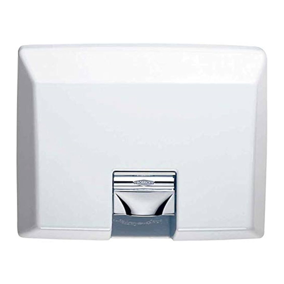
Product Identification AirCraft Dryers ® Surface-Mounted: B-700 Automatic Hand & Face (pictured) B-701 Touch Button Hand & Face B-731 Touch Button Hair Recessed: B-750 Automatic Hand & Face (pictured) B-751 Touch Button Hand & Face B-781 Touch Button Hair AirGuard Dryer ®... -
Page 8: Cover Removal
Instructions for Removal of Dryer Cover Warning Disconnect power Risk of electric supply before shock removing cover To Remove Cover Locate the two tamper resistant screws at the bottom of the dryer cover. Using the Allen-wrench (4 or 5mm), turn the screws clockwise to loosen the cover. Do not take the screws out, the screws have to be done up to loosen the cover. -
Page 9: Diagnostic Sheet
10. Dryer does not run and heating element glows Worn motor brushes Replace motor brushes; if still not functioning after replacing the motor brushes, return dryer to Bobrick for repairs. TOUCHBUTTON 1. Dryer does not run a) No electricity supply... -
Page 10: Screwdriver Test
Screwdriver Test for Touch Button Dryers Warning Disconnect power Risk of electric supply before shock removing cover NOTE: This test instruction sheet is not for dissemination to, and should not be disseminated to, the public including end users. This test is designed to test the Touch Timer Assembly and the Sensor Board. Instructions for Test: 1. -
Page 11: Field Replacement Parts
Field Replacement Parts • Replacement parts are intended to be issued by Bobrick after completion of diagnostic sheets and a problem is identified that involves replacement of parts. • Replacement parts will then be sold to the customer/rep with credit issued upon the return of identifiable malfunctioning and/or unused parts. -
Page 12: Aircraft ® Dryer B-700, B-701B, B-731 And B-750 Replacement Parts
AirCraft Dryer B-700, B-701B, B-731 and B-750 ® Replacement Parts SURFACE TOUCH SURFACE AUTOMATIC RECESSED TOUCH RECESSED AUTOMATIC 115V 208-240V 115V 208-240V 115V 208-240V 115V 208-240V TOUCH 701-360 701-361 701-360 701-361 CONTROLLER HAND & FACE TOUCH 731-360 731-361 731-360 731-361 CONTROLLER HAIR SENSOR BOARD... -
Page 13: Airguard ® B-708 & Airpro ® B-709 Dryer Replacement Parts
AirGuard B-708 & AirPro B-709 Dryer Replacement Parts ® ® 115V 208-240V TOUCH CONTROLLER 701-360 701-361 SENSOR BOARD 701-138 701-138 AUTOMATIC CONTROLLER 700-360 700-361 AIR OUTLET GRILLE & SEAL 701-120 701-120 B-708 SERIES A – F COVER 708-150 115V 708-150 230V B-708 SERIES G COVER 708G-150 115V 708G-150 230V... -
Page 14: Cover Replacement
Cover Replacement The dryer covers for different models are NOT interchangeable. Warning Disconnect power Risk of electric supply before shock removing cover Fig 1 Fig 2 Fig 2 Fig 1B Fig 1A To Remove Cover 1. Disconnect the power supply. 2. -
Page 15: Installation Of Touch Controller
Installation Of Touch Controller To Remove Existing Timer 1. Disconnect the power supply and remove the cover. 2. Remove the timer from the base plate by unscrewing the two screws securing the timer bracket to the base. On recessed dryers the timer bracket is secured to a metal angle bracket, this bracket with its screws must be removed and retained for use on the replacement timer. -
Page 16: Installation Of Base Plate Mounted Triac
Installation Of Base Plate Mounted Triac Note: This procedure applies only to surface-mounted or recessed dryers with triac mounted on the base plate. For touch button models with triac mounted on the timer bracket, the complete timer assembly must be replaced. Warning Disconnect power Risk of electric... -
Page 17: Installation Of Automatic Controller
Installation Of Automatic Controller Warning Disconnect power Risk of electric supply before shock removing cover Older units have an intermediate plug and socket in the wiring, this has now been discontinued and can be removed with the faulty controller. The wiring on older units may be sleeved, this was later replaced by plastic cable ties. Some early 115 volt dryers had 4 way terminal blocks instead of the current 3 way blocks, in these dryers the wires to the 4th terminal should not be disturbed. -
Page 18: Instructions For Installation Of Sensor Board
Instructions For Installation Of Sensor Board There are two methods fixing sensor boards. 1. Fixed with five screws, Fig 1. 2. Fixed with three screws, Fig 2. In both cases the orientation of the board is critical. Warning Disconnect power Risk of electric supply before shock... -
Page 19: Instructions For The Replacement Of Motor Brushes
Instructions For The Replacement Of Motor Brushes Warning Disconnect power Risk of electric supply before shock removing cover The brush spares kit contains two brushes. Always replace BOTH brushes. EMD MOTOR To remove the brush: 1. Squeeze the sides of the retainer and ease it over the stud with a small screwdriver. -
Page 20: Installation Of Surface-Mounted Hand Dryers
INSTALLATION INSTRUCTIONS BOBRICK SURFACE-MOUNTED HAND DRYERS ELECTRICAL CHARACTERISTICS. 115V AC, 20 Amp, 50/60 Hz, Single Phase, UL/c-UL listed. 208–240V AC, 9–10 Amp, 50/60 Hz, Single Phase, UL/c-UL listed, VDE approved. REMOVAL OF COVER Start installation of dryer by removing cover. To loosen two cover bolts insert Allen Wrench, provided with dryer, into holes located on bottom of cover on each side of air intake grille. - Page 21 Place mounting base on wall at the desired location of the installed dryer. See recommended mounting heights above. Use the mounting base or the template provided with dryer to mark location of four mounting screw holes and hole for electrical wiring if electrical supply is concealed in wall and will enter dryer from back through mounting base.
-
Page 22: Installation Of Recessed Aircraft ® Hand Dryers
INSTALLATION INSTRUCTIONS BOBRICK RECESSED AIRCRAFT B-709 HAND DRYERS ® ELECTRICAL CHARACTERISTICS. 115V AC, 20 Amp, 50/60 Hz, Single Phase, UL/c-UL listed. 208–240V AC, 9–10 Amp, 50/60 Hz, Single Phase, UL/c-UL listed, VDE approved INSTALLATION OF RECESSED MOUNTING BOX An Installation Template is supplied with each unit. - Page 23 Fasten recessed mounting box to framing with minimum of four No. 10 (4.8mm) sheet metal screws (not furnished by Bobrick). Make sure flanges of mounting box are completely flat against finished wall surface. If necessary, use shims or spacers between mounting box and framed wall opening to prevent distortion to box as it is fastened to framing.
-
Page 24: Schematic Diagrams
Schematic Diagram Schematic Diagram 115V Dryer 208-240V Automatic Dryer Schematic Diagram 208-240V Touch Dryer... - Page 25 Schematic Diagram QuietDry Dryers 115V 208-240V C - Cutout H – Heater M – Motor TS – Timer/Sensor...
-
Page 26: Warranty
Limited Warranty The Bobrick Dryer and all parts (except motor brushes) are warranted to the original owner of the installed unit for ten years from date of original installation for AirCraft B-700, B-701B, B-731, B-750, ® B-751, B-781 and AirGuard B-709 Automatic and Touch Button hand and hair dryers and five years ®...
Need help?
Do you have a question about the AirCraft B-701B and is the answer not in the manual?
Questions and answers