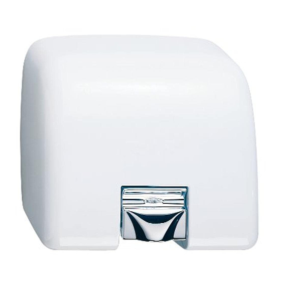
Bobrick AirCraft Series Troubleshooting And Information Manual

Bobrick AirCraft Series Troubleshooting And Information Manual

Advertisement

Dryer
Troubleshooting
and Information
Guide
Effective 2/08
www.bobrick.com
In the United States: BOBRICK WASHROOM EQUIPMENT, INC.
200 Commerce Drive, Clifton Park, NY 12065-1350, Telephone: (518) 877-7444, FAX: 518-877-5029
11611 Hart Street, North Hollywood, CA 91605-5882: (818) 982-9600, FAX: 818-503-1102
100 Bobrick Drive, Jackson, TN 38301-5635, Telephone: (731) 424-7000, FAX: 731-424-7800
In Canada: BOBRICK WASHROOM EQUIPMENT COMPANY.
45 Rolark Drive, Scarborough, Ontario M1R 3B1, Telephone: (416) 298-1611, FAX: 416-298-6351
International Sales: BOBRICK WASHROOM EQUIPMENT, INC.
11611 Hart Street, North Hollywood, CA 91605-5882, 818-764-1000, FAX: 818-503-9941.
Australia: Bobrick Washroom Equipment Pty Ltd., 1800-353158, FAX: 1800-221926. United Kingdom:
Bobrick Washroom Equipment Ltd., .,+44 (0)20 8366 1771, FAX: +44 (0)20 8363 5794. Germany: 00800 79
00 456, FAX: 00800 79 00 789. Other Countries: +1 (818) 764-1000, FAX: +1 (818)503-9941.
international@bobrick.com
Email:
Page 1

Advertisement

Table of Contents
loading
Need help?

Need help?

Do you have a question about the AirCraft Series and is the answer not in the manual?

Questions and answers

Subscribe to Our Youtube Channel

Summary of Contents for Bobrick AirCraft Series

  • Page 1 Australia: Bobrick Washroom Equipment Pty Ltd., 1800-353158, FAX: 1800-221926. United Kingdom: Bobrick Washroom Equipment Ltd., .,+44 (0)20 8366 1771, FAX: +44 (0)20 8363 5794. Germany: 00800 79 00 456, FAX: 00800 79 00 789. Other Countries: +1 (818) 764-1000, FAX: +1 (818)503-9941.
  • Page 2 Contents Page Instructions for Using the Dryer Guide Sample Dryer Service Information Sheet Date Code Information Routine Maintenance Instructions Links to model guides: ® AirCraft , AirGuard™ & AirPro Dryer™ Compac Dryer™ CubDryer™ ® EclipseDryer ElanDryer™ (International Sales Only) Page 2...
  • Page 3 Dryer Service Information Sheet.  Inform the customer/end user that the malfunctioning/replaced parts must be returned to the Bobrick Customer Service Department or a charge will be made for replacement parts. Page 3...
  • Page 4 Repair kit/parts required (if dryer needs to be returned write RETURN): __________________________________ Part number(s) for replacements: _____________________________ Replaced on SO #: ________________ ANY DEFECTIVE PARTS MUST ACCOMPANY THIS COMPLETED SHEET TO BOBRICK’S SERVICE DEPARTMENT. Information sheet completed by: ______________________________ Completion Date: __________________...
  • Page 5 Date Code Information The date code on all Bobrick Dryers is found on the upper left corner of the rating label and on the serial number label. The date code will contain two digits and one letter. The digits designate the week and the letter designates the year.
  • Page 6 Should be cleaned with a damp cloth, DO NOT use aggressive cleaners or solvents as they may permanently damage the surface. Bobrick dryers are drip proof (IP21 or better, see rating label). DO NOT spray with liquids to an extent that they could enter the unit.
  • Page 7 Australia: Bobrick Washroom Equipment Pty Ltd., 1800-353158, FAX: 1800-221926. United Kingdom: Bobrick Washroom Equipment Ltd.,+44 (0)20 8366 1771, FAX: +44 (0)20 8363 5794. Germany: 00800 79 00 456, FAX: 00800 79 00 789. Other Countries: +1 (818) 764-1000, FAX: +1 (818)503-9941.
  • Page 8: Table Of Contents

    ™ ™ ® AirCraft , AirGuard & AirPro Dryers Contents Page Cover removal Diagnostic Sheet Field Replacement Parts Installation Instructions Product Identification Schematic Diagrams Screwdriver Test Warranty Page 2...
  • Page 9 Product Identification ® AirCraft Dryers Surface-Mounted Dryers: B-700 Automatic Hand & Face (pictured) B-701 Touch Button Hand & Face B-731 Touch Button Hair Recessed Dryers: B-750 Automatic Hand & Face (pictured) B-751 Touch Button Hand & Face B-781 Touch Button Hair Page 3...
  • Page 10 ™ AirGuard Dryer B-708 Automatic Series Variations: Series G lower profile cover, no nameplate or printing. (pictured) Not all replacement parts are interchangeable, see parts list. ™ AirPro Dryer B-709 Touch Button B-709 Automatic (pictured) Series Variations: Series A touch button model, metal nameplate.
  • Page 11 Instructions For Removal Of Dryer Cover Disconnect power Warning supply before Risk of electric removing cover shock To Remove Cover Locate the two tamper resistant screws at the bottom of the dryer cover. Using the Allen-wrench (4 or 5mm), turn the screws clockwise to loosen the cover. Do not take the screws out, the screws have to be moved / rotated up to loosen the cover.
  • Page 12: Diagnostic Sheet

    Worn motor brushes Check length of brushes; replace if less than ½" e) Element open circuit Return dryer to Bobrick for repair f) Control nonstart Replace control g) Triac open circuit Replace triac 2. Sparks from dryer...
  • Page 13 Problem Possible Cause Possible Solution b) Fan cage is bent or Return dryer to Bobrick for repair damaged 8. Dryer is oversensitive and a) Button loose Pack button O ring with tape switches on or off randomly b) Timer assembly or crystal...
  • Page 14 Screwdriver Test for Touch Button Dryers Disconnect power Warning supply before Risk of electric removing cover shock NOTE: This test instruction sheet is not for dissemination to, and should not be disseminated to, the public including end users. This test is designed to test the Touch Timer Assembly and the Sensor Board. Instructions For Test: Turn off the power to dryer.
  • Page 15: Field Replacement Parts

    Field Replacement Parts  Replacement parts are intended to be issued by Bobrick after completion of diagnostic sheets and a problem is identified that involves replacement of parts.  Replacement parts will then be sold to the customer/rep with credit issued upon the return of identifiable malfunctioning and/or unused parts.
  • Page 16 ® AirCraft Dryer Replacement Parts Surface touch Surface automatic Recessed touch Recessed automatic 115V 208-240V 115V 208-240V 115V 208-240V 115V 208-240V Touch controller 701-360 701-361 701-360 701-361 hand & face Touch controller 731-360 731-361 731-360 731-361 hair Sensor Board 701-138 701-138 701-138 701-138...
  • Page 17: Product Identification

    ™ ™ AirGuard & AirPro Dryer Replacement Parts 115V 208-240V Touch controller 701-360 701-361 Sensor Board 701-138 701-138 Automatic controller 700-360 700-361 Air Outlet Grille & Seal 701-120 701-120 B-708 Series A – F cover 708-150 115V 708-150 240V B-708 Series G cover 708G-150 115V 708G-150 240V B-709 Series A cover...
  • Page 18 Installation Instructions Installation Instructions Page Cover Replacement Installation Of Touch Controller Installation Of Base Plate Mounted Triac Installation Of Automatic Controller Instructions For Installation Of Sensor Board Instructions For The Replacement Of Motor Brushes Installation of Surface-Mounted Hand and Hair Dryers ®...
  • Page 19: Cover Replacement

    Cover Replacement The dryer covers for different models are NOT interchangeable. Warning Disconnect power supply before Risk of electric removing cover shock Fig 1 Fig 2 Fig 1A Fig 1B Fig 2 Fig 2A To Remove Cover 1. Disconnect the power supply. 2.
  • Page 20: Installation Of Touch Controller

    Installation Of Touch Controller To Remove Existing Timer 1. Disconnect the power supply and remove the cover. 2. Remove the timer from the base plate by unscrewing the two screws securing the timer bracket to the base. On recessed dryers the timer bracket is secured to a metal angle bracket, this bracket with its screws must be removed and retained for use on the replacement timer.
  • Page 21: Installation Of Base Plate Mounted Triac

    Installation Of Base Plate Mounted Triac Note: This procedure applies only to surface-mounted or recessed dryers with triac mounted on the base plate. For touch button models with triac mounted on the timer bracket, the complete timer assembly must be replaced. Disconnect power Warning supply before...
  • Page 22: Installation Of Automatic Controller

    Installation Of Automatic Controller Warning Disconnect power supply before Risk of electric removing cover shock Older units have an intermediate plug and socket in the wiring, this has now been discontinued and can be removed with the faulty controller. The wiring on older units may be sleeved, this was later replaced by plastic cable ties.
  • Page 23: Instructions For Installation Of Sensor Board

    Instructions For Installation Of Sensor Board There are two methods fixing sensor boards. 1. Fixed with five screws, Fig 1. 2. Fixed with three screws, Fig 2. In both cases the orientation of the board is critical. Disconnect power Warning supply before Risk of electric removing cover...
  • Page 24: Instructions For The Replacement Of Motor Brushes

    Instructions For The Replacement Of Motor Brushes Disconnect power Warning supply before Risk of electric removing cover shock The brush spares kit contains two brushes. Always replace BOTH brushes. EMD MOTOR To remove the brush: 1. Squeeze the sides of the retainer and ease it over the stud with a small screwdriver.
  • Page 25: Installation Of Surface-Mounted Hand And Hair Dryers

    INSTALLATION INSTRUCTIONS BOBRICK SURFACE- MOUNTED HAND AND HAIR DRYERS ELECTRICAL CHARACTERISTICS. 115V AC, 20 Amp, 50/60 Hz, Single Phase, cULus listed 208–240V AC, 9–10 Amp, 50/60 Hz, Single Phase, cULus listed, VDE approved, CE marked, and CCC approved. REMOVAL OF COVER Start installation of dryer by removing cover.
  • Page 26 Children’s Dressing Rooms, ages 15-18 ....... 63'' (160cm) Drill four holes for 1/4" (6.4mm) diameter mounting bolts or screws (not furnished by Bobrick). Fasten mounting base securely to wall. Place mounting base on wall at the desired location of the installed dryer. See recommended mounting heights above.
  • Page 27 REPLACE COVER. Replace cover by positioning top of cover on studs on top of mounting base and tipping bottom of cover toward wall. Push bottom of cover firmly against wall. NOTE: Space between cover and wall must be the same on four sides. To tighten two cover bolts, insert Allen wrench into holes on bottom of cover.
  • Page 28: Hand And Hair Dryers

    INSTALLATION INSTRUCTIONS BOBRICK RECESSED ® AIRCRAFT HAND AND HAIR DRYERS ELECTRICAL CHARACTERISTICS. 115V AC, 20 Amp, 50/60 Hz, Single Phase, cULus listed 208–240V AC, 9–10 Amp, 50/60 Hz, Single Phase, cULus listed, VDE approved, CE marked, and CCC approved. INSTALLATION OF RECESSED MOUNTING BOX.
  • Page 29 Fasten recessed mounting box to framing with minimum of four No. 10 (4.8mm) sheet metal screws (not furnished by Bobrick). Make sure flanges of mounting box are completely flat against finished wall surface. If necessary, use shims or spacers between mounting box and framed wall opening to prevent distortion to box as it is fastened to framing.
  • Page 30 DEDICATED LINE IS REQUIRED FOR EACH 115 VOLT DRYER. For 208–240 Volt Dryers: Connect ground (earthed) wire to ground (earthed) terminal marked and the 208-240 Volt wires to terminals marked L(L1) and N (L2). Make sure excess wire does not interfere with operation of dryer. REPLACE COVER.
  • Page 31 LIMITED WARRANTY The Bobrick Dryer and all parts (except motor brushes) are warranted to the original owner ® of the installed unit for ten years from date of original installation for AirCraft ™ ™ AirGuard Automatic and Touch Button hand and hair dryers and five years for AirPro hand dryers, against defects in factory workmanship or material under normal use and service.
  • Page 32: Schematic Diagrams

    Schematic Diagram 115V Dryer Schematic Diagram 208-240V Automatic Dryer Page 26...
  • Page 33 Schematic Diagram 208-240V Touch Dryer Page 27...
  • Page 34 Australia: Bobrick Washroom Equipment Pty Ltd., 1800-353158, FAX: 1800-221926. United Kingdom: Bobrick Washroom Equipment Ltd.,+44 (0)20 8366 1771, FAX: +44 (0)20 8363 5794. Germany: 00800 79 00 456, FAX: 00800 79 00 789. Other Countries: +1 (818) 764-1000, FAX: +1 (818)503-9941.
  • Page 35: Warranty

    CompacDryer Contents Page Information and Troubleshooting Installation Instructions Schematic Diagrams Series A Cover Installation Instructions Warranty Page 2...
  • Page 36 Information about the Dryer: • Model B-710 CompacDryer is not designed for vandal-prone installations. For vandal- ® prone installations use Bobrick AirCraft dryers with cast-iron, vitreous enamel finished covers. • Only the cover and the electronic controller are available for replacement.
  • Page 37 Installation Instructions Bobrick Model B-710 CompacDryer ELECTRICAL CHARACTERISTICS. 115V , 15A, 1725W , 60 HZ, cULud listed. 220-240V, 7A, 1700W, 50/60Hz, VDE approved, CE marked. REMOVAL OF COVER. Remove three screws, one from each side and one from the bottom of the dryer. Pull bottom of the cover away from the mounting base.
  • Page 38 Make sure line on template representing bottom of dryer mounting base is horizontal and located at the desired height above floor. Mark center of four mounting screw holes and hole for entry of electrical wiring if electrical supply is concealed in wall and will enter dryer from back through mounting base. Drill four holes for #10 (M4.8) mounting bolts or screws (not furnished).
  • Page 39 CHECK DRYER OPERATION. Turn electrical power supply on. Position hands under air-outlet, within 4'' (100mm) of the bottom of the dryer. Dryer should turn on. Warm air should blow from air-outlet. Remove hands from under air-outlet and dryer should stop (within 2 seconds). Page 6...
  • Page 40 This warranty is limited to repair or exchange of defective parts at the option of Bobrick. This warranty does not cover accidental damage, improper handling or installation, or repairs made by unauthorized persons, and specifically excludes claims for indirect, accidental or consequential damages to property.
  • Page 41 Instructions For The Replacement Of The B-710 Series A CompacDryer Cover Disconnect power Warning supply before Risk of electric removing cover shock Fig 1 To Remove Existing Cover 1. Remove Phillips-head screws from the cover, (1) from each side and (1) from the bottom face of the dryer.
  • Page 42 Page 9...
  • Page 43 Australia: Bobrick Washroom Equipment Pty Ltd., 1800-353158, FAX: 1800-221926. United Kingdom: Bobrick Washroom Equipment Ltd.,+44 (0)20 8366 1771, FAX: +44 (0)20 8363 5794. Germany: 00800 79 00 456, FAX: 00800 79 00 789. Other Countries: +1 (818) 764-1000, FAX: +1 (818)503-9941.
  • Page 44 CubDryer™ Contents Page Information and Troubleshooting Installation Instructions Schematic Diagram Warranty Page 2...
  • Page 45  Model B-705 Cub is not designed for vandal-prone installations. For vandal-prone ® installations use Bobrick AirCraft dryers with cast-iron, vitreous enamel finished covers.  There are no replacement parts available for this dryer except for the cover. Product Type:...
  • Page 46 INSTALLATION INSTRUCTIONS BOBRICK CUB™ SURFACE-MOUNTED AUTOMATIC HAND DRYER Electrical Characteristics: Model B-705, 115V, 9A, 1035W, 60HZ, Single Phase, cULus listed. Model B-705E, 220-240V, 6.5A, 1500W, Single Phase, VDE approved, CE marked. REMOVAL OF COVER Start installation of dryer by removing cover. Remove two screws, from the bottom of the dryer.
  • Page 47 Hold the Installation Template against the wall in the desired location of the installed dryer, see following recommended mounting heights. Recommended Mounting Heights: Distance from floor to bottom of mounting base. Men's Washrooms ............46-1/2'' (1185mm) Women's Washroom ........... 44-1/2'' (1135mm) Children's Washrooms, Age 3-9 ........
  • Page 48 Remove screws in strain relief clamp. Remove clamping crossbar. Feed electrical wire through clamp. Make connection to terminal block as follows: Connect ground (earth) wire to ground (earth) terminal marked . (115V only) Connect the Live or Hot wire to terminal marked L. Connect the neutral wire to terminal marked N.
  • Page 49 * This warranty is limited to repair or exchange of defective parts at the option of Bobrick. THIS...
  • Page 50 Page 8...
  • Page 51 Australia: Bobrick Washroom Equipment Pty Ltd., 1800-353158, FAX: 1800-221926. United Kingdom: Bobrick Washroom Equipment Ltd.,+44 (0)20 8366 1771, FAX: +44 (0)20 8363 5794. Germany: 00800 79 00 456, FAX: 00800 79 00 789. Other Countries: +1 (818) 764-1000, FAX: +1 (818)503-9941.
  • Page 52 ® EclipseDryer Contents Page Information and Troubleshooting Installation Instructions Schematic Diagrams Warranty Page 2...
  • Page 53 Information and Troubleshooting ® For The EclipseDryer Information about the Dryer:  Contemporary styling  Durable, deep drawn steel cover with choice of white vitreous enamel or bright polished chrome plated finish Product Type: B-740 Vitreous Enamel Cover (pictured). B-748 Chrome Plated Cover. If a Fault Occurs with the Dryer: 1.
  • Page 54 ® INSTALLATION INSTRUCTIONS BOBRICK ECLIPSE SURFACE-MOUNTED HAND DRYERS Electrical Characteristics: Models B-740 (Vitreous enamel cover), B-748 (Chrome-plated cover), 115V AC, 20 Amp, 2300 Watts, 50/60Hz, Single Phase; UL/c-UL Listed; cULus Listed. Models B-740 (Vitreous enamel cover), B-748 (Chrome-plated cover), 208–240V AC, 9–10 Amp, 1900–2400 Watts, 50/60Hz, Single Phase;...
  • Page 55 Drill three holes for #10 (M4.8) diameter mounting bolts or screws (not furnished by Bobrick). For masonry walls provide three #10 expansion shields or anchors, then secure with three #10 (M4.8) sheet-metal screws (not furnished). For plaster or dry wall construction, provide concealed backing to comply with local building codes and secure with three #10 (M4.8)
  • Page 56 marked L and the white or neutral wire to terminal marked N on the connector block. DEDICATED LINE IS REQUIRED FOR EACH 115-VOLT DRYER. For Model B-740 208–240V and B-748 208–240V Dryers: Connect ground (earth) wire to ground (earth) terminal on the mounting base marked , the Live or Hot wire to the terminal marked L (L1) and the Neutral wire to the terminal marked N on the connector block.
  • Page 57 *. Motor brushes shall be warranted for three years from date of installation. This warranty is limited to repair or exchange of defective parts at the option of Bobrick Washroom Equipment, Inc. THIS...
  • Page 58 Schematic Diagram 115V Dryer Schematic Diagram 208-240V Dryer Page 8...
  • Page 59 Australia: Bobrick Washroom Equipment Pty Ltd., 1800-353158, FAX: 1800-221926. United Kingdom: Bobrick Washroom Equipment Ltd.,+44 (0)20 8366 1771, FAX: +44 (0)20 8363 5794. Germany: 00800 79 00 456, FAX: 00800 79 00 789. Other Countries: +1 (818) 764-1000, FAX: +1 (818)503-9941.
  • Page 60 ™ Elan Dryer Contents Page Information Installation Instructions Schematic Diagrams Warranty Page 2...
  • Page 61 Information and Troubleshooting ™ For The B-715 Elan Dryer Information about the Dryer: • Durable, brushed stainless steel cover. • Only the cover and the electronic controller are available for replacement. Product Types: B-715 Series A If a Fault Occurs with the Dryer: 1.
  • Page 62 Installation Instructions Bobrick Model ™ B-715 Elan Dryer ELECTRICAL CHARACTERISTICS. 115V , 15A, 1725W , 60 HZ, cULus listed. 220-240V, 7A, 1500-1700W, 50/60Hz, VDE approved and CE marked. B-715E is not available in the United States or Canada. REMOVAL OF COVER.
  • Page 63 Children's Washrooms, Age 9-12 ......... 36'' (91cm) Children's Washrooms, Age 12-15 ....... 40'' (102cm) Children's Washrooms, Ages 15-18 ......44'' (112cm) Barrier-Free Design ............38'' (97cm) Make sure line on template representing bottom of dryer mounting base is horizontal and located at the desired height above floor.
  • Page 64 REPLACE COVER. Replace and tighten three screws, one on each side and one on the bottom to secure cover to mounting base. CHECK DRYER OPERATION. Turn electrical power supply on. Position hands under air-outlet, within 4'' (100mm) of the bottom of the dryer. Dryer should turn on.
  • Page 65 This warranty is limited to repair or exchange of defective parts at the option of Bobrick. This warranty does not cover accidental damage, improper handling or installation, or repairs made by unauthorized persons, and specifically excludes claims for indirect, accidental or consequential damages to property.
  • Page 66 Page 8...

Table of Contents