Table of Contents
Advertisement
Quick Links
Advertisement
Table of Contents

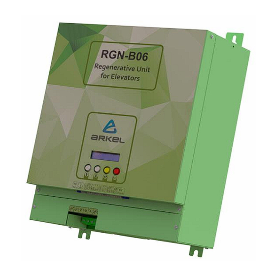
Summary of Contents for Arkel RGN-B06
- Page 1 RGN-B06 User Manual V1.12 RGN-B06 REGENERATIVE UNIT USER MANUAL...
- Page 2 Arkel is not responsible for those mistakes that may be found in this manual and for the damages that they may cause.
-
Page 3: Table Of Contents
RGN-B06 User Manual V1.12 TABLE OF CONTENTS INTRODUCTION ................................4 TECHNICAL SPECIFICATIONS ........................... 4 RGN-B06 OVERVIEW ..............................4 RGN-B06 CONNECTION TERMINALS ........................5 SAFETY INSTRUCTIONS ............................... 5 POWER LINES CONNECTIONS ............................ 6 6.1. DC Input Connections ................................. 6 6.2. Mains Output ..................................6 6.3. -
Page 4: Introduction
This energy causes internal bus voltage to rise. Traditionally, over a safety level of bus voltage, break resistors are used to waste this energy as heat. RGN-B06 feeds this potentially lost energy back to the... -
Page 5: Rgn-B06 Connection Terminals
RGN-B06 User Manual V1.12 Figure 1 Basic Connection (Fuses and safety devices not shown!) RGN-B06 CONNECTION TERMINALS Power Lines : Protective Earth Connection R, S, T : Grid Phases DC+, DC- : DC Input Connections Control Inputs IN1 ENABLE : Enable Signal... -
Page 6: Power Lines Connections
DC Input Connections This is the DC input terminal for RGN-B06 unit. DC BUS poles of the lift’s inverter system should be connected in right order for proper operation. RGN-B06 has an internal diode in order to protect itself against wrong connection. -
Page 7: Suggested Circuit Diagram
RGN-B06 User Manual V1.12 6.3. Suggested Circuit Diagram Figure 3 Suggested Connection Diagram * RCD, recommended against fire risks and insulation faults. (Ex: 300 mA) CONTROL SIGNAL CONNECTIONS Figure 4 User Interface and Control Signal Connections 7.1. Functions of the control inputs and relay outputs... -
Page 8: Control Inputs Connections
USER INTERFACE AND KEYPAD RGN-B06 includes a 2 X 16 character LCD and four navigation buttons. Output power or Error number is shown on the screen. Navigation buttons allows user to change the parameters and observe the current state of the device or some statistical information. -
Page 9: Keypad Functions
RGN-B06 User Manual V1.12 Keypad Functions SYMBOL USAGE Navigate between menus Increase the value of the selected parameter Navigate between menus Decrease the value of the selected parameter Enter the parameters menu Edit the value of a parameter See the sub items of a menu item... -
Page 10: Info Screens
Device starts running as soon as input voltage rises from the regulated grid base +40 V [+30 V, +110 V] START CURRENT The current as soon as RGN-B06 starts feeding the grid. 0.5 A [0.5 A , 5.0 A] FULL PW VOLT. -
Page 11: Installation And Comissioning
RGN-B06 User Manual V1.12 INSTALLATION AND COMISSIONING Each RGN-B06 unit is tested at factory and shipped ready to install. Still it is suggested to follow the steps below for safe installation and commissioning. • Connect PE and Grid R-S-T cables. -
Page 12: Error Messages
INPUT HIGH/LOW Input voltage is out of limits.. Check DC input connections and level. At least one of the ventilating fans does not Fans need to be changed, Apply ARKEL. FAN PROBLEM work properly MEASURE. PROBLEM Cannot measure temperature correctly.


Need help?
Do you have a question about the RGN-B06 and is the answer not in the manual?
Questions and answers