Arkel ARL-500 Programming Manual
Lift control system
Hide thumbs
Also See for ARL-500:
- Installation & operation manual (211 pages) ,
- Installation and user manual (49 pages)
Table of Contents
Advertisement
Quick Links
Advertisement
Table of Contents

Related Manuals for Arkel ARL-500


Summary of Contents for Arkel ARL-500
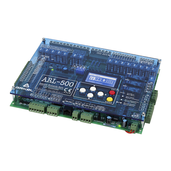
- Page 1 ARL-500 LIFT CONTROL SYSTEM Programming Manual...
- Page 2 Keep the manual in a safe place and available to engineering and installation personnel during the control panel functioning period. ARKEL is not responsible for those mistakes that may be found in this manual and for the damages that they may cause.
-
Page 3: Table Of Contents
5.3.3. REVKON PROGRAMMABLE INPUTS SCREENS ............... 18 5.3.4. KABKON PROGRAMMABLE INPUTS SCREENS ............... 19 5.4. OUTPUT STATUS SCREENS ........................... 20 5.4.1. ARL-500 FIXED RELAY OUTPUTS SCREEN ................20 5.4.2. ARL-500 PROGRAMMABLE RELAYS SCREENS ................. 20 5.4.3. ARL-500 PROGRAMMABLE TRANSISTORS SCREENS ............21 5.4.4. - Page 4 7.1.4. JUMPERs on ARL-500 main controller ....................92 7.1.4.1. Assigning the supply voltage of encoder in incremental positioning ............92 7.1.4.2. Activating the battery source of real time clock ....................92 7.1.5. LCD CONTRAST trimpot on ARL-500 controller ................92 7.2. REVKON C ........................93 ONTROLLER 7.2.1.
- Page 5 7.4.5. KKBT Non-indicator Call Module ....................... 121 7.4.5.1. KKBT Technical Data ............................122 7.4.5.2. KKBT Pin Assignments ............................ 123 7.4.5.3 Floor Setting With Dipswitches On KKBT ..................124 8. ARL-500 DISPLAY MESSAGES ....................125 8.1. STATUS MESSAGES ............................125 8.2. ERROR MESSAGES ............................132 ARL-500...
-
Page 6: General
The ARL-500 Lift Controller complies with: Lift Directive 95/16/EC - European standards EN 81-1, EN 81-2 1.2. ELECTROMAGNETIC COMPATIBILITY (EMC) The ARL-500 Lift Controller and its components comply with the standards according to Directives of electro magnetic compatibility 2004/108/EC - EN 55011 Issue 2007... -
Page 7: Manual Description
1.3. MANUAL DESCRIPTION Please read this manual carefully before installing the ARL-500 Lift Controller System. This manual will help you during installation of the ARL-500 controller and its components. In case of any problems, users are advised to contact manufacturer without any delay giving details of the problem. -
Page 8: Introduction
ARL-500 is universal. With just a few parameter changes; it can be used for rope traction or hydraulic elevators, with two-speed or VVVF, up to 48 stops, and for groups of up to 8 elevators. -
Page 9: Programming Interface
3. PROGRAMMING INTERFACE The user interface of ARL-500 lift controller system consists of 128x64 pixel resolution graphic LCD, keypads, LEDs, jumpers and trimpots. GRAPHIC LCD ARL-500 Controller has 128x64 pixel resolution illuminated blue graphic LC-Display. KEYPAD The ARL-500 controller is operated by using 6-key keypad. These keys have different functions in different displays. -
Page 10: Keypad Functions According To Screen
4. KEYPAD FUNCTIONS ACCORDING TO SCREEN The ARL-500 controller is operated by using 6-key keypad. The functions of keys according to screen are described in the tables below: Key functions in the main screen To previous/next monitoring screens Open service options screen... - Page 11 Increase / decrease value Select menu item / set Exit submenu / menu item Key functions in the change password submenu Move cursor left / right Increase / decrease value Select menu item / change Exit submenu / menu item ARL-500 ARKEL 2010...
- Page 12 Exit submenu / menu item Key functions in the parking settings submenu Move cursor left / right To next / previous menu item Increase / decrease value Select menu item / set Exit submenu / menu item ARL-500 ARKEL 2010...
-
Page 13: Display Screen
5. ARL-500 DISPLAY SCREEN The user interface of the ARL-500 controller is descripted below. The display of the ARL-500 controller is explained as required for installation and operating. ARL-500 Controller’s display screen consists of: Startup Screen Service Options Screen... -
Page 14: Main Screen
5.2. MAIN SCREEN ARL-500 controller’s main screen summarizes the lift operation and the status of the lift system within separated windows. Messages, aliases, symbols and signs used in main menu are descripted below. Limit switches 818: Up limit switch... - Page 15 Door open signal Door Status It displays the status of the car door. Door is opening and door is open. Door is closing. Door is closed. Door is locked. Door is disabled in the “Debug tools” screen. ARL-500 ARKEL 2010...
- Page 16 Special JF counter: ML1 and 142 signals signals ML1-ML2 counter: ML1 and ML2 signals Encoder counter: It displays current position of the car relative to leveled position of lowest landing in cm. Sample value “2588cm” ● “ML1 ML2 •” ARL-500 ARKEL 2010...
-
Page 17: Input Status Screens
5.3. INPUT STATUS SCREENS 5.3.1. ARL-500 FIXED INPUTS SCREEN In this screen some fixed inputs are monitored. The inputs which have ‘●’ (Closed) on the right hand side are active at the moment which have ‘.’ (Open) on the right hand side are inactive. -
Page 18: Programmable Inputs Screens
(4 Screens, PI1to PI14 programmable inputs) In this screen all of the programmable inputs of ARL-500 controller are monitored. The inputs which have ‘●’ (Closed) on the left hand side are active at the moment which have ‘.’ (Open) on the left hand side are inactive. -
Page 19: Kabkon Programmable Inputs Screens
2nd KABKON’s number is 2. All programmable inputs can be programmed by the user according to the needs of the system. Any input can be selected from the available inputs in the list of “KABKON inputs” menu. ARL-500 ARKEL 2010... -
Page 20: Output Status Screens
‘.’ (Open) on the right hand side are not active. 7 relays of ARL-500 controler are constant in the system. You cannot redefine or change the following relay output terminals: RU1, RU2, 11, RH1, RH2, RP, RSD, RF of ARL-500 controller. -
Page 21: Programmable Transistors Screens
5.4.3. ARL-500 PROGRAMMABLE TRANSISTORS SCREENS (2 Screens, PT1-PT6) In this screen all of the programmable transistors of ARL-500 controller are monitored.. The outputs which have ‘●’ (Closed) on the left hand side are active at the moment which have ‘.’ (Open) on the left hand side are inactive. -
Page 22: Canbus Status Screens
(KK-x), car operating panels (KABKON), inspection box (REVKON) and the main controller (ARL-500) are monitored. ARL-500 Lift Control System communicates with car and landing units through serial data communication using two separated CANbus line. CAN1 for landing units and CAN2 for car units. -
Page 23: The Status Of Landing Communication
‘A’ means connection of landing panel side A is made ‘B‘means connection of landing panel side B is made ‘-‘means no connection ‘AB‘means there is one LOP and serves to each entrance or there are 2 LOPS and 2 entrances. ARL-500 ARKEL 2010... -
Page 24: Group Status Screen
Below the meaning of numbers and signs used in the screen is described. Member ID The own ID of ARL-500 Controller in elevator group. It ID shows of Controller inside the parenthesis (A), (B), (C), (D), (E), (F), (G) or (H) The accepted calls of the elavator. -
Page 25: Error Status Screen
Controller can be blocked by the error after the maximum number of retries that is allowed. It is the only way to run lift again after it is blocked is controller reset. ARL-500 ARKEL 2010... -
Page 26: V-T (Velocity-Time) Travel Curve Screen
The travel settings adjusted by the parameters of ARL-500 and the frequency inverter are monitored with a V-T (Velocity-Time) travel curve graph. By the help of the travel curve screen you can observe the travelling of elevator system. -
Page 27: Car Command Entry Screen
Setting can be made by arrow keys within a range limited by a number of stops. Pressing ENTER will give a call order to the chosen landing or reset the given call. : selection of call entries : giving/cancelling a call : Returning to status screen ARL-500 ARKEL 2010... -
Page 28: Manual Drive Screen
UP/DOWN buttons on the keypad. UP button gives up direction command and DOWN button gives down direction command. When the inspection mode is activated at car or re- call operation is activated at control cabinet this mode will be ineffective. ARL-500 ARKEL 2010... -
Page 29: Service Options Screens
5.12. SERVICE OPTIONS SCREENS In this screen the service options of ARL-500 lift control system is monitored. The functions of service options are described below. Disable doors This function is used during installation, maintenance or servicing. When this function is activated, car calls are allowed but landing calls are not allowed. - Page 30 • If you hold down any of the buttons, you can see that button will start to blink faster. Thus, you can check if the call button is working properly or not. Random-10 ARL-500 will give 10 commands consecutively. Random-100 ARL-500 will give 100 commands consecutively. Random-500 ARL-500 will give 500 commands consecutively.
-
Page 31: Menu Settings
All settings for lift controller are stored in main menu parameters. Menu parameters are classified into several groups to make it easy for users. 6.1. ENTERING MENU The ARL-500 is password protected to prevent unauthorised manipulation of control parameters and endangerment of persons or impairment of the lift system resulting from unauthorised access. -
Page 32: Menu Tree
6.2. MENU TREE The ARL-500 main menu is displayed as a menu tree divided into submenus and menu items. System Settings Door Settings Call Responding Settings Display Settings Error Logs Programmable Inputs Programmable Outputs Hydraulic lift settings Shaft Learning... - Page 33 First time door close delay Wait on the floor Call responding settings Collection style Accept calls only in a single direction Avoid fake car calls checking lightbarrier Maximum car calls allowed at one time Cancelling car commands ARL-500 ARKEL 2010...
- Page 34 Inspection text Door open text Gray&Binary offset Show travel arrows Show collection arrows Error logs View error logs Delete error logs Programmable inputs ARL-500 inputs Input (PI-1) Input (PI-2) Input (PI-3) Input (PI-4) Input (PI-5) Input (PI-6) Input (PI-7) Input (PI-8)
- Page 35 Input (PI31-B1) Input (PI32-B1) Input (PI33-B1) Input (PI31-A2) KABKON-A2 inputs Input (PI32-A2) Input (PI33-A2) KABKON-B2 inputs Input (PI31-B2) Input (PI32-B2) Input (PI33-B2) KK-x inputs Programmable outputs ARL-500 transistors Transistor(PT1) Transistor(PT2) Transistor(PT3) Transistor(PT4) Transistor(PT5) Transistor(PT6) ARL-500 relays Relay(PR1) Relay(PR2) Relay(PR3) Relay(PR4) Relay(PR5)
- Page 36 Controller ID Bottom missing floors Top missing floors Parking settings Parking delay Parking time and parking floor settings Time and date settings System date and time Next maintenance date Motor protection settings R-S-T checking Motor temparature checking ARL-500 ARKEL 2010...
- Page 37 Daily UPS check Speed limit on rescue Program PLC Module Timer settings Timer number ON delay OFF delay Time unit Inputs PLC Input-1 PLC Input-2 PLC Input-3 PLC Input-4 Language Counters Stops on floors Reset counters Change password ARL-500 ARKEL 2010...
- Page 38 Emergency settings Primary fire exit Secondary fire exit Panic exit floor Headroom protection system Headroom/Pit protection Cartop protection lightbarrier Return to factory settings ARL-500 ARKEL 2010...
-
Page 39: Menu Parameters
Car do not stop at limits until the bottom or top limit switches interrupts the elevator. Do not stop at limits! This function must only be used for testing the limit switches and must be used carefully! ARL-500 ARKEL 2010... - Page 40 ►Inspection only When ARL-500 controller is switched on, it checks the bottom limit switch (817) to correct its position counter. If the inspection or recall control is activated before this correction drive, the system can only be operated in “Inspection only”.
- Page 41 Assign a programmable input to “25: (DRUN) Driver is during With feedback run” as a feedback signal input. The high signal (+24V) means driver is running and when the low signal (0V) is activated then the main contactors will be dropped. ARL-500 ARKEL 2010...
-
Page 42: Door Settings
This section is designed for selection of active doors at each floor and the door time setting. 6.3.2.1. Door Type Settings ARL-500 system can control up to two semi-automatic or full-automatic doors which can be enabled or disabled for each floor independently. Door type settings and number of doors. -
Page 43: Set Door Timings
This parameter is controlled by checking Manual door close close (terminal 130). When this timer overflows then an error waiting time is generated and the system goes to out of service. 10 – 300 seconds ►20 seconds ARL-500 ARKEL 2010... - Page 44 0 – 20 seconds ►2 seconds Enable approaching with car and landing doors open. The safety monitoring is integrated into the ARL-500 main board and enables car movements in the door zone with open car and landing doors. Door pre-opening Re-levelling function for hydraulic systems does not depend on this parameter.
-
Page 45: Call Responding Settings
A reasonable number is the specified maximum number of passengers. one time 1 – 32 calls ►5 Allowing to cancel car command by pressing to the same buton for Cancelling car twice. commands Allowed This function is enabled Not allowed This function is disabled ARL-500 ARKEL 2010... -
Page 46: Display Settings
A two-digit floor text can be set in a list of characters for each floor. This name is used by ARL-500 display and by all car/landing position indicators. List of characters using in ARL-500 for floor name texts Digits 0,1,…,9 Small letters a,b,…,z... -
Page 47: Dot Matrix Settings
“Out of service Floor:#1” “Out of Service Error:#2” When the system is out of service and it is because of the error no: 2, the message in display will appear like: “Out of service Error:#1” ARL-500 ARKEL 2010... - Page 48 Inspection the Recall mode is activated from recall hand terminal or the Manual text drive is activated from ARL-500 keypad, this message is displayed at dot matrix indicators. This message can be changed by using the keypad and selecting the letters one by one.
-
Page 49: Error Logs
These messages can be called up on the user interface of the ARL-500 or via HS500 hand terminal. Total errors: The number of total errors had occurred and stored in the memory. -
Page 50: Programmable Inputs
6.3.6. Programmable Inputs ARL-500 controller is available with 14 programmable inputs whose functions can be selected by the user. Additionally, there are 6 programmable inputs on the REVKON board, 3 programmable inputs on each KABKON board and 1 programmable input on each KK-x board that can be assigned functions by the user. -
Page 51: Revkon Inputs
6.3.6.2. REVKON inputs • In this menu, 6 rows of inputs (P21-PI26) are listed. REVKON inputs are shown on ARL-500 menu display as described below. “0: <undefined>” means no function is assigned to the input. Function number (Function alias) Function description... -
Page 52: Kabkon Inputs
48. Door side setting can be ‘A’ or ‘B’. ‘B’ is used for the second entrance. KABKON programmable input code used in ARL-500 display is described below: Input Door side KABKON number... -
Page 53: Kk-X Inputs
KK-x programmable input code shown in the upper row is described below: KK module - Landing number / Door side KK - KK-x programmable input function shown in the bottom row is described below: Function (Function alias) Function description number Undefined ARL-500 ARKEL 2010... -
Page 54: List Of Input Functions
Active low (0V) Recall operation is activated when low (0V) signal is detected from the input terminal. In normal operating mode high (24V) signal must be applied to the terminal. Recall down Recall operation DOWN Active high (+24V) ARL-500 ARKEL 2010... - Page 55 - All calls from floors are cancelled. - System allows only the calls from inside the car and from ARL-500 controller. - If the car lands to any floor and if there is no any other call, the doors are opened and they stay open on that floor.
- Page 56 K19N-A Close limit (not)-A Same function with close limit switch Active high (+24V) (K19A) but this input is high activated. K16N-B Open limit (not)-B Same function with open limit switch Active high (+24V) (K16B) but this input is high activated. ARL-500 ARKEL 2010...
- Page 57 Door close sgn (inv)-B The inverted close limit switch signal of Active high (+24V) door side B for fireman service. If the limit switch signal turns on when the door comes to its limit, this function is used. ARL-500 ARKEL 2010...
- Page 58 When this signal is not used, the ARL-500 controller turns off the speed signals and the direction signals together. The high signal (+24V) means the driver is running and the low signal (0V) means the driver stops.
- Page 59 This function is used if the brake checkback signal is connected to ARL-500 mainboard and the brake checkbeck is control by ARL-500. If the control is made by the inverter this input is not used. Manual evac. mode This function is used with MRL systems...
- Page 60 External error This function is used to give an external trip to ARL-500 controller. ARL-500 controller gives an error when a high (+24V) signal is detected from the input terminal. This error makes the elevator goes to out of service. When the high signal turns off, controller returns to normal operation.
- Page 61 PLC Input 1 Active high PLI2 PLC In-2 PLC Input 2 Active high PLI3 PLC In-3 PLC Input 3 Active high PLI4 PLC In-4 PLC Input 4 Active high PLI5 PLC In-5 PLC Input 5 Active high ARL-500 ARKEL 2010...
- Page 62 PLC Input 12 Active high PLI13 PLC In-13 PLC Input 13 Active high PLI14 PLC In-14 PLC Input 14 Active high PLI15 PLC In-15 PLC Input 15 Active high PLI16 PLC In-16 PLC Input 16 Active high ARL-500 ARKEL 2010...
-
Page 63: Programmable Outputs
“0: <undefined>” means no function is assigned to the output. Function number (Function alias) Function description Door-A close output (K3-A) The factory defaults of ARL-500 programmable transistors are listed in the table below: Output Function (Function Factory Function description... -
Page 64: Relays
6.3.7.2. ARL-500 Relays • In this menu, 8 rows of outputs (PR1-PR8) are listed. Programmable outputs are shown on ARL-500 menu display as described below. “0: <undefined>” means no function is assigned to the output. Function number (Function alias) Function description... -
Page 65: Revkon Relays
6.3.7.3. REVKON Relays • In this menu, 3 rows of outputs (PR21-PR23) are listed. REVKON relay outputs are shown on ARL-500 menu display as described below. “0: <undefined>” means no function is assigned to the output. Function number (Function alias) -
Page 66: List Of Output Functions
ON when encoder is counting upwards Encoder down ON when encoder is counting downwards ED12 Encoder moving ON when encoder is counting up or down Binary code Floor number binary code bit- Binary code Floor number binary code bit- ARL-500 ARKEL 2010... - Page 67 Mains active Mains active output. ON when mains power is active. Mains power is controller by the inputs on ARL-500 controller (L1, L2, L3, N). UPT Test Supply of UPS phase input is For MRL connected over a UPS test systems.
- Page 68 The same function must be assigned to the programmable output. So that any programmable input of the elevator system can be bridged to any programmable output virtually by the ARL-500 controller. Bridge-2 A virtual output-2 Bridge-3 A virtual output-3 Bridge-4 A virtual output-4...
- Page 69 The car is on floor 5 Active high Level mod 8-6 The car is on floor 6 Active high Level mod 8-7 The car is on floor 7 Active high Level mod 8-8 The car is on floor 8 Active high ARL-500 ARKEL 2010...
-
Page 70: Encoder Settings
Set this parameter “Slowing distance in low speed” same as the ADrive low speed parameter “1.9 Stopping distance”. For example if ADrive parameter “1.9 Deceleration distance” is set to 20cm, set this parameter to 20cm. 0 – 200 mm ►60 mm ARL-500 ARKEL 2010... -
Page 71: Hardware Configuration
If this value is changed after a shaft-learning drive, a new shaft-learning run must be required. Because during the shaft-learning run, ARL-500 will determine the relation between pulse- count and centimeters by using this “flag length” information. -
Page 72: Hydraulic Lift Settings
Time passed after the pawl is released until the pawl is locked. maximum delay 0,1 – 5 seconds ►5 seconds PAWL device delay Time passed after the car lands to a floor until the pawl device is released. before release 0,1 – 5 saniye ►1 seconds ARL-500 ARKEL 2010... -
Page 73: Group Settings
6.3.10. Group Settings After connection of control panels in the elevator group only to do is setting each controller as A,B,C,…,H on ARL-500 menu. Each controller must have a different group The controller ID used by each controller in group operation. Controller Controller ID ID must be adjusted differently within each controller. -
Page 74: Parking Settings
Because there is no active call and parking delay is exceeded the controller sends the car to a programmed parking floor. The ARL-500 controller has a scheduler that enables time dependent park drive programs. Each day can de divided in 5 time zones. -
Page 75: Time And Date Settings
This section is used to adjust time and date setting and the make the maintenance configuration. 6.3.12.1. System date and time The date and the time of the ARL-500 controller. These settings must be checked during each service and adjusted if necessary. If the time is not set correctly, the time information of the error storage are useless. -
Page 76: Motor Protection Settings
6.3.13. Motor Protection Settings This section is used to make the phase and motor protection settings. ARL-500 controller is available with integrated phase and motor protection circuits. Enables the phase loss and phase sequence checking. R-S-T checking ►Enabled When this parameter is set to “enable”, the terminals L1, L2, L3, Disabled and N on ARL-500 controller must be connected properly. -
Page 77: Sound Settings
Hall button Enables the sound for landing call button when pressed. sounds ►On Car button Enables the sound for landing call buttons when pressed sounds ►On Enables the sound for car call buttons when pressed. Emergency alarm ►Off ARL-500 ARKEL 2010... -
Page 78: Rescue Settings
In this submenu, the settings for evacuation operation (when mains power off) are adjusted. The evacuation type of elevator. Rescue method No rescue No rescue device. External (AKUS) ARKEL AKUS-SD evacuation unit is used (for only asynchrous drives). By releasing brake Evacuation operation with brake releasing method (for only synchrous drives). Zetadyn Evacuation operation by ZetaDYN inverter with UPS supply. - Page 79 The maximum evacuation time for the evacuation opeation if controlled by ARL-500 controller. Maximum time to When no floor level signal is detected in this period during rescue evacuation, controller interrupts the evacuation. This parameter must be set to a maximum time of floor to floor travel.
-
Page 80: Language
6.3.16. Language This section is used to set the of graphic LCD and ARL-500 menu language The language of graphic LCD and ARL-500 menus. These languages are served in two packs. 5 languages are only Language available with each pack. -
Page 81: Change Password
6.3.18. Change Password This section is used to set the password asked when entering the ARL-500 menu. User password has six digits. The default setting for the password is “000000” and you probably used this password to enter the menu. It is highly recommended to change it to an individual one before setting the lift parameters. -
Page 82: Emergency Settings
“panic exit” floor. - After landing to designated floor, system opens the doors and cancels emitting the alarm. Lastly, system deactivates the “panic input” signal and starts to operate in normal mode. 1 – 48 ►1. Floor ARL-500 ARKEL 2010... -
Page 83: Headroom/Pit Protection
The switches are connected to ARL-500 to detect if a switch is opened. The switch breaks when the corresponding landing door is opened. If a limit switch is broken and the car in not at that floor ARL-500 makes elevator operate only in inspection mode. -
Page 84: Return To Factory Settings
6.3.21. Return to Factory Settings If you want to set all parameters to the values set just after production then you can use this section. It clears all the parameters entered by the user and set them to factory defaults. ARL-500 ARKEL 2010... -
Page 85: Technical Data
7. TECHNICAL DATA 7.1. ARL-500 MAIN CONTROLLER 1 Drive relays (not programmable) 2 Programmable relays (can be programmed from ARL-500 menu) 3 Programmable outputs (can be programmed from ARL-500 menu) 4 Programmable inputs (can ben programmed from ARL-500 menu) 5 Door bridging safety circuit... -
Page 86: Technical Data
7.1.1. ARL-500 Technical Data Description Value Dimensions 260 × 200 × 35 Length × width × height (mm) Working temperature ±0 - +60 °C Degree of protection IP20 Supply voltage 24 VDC ± 5 VDC Power consumption 400mA Control inputs... -
Page 87: Terminals & Pin Assignment
7.1.2. ARL-500 TERMINALS & PIN ASSIGNMENT ARL-500 ►X1 : Drive Operation Terminals (Not programmable) Two Speed VVVF Hydraulic Down Direction Contactor Down Direction Contactor VC : Slow-Down Valve Up Direction Contactor Up Direction Contactor VA : Slow-Up Valve Contactors Supply Common... - Page 88 ARL-500 ►X5 : Motor Protection & Phase Failure Terminals Panel Thermostat & Motor Thermistor & T1- T2 Brake Resistor Thermostat (VVVF) & Oil Thermostat (Hydraulic) Neutral L1,L2,L3 Main Phase ARL-500 ►X6 : Signal Circuit Supply Terminals Signal Circuit Supply Input (+24VDC)
-
Page 89: Leds On Arl-500 Main Controller
5V power supply of the processor is not working correctly. The hardware of the ARL-500 ontroller is faulty. Power on. Green Power off. 24V power supply of ARL-500 controller is not working correctly. Power on. Power off. Green 5V power supply of I/O peri-pherals is not working correctly. - Page 90 LEDs of programmable relays Color State Description Programmable relay 1 activated Programmable relay 2 activated Programmable relay 3 activated Programmable relay 4 activated Programmable relay 5 activated Programmable relay 6 activated Programmable relay 7 activated Programmable relay 8 activated ARL-500 ARKEL 2010...
- Page 91 Door bridging enable relay RBE activated Door zone magnetic switch SML1 closed Green Door zone magnetic switch SML2 closed Green LEDs of encoder inputs Color State Description Green Encoder signal phase A activated Green Encoder signal phase B activated ARL-500 ARKEL 2010...
-
Page 92: Jumpers On Arl-500 Main Controller
7.1.4.1. Assigning the supply voltage of encoder in incremental positioning With incremental positioning, encoder supply voltages are assigned by using the encoder jumpers on ARL-500 controller. Two jumpers are used for each setting. 12V jumpers are delivered plugged at its rest position. It must be set according to the encoder supply voltage before operating ARL-500 controller. -
Page 93: Revkon Car Top Controller
7.2. REVKON Car Top Controller 1 Programmable relays (can be programmed from ARL-500 menu) 2 Programmable inputs(can be programmed from ARL-500 menu) 3 Emergency light relay 4 Car fan relay 5 Car light relay 6 Programming socket 7 Battery fuse... -
Page 94: Revkon Technical Data
REVKON A = 212mm G = 68mm B = 254mm H = 50mm C = 162mm I = 37mm D = 172mm J = 34mm E = 111mm K = 5mm F = 118mm L = 4mm ARL-500 ARKEL 2010... -
Page 95: Revkon Terminals & Pin Assignment
REVKON ►XKON : KABKON Connector (10-pin) REVKON ►X-CB1 : Inspection Box CANbus Socket (4-pin) REVKON ►X-CB2 : Inspection Box CANbus Socket (4-pin) REVKON ►X21 : Alarm Horn Terminals HOP+ Alarm Horn + Terminal HOP- Alarm Horn – Terminal ARL-500 ARKEL 2010... - Page 96 Auxiliary Low Voltage Terminals YL2 (YK1) Intercom Button Inspection Alarm Button YL3 (AL) REVKON ►X27 : Car High Voltage Terminals Earth Car Supply Car Neutral YH5(3) Car shaft lighting phase Car shaft lighting contact YH4(3S) Auxiliary High Voltage Terminals ARL-500 ARKEL 2010...
- Page 97 The common supply voltage for signals ML1, ML2, 141 and 142. If 100 (+24Vdc) is present MLO puts out 24Vdc. If not MLO puts out 12Vdc from the battery voltage in inspection box. Supply Voltage (+24Vdc) 1000 Supply Voltage (0Vdc) ARL-500 ARKEL 2010...
-
Page 98: Leds On Revkon Car Top Controller
Description PI21 Yellow Programmable Input 21 activated PI22 Yellow Programmable Input 22 activated PI23 Yellow Programmable Input 23 activated PI24 Yellow Programmable Input 24 activated PI25 Yellow Programmable Input 25 activated PI26 Yellow Programmable Input 26 activated ARL-500 ARKEL 2010... - Page 99 Description PR21 Programmable relay 1 activated PR22 Programmable relay 2 activated PR23 Programmable relay 3 activated LEDs of car relays Color State Description Car emergency light switched on RFAN Car fan switched on Car light switched on ARL-500 ARKEL 2010...
-
Page 100: Kabkon Car Panel Module
16 X-CB1: Small size CANbus socket for car position indicator (LCD or Dot-matris display) connection 17 X-CB2: 2 pcs. big size CANbus socket for 2nd KABKON connection or HS500 hand terminal connection 18 XKON: REVKON connection socket ARL-500 ARKEL 2010... -
Page 101: Kabkon Technical Data
Max. 500 mA load @ 12Vdc Emergency lighting output Approximately 2 hours duration with 1.3 Ah battery. Gong output 0,5W/8Ohm speaker KABKON Dimensional Drawing A = 88mm B = 96mm C = 139mm D = 147mm E = 4mm ARL-500 ARKEL 2010... -
Page 102: Kabkon Terminals & Pin Assignment
Door Close Button & Indicator Supply Voltage (+24VDC) L-KAPA Indicator Output (0VDC) S-KAPA Button Input (High active) KABKON ► VAT : Car Priority Switch Socket (3-pin) Car Priority Switch & Indicator Supply Voltage (+24VDC) L-VAT Indicator Output (0VDC) S-VAT Button Input (High active) ARL-500 ARKEL 2010... - Page 103 Light Supply Ground 1000 Light Supply Ground KABKON ► HOP : Gong Output Socket (3-pin) Supply Voltage (+24VDC) Gong Output Supply Voltage (+24VDC) * : The top pin when the “KABKON” text written on board is read straight. ARL-500 ARKEL 2010...
-
Page 104: Leds On Kabkon Car Command Cotrol Module
7.3.4. Trimpot on KABKON module Trimpot on KABKON module is used for adjusting volume of gongs in car operating panel. Gong volume is finely increased by turning trimpot anti-clockwise and is decreased by turning trimpot clockwise. ARL-500 ARKEL 2010... -
Page 105: Dip-Switches On Kabkon Module
Number of commands selection The settings for number of car commands are described below: Set for car commands between 1 and 24 (KABKON board with this setting is showed as “KABKON1” on ARL-500 display) Set for car commands between 25 and 48 (KABKON board with this setting is showed as “KABKON2”... -
Page 106: Call/Indicator Modules
1 CANbus connection sockets (big size) 2 CANbus connection socket (small size) 3 PC connection socket for programming 4 LCD contrast adjustment setting 5 4-key keypad 6 Buzzer for button sounds 7 PC programming socket 8 Memory chip ARL-500 ARKEL 2010... -
Page 107: Lcd240X128A Technical Data
B = 136.2mm J = 15mm C = 102mm K = 23mm D = 117.6mm L = 68.1mm E = 125mm M = 144mm F = 110mm N = 159.1mm G = 51mm P = 4mm H = 64mm ARL-500 ARKEL 2010... -
Page 108: Kklcd-A/Kklcd-B/Kklcd-C Call/Indicator Modules
1 Down direction led connection socket 2 Up direction led connection socket 3 Gong connection socket 4 Programmable input output connection socket 5 CANbus connection socket 6 2-key keypad 7 Gong volume setting. 8 PC programming socket 9 MCU programming socket ARL-500 ARKEL 2010... -
Page 109: Kklcd-A/Kklcd-B/Kklcd-C Technical Data
B = 113mm C = 93mm D = 56.5mm E = 40mm F = 72mm G = 20.7mm H = 21.5mm J = 4mm KKLCD-A K = 13mm L = 19mm P = 7mm R = 3mm ARL-500 ARKEL 2010... - Page 110 A = 78mm B = 70mm C = 42mm D = 44mm E = 62mm F = 19.5mm G = 18mm H = 19mm J = 13mm KKLCD-C K = 7mm L = 3mm M = 4mm ARL-500 ARKEL 2010...
-
Page 111: Kklcd-A/Kklcd-B/Kklcd-C Pin Assignments
X-CB1 Car CANbus Socket (4-pins) 100 * +24VDC Supply 1000 GND (Ground) CANL First CANbus terminal CANH Second CANbus terminal * : The leftmost pin behind KKLCD-X (socket writing must be on the top side of the card). ARL-500 ARKEL 2010... - Page 112 Doors A and B PARAMETER 3: BUTTON EXISTANCE SETTING When “Buton” is written in the indicator, with “+” button you can Buton choose if there is button connected to module or not. There is button There is no button ARL-500 ARKEL 2010...
-
Page 113: Kk3X3057 Dot-Matrix Call/Indicator Modules
2 Up direction button connection socket 3 Speaker connection socket 4 Programmable input-output connection socket 5 CANbus connection socket (small size) 6 CANbus connection socket (big size) 7 2-key keypad 8 Gong volume setting 9 MCU programming socket ARL-500 ARKEL 2010... -
Page 114: Kk3X3057 Technical Data
C = 109mm D = 114mm E = 45.7mm F = 38mm H = 22.8mm J = 17mm K = 15mm L = 18.5mm M = 7mm P = 7mm R = 4mm S = 3mm KK3X3057 ARL-500 ARKEL 2010... -
Page 115: Kk3X3057 Pin Assignments
X-CB1 Car CANbus Socket (4-pins) 100 * +24VDC Supply 1000 GND (Ground) CANL First CANbus terminal CANH Second CANbus terminal * : The leftmost pin behind KK3X3057 (socket writing must be on the top side of the card). ARL-500 ARKEL 2010... -
Page 116: Kk3X3057 Floor Adjustment
Door A and B PARAMETER 3: BUTTON EXISTANCE SETTING When “B” is written in the indicator, with “+” button you can choose if there is button connected to module or not. There is button There is no button ARL-500 ARKEL 2010... -
Page 117: Kk2X3057 Dot-Matrix Call/Indicator Modules
7.4.4 KK2X3057 Dot-matrix Call/Indicator modules 1 Down direction button connection socket 2 Up direction button connection socket 3 Speaker connection socket 4 Programmable input-output connection socket 5 CANbus connection socket 6 2-key keypad 7 Gong volume setting 8 MCU programming socket ARL-500 ARKEL 2010... -
Page 118: Kk2X3057 Technical Data
KK2X3057 Dimensional Drawing A = 49mm B = 73mm C = 58mm D = 64mm E = 45.7mm F = 38mm G = 14mm H = 13mm J = 12mm K = 4mm KK2X3057 L = 3mm ARL-500 ARKEL 2010... -
Page 119: Kk2X3057 Pin Assignments
X-CB1 Car CANbus Socket (4-pins) 100 * +24VDC Supply 1000 GND (Ground) CANL First CANbus terminal CANH Second CANbus terminal * : The leftmost pin behind KK2X3057 (socket writing must be on the top side of the card). ARL-500 ARKEL 2010... -
Page 120: Kk2X3057 Floor Adjustment
Door A and B PARAMETER 3: BUTTON EXISTANCE SETTING When “B” is written in the indicator, with “+” button you can choose if there is button connected to module or not. There is button There is no button ARL-500 ARKEL 2010... -
Page 121: Kkbt Non-Indicator Call Module
1 Down direction button connection socket 2 Up direction button connection socket 3 Speaker connection socket 4 Programmable input-output connection socket 5 CANbus connection socket 6 Dipswitches for floor number setting 7 Gong volume setting 8 MCU programming socket ARL-500 ARKEL 2010... -
Page 122: Kkbt Technical Data
15mA, 0.4W @ 24VDC Button-led (for each button) Gong 0.5W/8Ohm speaker Programmable output Max. 100mA, 2.5W @ 24VDC KKBT Dimensional Drawing A = 33mm B = 41mm C = 26mm D = 52mm E = 4mm F = 3mm KKBT ARL-500 ARKEL 2010... -
Page 123: Kkbt Pin Assignments
X-CB1 Car CANbus Socket (4-pins) 100 * +24VDC Supply 1000 GND (Ground) CANL First CANbus terminal CANH Second CANbus terminal * : The rightmost pin behind KK2X3057 (socket writing must be on the top side of the card). ARL-500 ARKEL 2010... -
Page 124: Floor Setting With Dipswitches On Kkbt
0 + 16 + 8 + 0 + 2 + 1 + 1 = 28 This landing call panel is indicated as “KK-28” on ARL-500 display. For door selection switches, use the table below: This panel commands both door-A and door-B... -
Page 125: Display Messages
8. ARL-500 DISPLAY MESSAGES 8.1. STATUS MESSAGES The current status of elevator during the operations of controller is shown on ARL-500 display with the information on the top of display we called status message. The status messages are listed in the following table. - Page 126 (817) to sensors... correct its position counter. Earthquake evacuation mode is activated. The earthquake sensor input Earthquake (terminal DEP) on the ARL-500 evac. controller is active. Fire evacuation mode is activated. The fireman input (terminal YAN) Fire evacuation on the ARL-500 controller is active.
- Page 127 119. The stop circuit contacts between terminal 110 and 120 interrupted the safety circuit. All safety circuit inputs of ARL-500 controller are idle. - Emergency stop switch may be operated on the remote control Stop circuit off unit in normal mode (not Inspection or Recall).
- Page 128 “System settings > Limiters in inspection mode” either "Stop car immediately” or “Stop car at floor level” in the ARL-500 menu. The top limit switch (SKSR2) is activated Car is at the top floor and the top Inspection: 818 in inspection mode.
- Page 129 The manual control by keypad is active. LEFT + RIGHT keys on the ARL-500 keypad are pressed Inspection(*) together are lift goes into manual control mode from keypad. The bottom limit switch (SKSR1) is...
- Page 130 Cabin is ready for any command Ready (inside door-zone) command entry and inside entry. door zone. The system is ready for any command entry and outside Cabin is ready for any command Ready (outside door-zone) door zone. entry. Status Message Description Reason ARL-500 ARKEL 2010...
- Page 131 To operate in normal mode, at Safety circuit must be very first the system must learn shaft, safety circuits must be complete during shaft the shaft and to learn the shaft complete. learning! the safet circuit must be complete. ARL-500 ARKEL 2010...
-
Page 132: Error Messages
8.2. ERROR MESSAGES The current error of the elevator system is shown in error status screen on ARL-500 display we called error message. ARL-500 controller saves these error messages listed in the following table. Error Message Description Reason - Check motor drive Max. -
Page 133: Arkel
T1-T2 - Motor overheated. Monitoring Temperature monitoring of the drive via input of motor thermistor Motor on T1-T2 terminals of ARL-500 has terminals T1-T2. temperature too triggered. The voltage of terminal T1 is - The thermostat in the control high or PTC not 24VDC. - Page 134 Fire detected - Check the connection of terminal with 24V when a fire detected in YAN on ARL-500 system. The 24V supply of the ARL-500 board Power supply (100-1000) is below the permitted Check power supply and wiring voltage too low range of 24V - 20%.
- Page 135 ML1 and ML2 switches are activated simultaneously. simultaneously. Short-circuit? Check the “group settings” in the Group ID main menu and change the conflict. Change Group ID conflict in group operation. controller ID parameter if there are group ID. any conflicts. ARL-500 ARKEL 2010...
- Page 136 Inspection only! lightbarrier”. Check assigned PPSx input This error is triggered when A door connections on ARL-500. Pit protection assigned to one of the PPSx inputs was If this function is not used in your switch did not...
- Page 137 ARKEL Elektrik Elektronik Ticaret Ltd. Şti. Bostanci Yolu Cad. Şehit Sok. No:36 Yukari Dudullu Istanbul TURKIYE Tel: (+90 216) 540 03 10 - 11 -12 Fax: (+90 216) 540 03 09 E-mail : info@arkel.com.tr www.arkel.com.tr ARL-500 ARKEL 2010...
Need help?
Do you have a question about the ARL-500 and is the answer not in the manual?
Questions and answers
I need arl 500 password
The default password for the Arkel ARL-500 is “000000”.
This answer is automatically generated