Table of Contents
Advertisement
Quick Links
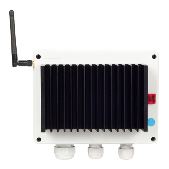
3kW, 6kW and 9kW
Remote Variable Heater
Controller (Receiver)
Safety Instructions and Operation Manual
901324
901316
901344
3kW Remote Variable Controller
6kW Remote Variable Controller
9kW Remote Variable Controller
Unit 9, Stort Valley Industrial Estate
Stansted Road, Bishop's Stortford
Hertfordshire, United Kingdom
CM23 2TU
Available at
www.shadowindustrial.co.uk
01279 466500
info@shadowindustrial.co.uk
Advertisement
Table of Contents

Related Manuals for Shadow 901324

Summary of Contents for Shadow 901324
- Page 1 3kW, 6kW and 9kW Remote Variable Heater Controller (Receiver) Safety Instructions and Operation Manual 901324 3kW Remote Variable Controller 901316 6kW Remote Variable Controller 901344 9kW Remote Variable Controller Unit 9, Stort Valley Industrial Estate Available at Stansted Road, Bishop’s Stortford www.shadowindustrial.co.uk...
-
Page 2: Table Of Contents
Contents Important Information . . . . . . . . . . . . . . . 3 Safety Instructions . . . . . . . . . . . . . . . . . 4 Cleaning &... -
Page 3: Important Information
Important Information Please carefully read all instructions provided before using this appliance . The controller must be installed and used as instructed . This Operation Manual contains the important safety information, as well as some recommendations on correct use, installation and maintenance of the appliance . When operating the controller observe necessary safety precautions, as improper use may result in injury or damage to property . -
Page 4: Safety Instructions
Safety Instructions Read these instructions before using. WARNING Potential fire risk if the controller is covered by any flammable materials. • Ensure that the controller’s vents and cooling fans are clean and free from obstructions to prevent overheating . • Do NOT use in unventilated areas . •... -
Page 5: Cleaning & Maintenance
Cleaning & Maintenance • Isolate the appliance from the power supply system . • After the appliance has cooled down, the housing can be wiped clean with a damp cloth . • Wipe the appliance only with a clean and lint-free cloth or a soft brush . •... -
Page 6: Assembly Instructions
Assembly Instructions Isolate the Mains before removing the cover . Remove the cover by removing the 4 screws . There is a terminal strip connector for connecting the Mains IN and Mains OUT . Use the three cable glands to bring the Mains cables into and out of the controller base . -
Page 7: Qhvcr Master Controller (Transmitter)
QHVCR Master Controller (Transmitter) There are three control dials Blue, Yellow & Red one for each zone. The QHCxxMR units are preset to operate in one of these zones. The QHCxxMR unit once preset will only operate in that designated zone. The factory setting is 1, which is the Blue control dial . - Page 8 Please note: The QHVCR remote Master Controller can control any number of QHCxxMR controllers as long as they are within range, up to 100 meters* (see specification sheet for the QHVCR unit) . The QHVCR should be wall mounted . *Longer antennae are available to extend the range up to 200 meters .
-
Page 9: Pairing Programming Devices Qhvcr & Qhcxxmr
Pairing Programming Devices QHVCR & QHCxxMR The Left Hand Side rotary switches (TEN) on both boards must be set the same . The RF frequency setting must match on both boards . There are 10 possible frequencies that can be selected from 0-9 . If the settings on the LHS switch (TEN) do not match the devices will fail to operate . -
Page 10: Pir Motion Detectors & Operation
PIR Motion Detectors Connection & Operation PIR motion detectors are passive infrared sensors and electronic devices that are triggered by infrared light from the movement of objects in their field of view. We recommend the QHPIR is used with our QHC controllers . Connecting the PIR to the QHCxxMR will enable the controller to turn ON only once the presence of a person is detected by the PIR . -
Page 11: 7-Day Programmable Fitting Option
7-Day Programmable Timer Fitting Option A 7-Day programmable timer can be fitted as an option instead of the PIR. It is important to note that only one or the other can be fitted to the QHCxxMR controller, not both. S1 & S2 are found on the printed circuit board (PCB) QHPCB-A, See Fig 12 . Default Settings for S1 &... -
Page 12: Expandable Heating System
Expandable Heating System Using a QHVCR & Multiple QHC03MR, QHC06MR & QHC09MR Controllers Using the remote 3-zone QHVCR controller the area being heated can be zoned into three area’s Blue, Yellow & Red. Each zone can be controlled separately, this includes setting each zone at a different level. -
Page 13: Troubleshooting
Troubeshooting The QHCxxMR (receiver) is not working: Check that the unit is wired correctly and follow the installation procedure on page 6. The neon indicator should be ON to indicate that the Mains are connected correctly . Then check that the status LED D5, the +5v LED D6 & the +12v LED D7 are all ON green. If the status LED is Red, this indicates that there is a problem with the mains connection to the board . -
Page 14: Technical Data
Technical Data Supply voltage: Single Phase 240V AC 50 Hz Max. Load capacity: 3 kilo Watts (QHC03MR), 6 kilo Watts (QHC06MR), and 9 kilo Watts (QHC09MR). Over Temperature Protection: On each O/P - LED indicators 1,2 & 3 Input: Live (Brown) terminal #2 Neutral (Blue) terminal #3... - Page 15 Unit 9, Stort Valley Industrial Estate Stansted Road, Bishop’s Stortford Hertfordshire, United Kingdom CM23 2TU Avaiable at www.shadowindustrial.co.uk 01279 466500 info@shadowindustrial.co.uk...
Need help?
Do you have a question about the 901324 and is the answer not in the manual?
Questions and answers