Table of Contents
Advertisement
Quick Links
QHC18MR 18kW and QHC24MR
24kW Heater Controller 3
Channel (Receiver) Remote &
Manual Operation
Safety Instructions and Operation Manual
901253
901255
QHC18MR 18kW
QHC24MR 24kW
Unit 9, Stort Valley Industrial Estate
Stansted Road, Bishop's Stortford
Hertfordshire, United Kingdom
CM23 2TU
Available at
www.shadowindustrial.co.uk
01279 466500
info@shadowindustrial.co.uk
Advertisement
Table of Contents

Related Manuals for Shadow QHC18MR 18kW QHC24MR 24kW

Summary of Contents for Shadow QHC18MR 18kW QHC24MR 24kW
- Page 1 QHC18MR 18kW and QHC24MR 24kW Heater Controller 3 Channel (Receiver) Remote & Manual Operation Safety Instructions and Operation Manual 901253 QHC18MR 18kW 901255 QHC24MR 24kW Unit 9, Stort Valley Industrial Estate Available at Stansted Road, Bishop’s Stortford www.shadowindustrial.co.uk Hertfordshire, United Kingdom 01279 466500 CM23 2TU info@shadowindustrial.co.uk...
-
Page 2: Table Of Contents
Contents Important Information . . . . . . . . . . . . . . . 3 Safety Instructions . . . . . . . . . . . . . . . . . 4 Cleaning &... -
Page 3: Important Information
Important Information Please carefully read all instructions provided before using this appliance . The controller must be installed and used as instructed . This Operation Manual contains the important safety information, as well as some recommendations on correct use, installation and maintenance of the appliance . When operating the controller, observe necessary safety precautions, as improper use may result in injury or damage to property . -
Page 4: Safety Instructions
Safety Instructions Read these instructions before using. WARNING Potential fire risk if the controller is covered by any flammable materials. • Ensure that the controller’s vents and cooling fans are clean and free from obstructions to prevent overheating . • Do NOT use in unventilated areas . •... -
Page 5: Cleaning & Maintenance
Cleaning & Maintenance • Isolate the appliance from the power supply system . • After the appliance has cooled down, the housing can be wiped clean with a damp cloth . • Wipe the appliance only with a clean and lint-free cloth or a soft brush . •... -
Page 6: Assembly Instructions
Assembly Instructions When unpacking the controller, please make sure that all the items are present, there are no components left in the box and that all the parts are not damaged . Begin by removing the service hatch and remove the 4 fixing screws, 2 at the top and 2 at the bottom . -
Page 7: Din Rail Connection
Remove the white, yellow & red wire links . If the wire links or external push button are not fitted, then the unit will not operate when S2 is in the ON position. Din Rail Connection Fig 1 Only a qualified electrician should install this device. Din Rail Connection... -
Page 8: Controller Setup Manual Operations1 & S2
Controller Setup Manual Operation S1 & S2 To access S2, remove both the service hatch & front panel. S2 is found on the printed circuit boards QHPCB-A . There is a set on each board, see Fig . 3 . To switch the PIR &... -
Page 9: Qhvcr Master Controller (Transmitter)
QHVCR Master Controller (Transmitter) Fig 4 The three control dials on the QHVCR are Blue, Yellow & Red, one for each zone. The QHCxxMR units are preset to operate in one of these zones. Once the QHCxxMR unit is preset, it will only operate in that designated zone. The factory setting is 1, which is the Blue control dial . - Page 10 To change a setting just press the ON/Standby button and proceed as described above in sections 2 & 3 . However, while the QHVCR unit is ON, you can turn OFF all the heaters by pressing the ON/Standby button, which is indicated by the LED indicator flashing Red.
-
Page 11: Pairing Programming Devices Qhvcr & Qhcxxmr
Pairing Programming Devices QHVCR & QHCxxMR Fig 5 The Left Hand Side rotary switches (TEN) on both boards must be set the same . The RF frequency setting must match on both boards . There are 10 possible frequencies that can be selected from 0-9 . If the settings on the LHS switch (TEN) do not match the devices will fail to operate . -
Page 12: Pir Motion Detectors & Operation
PIR Motion Detectors Connection & Operation PIR motion detectors are passive infrared sensors and electronic devices that are triggered by infrared light from the movement of objects in their field of view. We recommend the QHPIR is used with our QHC controllers . When using a PIR, the S2 slide switch must be in the ON position (select 1), see Fig 3 on page 8 . -
Page 13: External Switch Connection & Operation
External Switch Connection & Operation External switches can be connected to the controller via terminals #18,19 & 20 a+b . This particular terminal is a Double deck terminal . The switch must be a normally open contact switch (NO) and contacts must be voltage free . When using External Switches, the S2 slide switch must be in the ON position (select 1) . -
Page 14: Jumper Link (Pir) & Link Bar (External Switch)
Jumer Link (PIR) & Link Bar (External Switch) The Jumper Link should be fitted to inputs #15-17 (PIR) & the Link Bar should be fitted to inputs #18-20 (External switch) . Fig 10 Jumer Link (PIR) & Link Bar (External Switch) -
Page 15: Over Temperature Protection
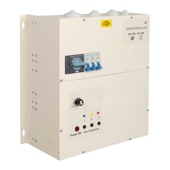
Over Temperature Protection There are 3 temperature sensors and 3 LED indicators, one for each zone. The LED indicators are located on the front panel marked 1, 2 & 3 . When an over-temperature situation is detected one of these will flash to indicate which zone has overheated. The controller will automatically reduce the power to the affected zone to 50%. -
Page 16: Fitting Connnectors Id Red & Yellow
Fitting ID Connectors Red & Yellow Fig 11 Master 1 Blue printed circuit board (PCB) is located in position 1, phase L1 . This is the main board that controls the entire QHC18MR and QHC24MR controller . The Slave 2 & 3 Red &... -
Page 17: Technical Data
Technical Data Supply voltage: Three Phase 415V AC 50/60 HzAll O/P’s with Soft start Max. Load capacity: 18 kilo Watts (QHC18MR) and 24 kilo Watts (QHC24MR). The load must be balanced across all 3 outputs max 6Kw (QHC18MR) and 8kW (QHC24MR) Over Temperature Protection: On each O/P - LED indicators 1,2 &... - Page 18 Unit 9, Stort Valley Industrial Estate Stansted Road, Bishop’s Stortford Hertfordshire, United Kingdom CM23 2TU Avaiable at www.shadowindustrial.co.uk 01279 466500 info@shadowindustrial.co.uk...
Need help?
Do you have a question about the QHC18MR 18kW QHC24MR 24kW and is the answer not in the manual?
Questions and answers