
Related Manuals for Varifan MST-1

Summary of Contents for Varifan MST-1
- Page 1 MST-1 USER’S MANUAL DIFF TIM ER reduc. per day ADJUST Varifan ® MST-1 www,monitrol.com...
- Page 2 MST-1 Although the manufacturer has made every effort to ensure the accuracy of the information contained herein, this document is subject to change without notice due to ongoing product development. WARNINGS AND PRECAUTIONS Equipment , probe failure, blown fuses and/or tripped breakers may prove harmful to the contents of the building.
-
Page 3: Table Of Contents
TABLE OF CONTENTS CHAPTER 1 - INTRODUCTION General ................5 Description ................5 Definition of terms ................7 CHAPTER 2 - INSTALLATION Unpacking ................9 Mounting ................10 Switch Settings ..............10 2.3.1 Line Voltage Selector Switch ..........10 2.3.2 Software Settings Switch ........... - Page 4 MST-1 CONTENTS CONTINUED... Ramping ................22 Record Low Temperature ..........23 Record High Temperature ..........24 Ambient Room Temperature Display ........ 25 SECONDARY FUNCTIONS Heating or cooling mode ............ 26 Duty cycle period ............... 27 Minimum Ramping ............. 28 Low Temperature Alarm ............ 29 High Temperature Alarm ...........
-
Page 5: Chapter 1 - Introduction
This stage controls a single speed fan or a heater. To cool the room when the temperature is higher than the main set point, use the MST-1 in cooling mode. Or to heat the room when the temperature is lower than the main set point, use the control in heating mode. - Page 6 The MST-1 provides an automatic constant temperature reduction (ramping) feature for your maturing livestock. A built temperature safety factor prevents temperatures reaching dangerous limits. With MST-1 in control of your climate, you are assured of good air quality. Page 6 www,monitrol.com...
-
Page 7: Definition Of Terms
CHAPTER 1 - INTRODUCTION MAIN SET POINT The desired room temperature. Other temperature settings on the MST-1 are relative to the main set point temperature. AMBIENT TEMPERATURE The actual temperature of the room. RAMPING An automatic daily reduction in the main set point and all temperature settings relative to this. - Page 8 MST-1 Page 8 www,monitrol.com...
-
Page 9: Chapter 2 - Installation
Failure to do so may void the warranty! 2.1 UNPACKING Unpack the MST-1 from its box and inspect contents for damage. Should the contents appear to be damaged, contact your local distributor for return material procedures. -
Page 10: Mounting
Make certain that the unit is mounted right side up with the cable entry holes facing down. The MST-1 will operate in a temperature range of 32°F - 120 °F (0 °C - 50 °C). The enclosure is watertight, it is not splash proof or immersion proof. -
Page 11: Software Settings Switch
2.4.1 - Input power Use a screwdriver to remove cable knock-outs for the installation of cabling to the MST-1. Do not apply power to the MST-1 until all connections have been completed! 2.4.1.1 - 115 VAC Make certain that the line voltage selector switch is set to 115 VAC. -
Page 12: 230 Vac
Install a single temperature probe in an area that best reflects the overall temperature of the room. Connect the two leads and the shield of the temperature probe to the MST-1 terminals labelled “Probe” as indicated in Figure 3. 2.5.2 Averaging (optional) Four temperature probes are required if temperature averaging is desired in larger rooms. -
Page 13: Alarm
Make normally open or normally closed connections as indicated in Figure 3. Momentary power interruptions may trigger false alarms! To avoid false alarming when the MST-1 is connected to an alarm system, install a time delay relay between the MST-1 and the alarm system. - Page 14 MST-1 Fig. 1 Wiring diagram for One Fan Fig. 2 Wiring diagram for One heating unit Page 14 www,monitrol.com...
- Page 15 CHAPTER 2 - INSTALLATION Note for figures 1, and 2 Power cut and protection devices in case of overload. Fig. 3. Temperature Probe and Alarm Wiring Page 15 www,monitrol.com...
- Page 16 MST-1 Fig. 4 Temperature Averaging Probe Connection Fig. 5 Main Board: Terminal, Blocks, Switches and Fuses. Page 16 www,monitrol.com...
-
Page 17: Chapter 3 - User's Guide
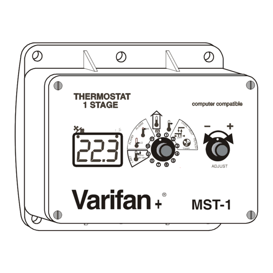
CHAPTER 3 - USER’S GUIDE CHAPTER 3 - USER’S GUIDE The MST-1 front panel shown above features a LED status window and two control dials which are respectively used to select a function and adjust a setting. LED STATUS WINDOW... - Page 18 When secondary functions 2 and 3, and 9 through 11 are selected the status window displays a blinking value along with a scrolling LED display. Selection of function 12 removes the MST-1 from the secondary function mode. Page 18 www,monitrol.com...
-
Page 19: Main Set Point Temperature
Adjustor dial counterclockwise to decrease temperature setting, clockwise to increase it. The main set point temperature is displayed on the MST-1. Note: The ramping feature (primary function 9) must be (OFF) to adjust the main set point. Page 19 www,monitrol.com... -
Page 20: Stage 1 Differential
MST-1 STAGE 1 DIFFERENTIAL In order to minimize erratic behavior of Heater / Fan 1 when ambient room temperature is exactly at the relative set point, the differential setting separates this ON / OFF threshold into two: one ON threshold and one OFF. This feature greatly reduces equipment wear. -
Page 21: Stage 1 Duty Cycle Timer
The duty cycle setting is displayed on the MST-1. Example: The period of Stage 1 is set to 8 min- utes by secondary function (3), while the duty cycle is set to 75%. When the temperature... -
Page 22: Ramping
Adjustor dial counterclockwise to decrease the ramping rate, clockwise to increase it. The ramping setting is displayed on the MST-1. NOTE: When ramping is activated or enabled, the main set point temperature cannot be manually adjusted. Ramping automatically turns OFF when the minimum temperature limit is reached! Example: The main set point temperature is set to 70°F... -
Page 23: Record Low Temperature
13.5°F is recorded, Lo is displayed. Viewing the lowest temperature recorded: • rotate the Selector dial to position (10) Clearing the low temperature value: • quickly rotate Adjustor dial counterclockwise, then clockwise. CLr will be briefly displayed on the MST-1. Page 23 www,monitrol.com... -
Page 24: Record High Temperature
105.0°F is recorded, Hi is displayed. Displaying highest temperature recorded: • rotate the Selector dial to position (11) Clearing the high temperature value: • quickly rotate Adjustor dial counterclockwise, then clockwise. CLr will be briefly displayed on the MST-1. Page 24 www,monitrol.com... -
Page 25: Ambient Room Temperature Display
105.0°F (41.0°C). If the temperature is lower than 41.0°F, Lo is displayed. If the temperature is higher than 105.0°F, Hi is displayed. Viewing the ambient temperature: • rotate the Selector dial to position (12) The ambient temperature is displayed on the MST-1. Page 25 www,monitrol.com... -
Page 26: Heating Or Cooling Mode
MST-1 HEATING OR COOLING MODE Select if the MST-1 operates in heating mode or cooling mode. The stage 1 (heating or cooling mode) is adjusted by selecting HE or COO. HEA on the display if you want to use the stage 1 in heating... -
Page 27: Duty Cycle Period
• rotate the Selector dial to position (3), • rotate the Adjustor dial counterclockwise to decrease the period, clockwise to increase The Stage 1 period setting is displayed on the MST-1. Page 27 www,monitrol.com... -
Page 28: Minimum Ramping
• rotate the Selector dial to position (9), • rotate the Adjustor dial counterclockwise to decrease the minimum ramping setting, clockwise to increase it. The minimum ramping setting is displayed on the MST-1. NOTE: When main point temperature reaches minimum... -
Page 29: Low Temperature Alarm
When a low temperature alarm occurs an alarm contact is activated and the alarm LED lights on the MST-1. Alarm The low temperature alarm is adjusted in 0.5 degree increments from a minimum setting of - 32.0°F (-18.0°C) to a maximum setting of 0.0°F... -
Page 30: High Temperature Alarm
When a high temperature alarm occurs an alarm contact is activated and the alarm LED lights on the MST-1. Alarm The high temperature alarm is adjusted in 0.5 degree increments from a minimum setting of 0°F (0°C) to a maximum setting of 32.0°F... -
Page 31: Appendix
APPENDIX TROUBLESHOOTING SYMPTOM CAUSE and REMEDY − Lo is ° Temperature is below minimum (13.5 F or continually ° -10.0 − displayed Probe is disconnected or defective. − Hi is Temperature above maximum continually (105.0°F or 41°C). − displayed Probe is short circuited. −... -
Page 32: Specifications
MST-1 SPECIFICATIONS DESCRIPTION VALUE − INPUT POWER − 115/230 VAC − 50 / 60 Hz − STAGE 1 (dry relay 10 A; 115V/230V − contact) 1/2 HP @ 115V − Fuse 10A 1 HP @ 230V − Min. Rating 10mA at 115V* −... -
Page 33: Record Form
APPENDIX RECORD FORM Dial Option Default setting User setting Main Set Point Temperature 77°F 25°C Stage 1 Differential 4°F 2°C Stage 1 Duty Cycle Timer 100% 100% Ramping 2nd Function Heating or cooling mode Duty cycle period 2min 2min Minimum Ramping Limit 65°F 18°C Lo Temperature Limit... - Page 34 MST-1 Page 34 www,monitrol.com...
- Page 35 WARRANTY Limited Warranty manufacturered equipment supplied components have gone through rigorous inspection to assure optimal quality of product and reliability. Individual controls are factory tested under load, however the possibility of equipment failure and/or malfunction may still exist. For service, contact your local retailer or supplier. The warranty period shall be for two years from manufacturing date.
- Page 36 MAV MST-1M Ver: 1.02 November 20, 2012 www,monitrol.com...
Need help?
Do you have a question about the MST-1 and is the answer not in the manual?
Questions and answers