
Subscribe to Our Youtube Channel
Related Manuals for Varifan MST-5

Summary of Contents for Varifan MST-5
- Page 1 MST-5 USER’S MANUAL 5 STAGE THERMOSTAT computer compatible 2 3 4 5 TIMER reduc. per day ADJUST Varifan ® MST-5 www.monitrol.com...
- Page 2 MST 5 Although the manufacturer has made every effort to ensure the accuracy of the information contained herein, this document is subject to change without notice due to ongoing product development. WARNING AND PRECAUTIONS Equipment , probe failure, blown fuses and/or tripped breakers may prove harmful to the contents of the building.
-
Page 3: Table Of Contents
TABLE OF CONTENTS CHAPTER 1 - INTRODUCTION General ................5 Description ............... 5 Definition of terms ................ 7 CHAPTER 2 - INSTALLATION Unpacking ................ 9 Mounting ................. 9 Switch Settings ............... 10 2.3.1 Line Voltage Selector Switch .......... 10 2.3.2 Software Settings Switch .......... - Page 4 MST 5 CONTENTS CONTINUED... Stage 5 Relative Set Point ..........26 Differential Cool Stages ..........27 Differential Heat Stage ..........28 Ramping ................. 29 Record Low Temperature ..........30 Record High Temperature ..........31 Ambient Room Display ........... 32 SECONDARY FUNCTIONS Stage 1 Duty Cycle Period ..........
-
Page 5: Chapter 1 - Introduction
CHAPTER 1 - INTRODUCTION 1. GENERAL This document provides a description of the MST-5 control panel. This document is organized as follows: • Introduction • Installation • User’s Guide • Appendix 1.1 DESCRIPTION Congratulations on the purchase of your MST-5 Multistage Thermostat. - Page 6 The fifth stage controls another heater for colder climates or an other single speed fan. The MST-5 provides you with full control over all five stages via the use of an easy to follow display panel. All programmable features can be customized to meet your requirements.
-
Page 7: Definition Of Terms
DEFINITION OF TERMS MAIN SET POINT The desired room temperature. Other temperature settings on the MST-5 are relative to the main set point temperature. RELATIVE TEMPERATURE A value added to or subtracted from the main set point which results in a new temperature at which a desired action starts or stops. - Page 8 MST 5 Page 8 www.monitrol.com...
-
Page 9: Chapter 2 - Installation
Make sure the unit is mounted right, side up with the cable entry holes facing down. The MST-5 will operate in a temperature range of 32°F to 120 °F (0 °C to 50 °C). The enclosure is watertight, but it is not splash proof or immersion proof. -
Page 10: Switch Settings
Mounting hardware is not shipped with the unit. Install mounting screw on wall and hang the unit in place by sliding the rear mounting hole of the MST-5 over the screw. Use two more screws to secure the MST-5 in place using the bottom mounting hole. -
Page 11: Connection Procedure
2.4.1 - Input power Use a screwdriver to remove cable knock-outs for the installation of cabling to the MST-5. Do not apply power to the MST-5 and all loads until all connections have been completed! 2.4.1.1 - 115 VAC Make certain that the line voltage selector switch is set to 115 VAC. -
Page 12: Temperature Probe
Refer to figure 4. 2.6 ALARM The MST-5 provides a normally open and normally closed dry contact for alarming low or high temperature conditions. In addition, that same contact may be used to signal a power failure. -
Page 13: Powering Up
CHAPTER 2 - INSTALLATION 2.7 POWERING UP Before powering up the MST-5, attach the faceplate to the casing of the MST-5 using the six screws previously removed. Set Selector knob to position (12). Upon powering up, the unit will test it’s display by briefly lighting all the segments of it’s LED display. - Page 14 MST 5 Fig. 2 Wiring diagram for 2 double speed fans and 1 heating unit. Notes for Figures 1 and 2. Power cut and protection devices in case of overload. Connect the grounding wire to the ground terminal 13. IMPORTANT Must be on a 15A separate circuit of the MST.
- Page 15 CHAPTER 2 - INSTALLATION Fig. 3. Probes and alarm wiring. Fig. 4 Temperature average probe connection. Page 15 www.monitrol.com...
- Page 16 MST 5 Fig. 5 Main (bottom) Board: terminal blocks and ground connection. Page 16 www.monitrol.com...
-
Page 17: Chapter 3 - User Guide
CHAPTER 3 - USER’S GUIDE CHAPTER 3 USER’S GUIDE Page 17 www.monitrol.com... - Page 18 MST 5 Page 18 www.monitrol.com...
-
Page 19: Led Status Window
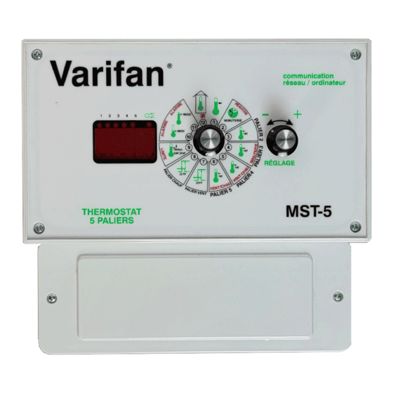
CHAPTER 3 - USER’S GUIDE The MST 5 front panel shown above features a LED status window control dials which respectively used to select a function and adjust a setting. LED STATUS WINDOW The LED status window features a 3 digit LED display for temperature in Fahrenheit or Celsius, and programmable settings. - Page 20 MST 5 The 12 primary functions are: • 1 Main set point temperature • 2 Stage 1 duty cycle timer • 3 Stage 2 relative set point • 4 Stage 3 relative set point • 5 Stage 4 relative set point •...
-
Page 21: Main Set Point Temperature
Adjuster dial counterclockwise to decrease the temperature setting, and clockwise to increase it. The main set point temperature is displayed on the MST-5. Note: The ramping feature (primary function 9) must be (OFF) to adjust the main set point. -
Page 22: Stage 1 Duty Cycle Timer
The duty cycle is displayed on the MST-5. Example: The period of stage 1 is set to 8 minutes by secondary function (2), while the duty cycle is set to 25%. -
Page 23: Stage 2 Relative Set Point
The stage 2 relative set point is displayed on the MST-5. If a 2 speed motors is used, stage 1 shuts off when stage 2 begins to operate. Example: A main set point of 70°F along with a stage 2 relative set point of 2°F is... -
Page 24: Stage 3 Relative Set Point
The stage 3 relative set point is displayed on the MST-5. Example: A main set point of 70°F along with a Stage 3 relative set point of 4°F is selected. When the temperature of the room reaches 74°F, Stage 3 begins to... -
Page 25: Stage 4 Relative Set Point
The stage 4 relative set point is displayed MST-5. If a 2 speed motors is used, stage 3 shuts off when stage 4 begins to operate. Example: The main set point temperature is adjusted to 70°F. -
Page 26: Stage 5 Relative Set Point
The stage 5 relative set point is displayed MST-5. Example: The main set point temperature is adjusted to 70°F. A heater is in use and the relative set point is adjusted to -4°F. -
Page 27: Differential Cool Stages
Adjusting the differential for cool stage setting: • rotate the selector dial to position (7), • rotate the adjuster dial counterclockwise to decrease the differential setting, and clockwise to increase it. The differential setting is displayed on the MST-5. Page 27 www.monitrol.com... -
Page 28: Differential Heat Stage
Adjusting the differential for heat stage setting: • rotate the selector dial to position (8), • rotate the adjuster dial counterclockwise to decrease the differential setting, and clockwise to increase it. The differential setting is displayed on the MST-5. Page 28 www.monitrol.com... -
Page 29: Ramping
CHAPTER 3 - USER’S GUIDE RAMPING The ramping function automatically reduces the main set point by the set value every 24 hours. The ramping setting is adjusted in 0.01 degree decrements from a minimum setting of OFF, - 0.01°F (-0.01°C) to a maximum setting of - 0.99°F (-0.50°C). -
Page 30: Record Low Temperature
13.5°F is recorded, Lo is displayed. Viewing the lowest temperature recorded: • rotate the selector dial to position (10) Clearing the low temperature value • quickly rotate adjuster dial counterclockwise, then clockwise. CLr will be briefly displayed on the MST-5. Page 30 www.monitrol.com... -
Page 31: Record High Temperature
105.0°F is recorded, Hi is displayed. Displaying highest temperature recorded: • rotate the selector dial to position (11) Clearing the high temperature value • quickly rotate adjuster dial counterclockwise, then clockwise. CLr will be briefly displayed on the MST-5. Page 31 www.monitrol.com... -
Page 32: Ambient Room Display
(41.0°C). If the temperature is lower than 13.5° F, Lo is displayed. If the temperature is higher than 105.0°F, Hi is displayed. Viewing the room temperature: • rotate the selector dial to position (12) Room temperature is displayed on the MST-5. Page 32 www.monitrol.com... -
Page 33: Stage 1 Duty Cycle Period
• rotate the selector dial to position (2), • rotate the adjuster dial counterclockwise to decrease the period, and clockwise to increase it. The stage 1 period setting is displayed on the MST-5. Page 33 www.monitrol.com... -
Page 34: Drip Cool Duty Cycle
The duty cycle setting is displayed on the MST-5. Example: The duty cycle is set to 25%. When room temperature rises above the relative set point the drip cool units operates for 3 minutes, and go OFF for 9 minutes. -
Page 35: Stage 4 Heating Or Cooling Mode
The heating or cooling mode is displayed on the MST-5. If stage 4 is set for a 2 speed motor, it is not possible to adjust this stage in heating mode. -
Page 36: Stage 5 Heating Or Cooling Mode
(6), • rotate the adjuster dial counterclockwise to set the stage in heating mode, and clockwise to to set it in cooling mode. The heating or cooling mode is displayed on the MST-5. Page 36 www.monitrol.com... -
Page 37: Minimum Ramping
• rotate the Selector dial to position (9), • rotate the Adjuster dial counterclockwise to decrease the minimum ramping setting, clockwise to increase it. The minimum ramping setting is displayed on the MST-5. NOTE: When main point temperature reaches minimum... -
Page 38: Low Temperature Alarm
• rotate the selector dial to position (10), • rotate the adjuster dial counterclockwise to decrease the setting, and clockwise to increase it. The low temperature alarm setting is displayed on the MST-5. Page 38 www.monitrol.com... -
Page 39: High Temperature Alarm
• rotate the selector dial to position (11), • rotate the adjuster dial counterclockwise to decrease the setting, and clockwise to increase it. high temperature alarm setting displayed on the MST-5. Page 39 www.monitrol.com... -
Page 40: Troubleshooting
MST 5 TROUBLESHOOTING SYMPTOM CAUSE and REMEDY − Lo is ° Temperature is below minimum (13.5 continually ° or -10.0 displayed − Probe is disconnected or defective. − Hi is Temperature above maximum continually (105.0°F or 41°C). displayed − Probe is short circuited. −... -
Page 41: Specifications
APPENDIX SPECIFICATIONS DESCRIPTION VALUE − INPUT POWER 12 W − 115/230 -20%, +10% VAC − 50 / 60 Hz STAGE 1 (dry relay − 10 AMP ; 115V/230V contact) − 1/2 HP @ 115V Not Fused − 1 HP @ 230V −... -
Page 42: Record Form
MST 5 RECORD FORM Dial Option Default setting User setting Main Set Point Temperature 77°F 25°C Stage 1 Duty Cycle Timer Stage 2 Relative Set Point 4°F 2°C Stage 3 Relative Set Point 6°F 3°C Stage 4 Relative Set Point 8°F 4°C Stage 5 Relative Set Point... - Page 43 WARRANTY Limited Warranty manufactured equipment supplied components have gone through rigorous inspection to assure optimal quality of product and reliability. Individual controls are factory tested under load, however the possibility of equipment failure and/or malfunction may still exist. For service, contact your local retailer or supplier. The warranty period shall be for two years from manufacturing date.
- Page 44 MAV MST-5M Ver: 1.1 October 1995 Rev. July 1997 Rev.June 2001 www.monitrol.com...
Need help?
Do you have a question about the MST-5 and is the answer not in the manual?
Questions and answers