Table of Contents
Advertisement
Quick Links
Advertisement
Table of Contents

Related Manuals for Cerasonar CS-2000DSP4

Summary of Contents for Cerasonar CS-2000DSP4
- Page 1 Network DSP Power Amplifier User Manual cerasonar.de...
-
Page 2: Table Of Contents
4.11.1 FIR filter and applications ..................- 22 - 4.11.2 Using third party software to adjust FIR magnitude and phase ......- 24 - 4.11.3 Using FIR DESIGNER in Cerasonar to adjust FIR magnitude and phase ....- 29 - 4.11.3.a FIR DESIGNER - Import ..................- 31 - 4.11.3.b FIR DESIGNER - FIR-EQ ..................- 31 -... -
Page 3: Chapter 1: Introduction
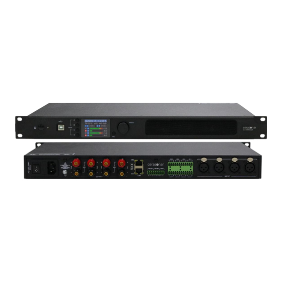
Support mode: stereo, bridge, mono, free matrix. Support Constant Pressure and Resistance: 100V, 70V, 8Ω, 4Ω. Colourful IPS display. Nice GUI control software Cerasonar (PC windows). USB free driver connecting, support TCP/IP, RS232, RS485, GPIO connections. Remote on/off amplifier. - Page 4 Input Balanced 4 x XLR; 4 x Phoenix terminal Input topology 4 x Phoenix terminal line out Output 4 x Binding post Dante 4 channels input Operating mode Stereo / Bridge / Parallel /Matrix Control TCP/IP, USB, RS485, RS232 POWER Channels Power@8Ω...
-
Page 5: Chapter 3: Functional Structure
Limiter, high temperature, DC, high frequency, short circuit, back electromotive force, peak current limiter, Protection surge current limiter, start delay, power breaker protection, power supply over-voltage/ under-voltage protection ELECTRICAL AND PHYSICAL Display 320 x 240 pixel, IPS colourful Power supply AC100 to 240 50/60Hz Device 483mm*305mm*44.5mm Dimension... -
Page 6: Description Of Display
3.1 Description of display Main interface In IPS display, user can learn status of this power amplifier, such as device name, temperature, mute status, gain level, current preset, volume, operating mode. When locked, long press 2 seconds to unlock. Main Software control Compress/limiter start Menu interface... -
Page 7: Chapter 4: Operation Of Control Software - Cerasonar
Operating mode Chapter 4: Operation of control software - Cerasonar Cerasonar provides user with a fast interaction to control one or more devices through multiple methods: TCP/IP, USB, common serial port (RS232/485). Easily set DSP functions of device, GPIO control and inquire central control codes.The configuration parameter can be stored in presets, convenient for various applications. -
Page 8: Connections Setting
Windows, no need to setup. Double click Cerasonar.exe, the main interface will pop up. 4.2 Connections setting If connect device by using Setting network cable, click Device List, choose TCP in Connection windows. - Page 9 If connect device by using USB Setting A-B, click in Device List, choose USB Connection windows. If connect device by using network cable, click Setting Device List, choose COM in Connection windows. Please check port and baud rate carefully for 232 or 485 before setting.
- Page 10 When using TCP control, there is a situation that only one point displayed after scanning, but can not connect device. In this case, user need to change the IP address of the device to the same network segment as the PC computer.
-
Page 11: Dsp Functions Setting
User can link multiple same devices in group by clicking Link button, and then set group device, group name and main device, link mode and parameter according to needs. 4.3 DSP functions setting Double-click HOME icon to open all functional interfaces, or double-click a function icon separately to open the corresponding interface. -
Page 12: Dsp Functions Setting - Input
4.3.1 DSP functions setting - INPUT Set source of each channel; Set sensitivity of each channel 0/6/12dBu; Set gains, phase or mute in each channel; When choosing test signal, user can select Sine/Pink Noise/White Noise for each input channel. - 10 -... -
Page 13: Dsp Functions Setting - Noise Gate
4.3.2 DSP functions setting - NOISE GATE Attack: 1 to 2895ms; Release: 1 to 2895ms; Threshold: -120 to 0dBu; Click to enable this function. 4.3.3 DSP functions setting - PEQ-X (input and output) High pass filter enter value of frequency and select type, press to enable this function: Butterworth 6/12/18/24/36/48, Bessel 12/24/36/48, Linkwitz-Riley 12/24/36/48. - Page 14 Freq(Hz) Q Gain(dB): input value or use mouse pulley to set value; Users can also drag the frequency dot on the curve to adjust. PEQ 10 bands for output channel Type: PEQ/LSLV/HSLV/ALLPASS-1/ALLPASS-2; Freq(Hz) Q Gain(dB): input value or use mouse pulley to set value; Users can also drag the frequency dot on the curve to adjust.
-
Page 15: Dsp Functions Setting - Delay (Input And Output)
4.3.4 DSP functions setting - DELAY (input and output) Max 100ms for input channel; Max 20ms for output channel; Click to enable this function; Click to reset each channel; User switch ft/cm/ms measurement for delay. 4.3.5 DSP functions setting - MATRIX MIX In the above figure, input channel (on top side) corresponds to the output channel. -
Page 16: Dsp Functions Setting - Compressor
4.3.6 DSP functions setting - COMPRESSOR Soft knee: 0 to 30; Threshold: -90 to 21 dB; Attack: 1 to 2895 ms; Ratio: 1 to 100; Release: 1 to 2895 ms; Click to enable this function; ... -
Page 17: Monitoring And Setting Of Channels
4.4 Monitoring and setting of channels User can monitor gains level of input and output channels. 4.4.1 Channel gain level There are two kinds of input signal in some products: ANALOG, DANTE network audio. It will show a label for user. Input value, drag gain fader or use mouse pulley to set value of gain. -
Page 18: Group And Channels Link
4.4.3 Group and channels link User can quickly set channels in groups for opening or closing mute, phase, noise gate, PEQ and delay function. M Mute M Mute + Phase E PEQ N Noise Gate D Delay E PEQ C Compressor D Delay L Limiter + Phase... -
Page 19: Menu - File
Channel copy: copy device input and output channel parameter, can realize cross-device copy parameter (Note: the same type of device is required). Central control and GPIO: Cerasonar provides user a quickly way to inquiry code of Center Control and GPIO setting. More details, please refer to another user manual <GPIO And Center Control Code User Manual>, it provides whole... -
Page 20: Menu - Camera (Only Available In Dsp Matrix Products)
4.7 Menu - Camera (only available in DSP matrix products) 4.7.1 Camera setting Generally, the camera position should be debugged before the tracking starts, - 18 -... -
Page 21: Set Camera Tracking
and finally the parameter of this part are saved on the camera. 1. Set the serial ports via RS232 or RS485. 2. Set the camera address and protocol type refer to the protocol depends on the camera model. 3. The preset No. is defined by the user for the camera, and then adjust the up, down, left, right, focal length, aperture and other parameter. -
Page 22: Set Mic Tracking
4.7.3 Set Mic Tracking Mic No.: corresponds to the input channel of device. (parameter need to be set separately for each channel) Priority: Higher number for priority. If the priorities are the same, the processing is performed in the sequence of triggering priorities. If two mics speak at the same time, the camera automatically rotates to the preset position corresponding to the mic with a higher priority or sends the command corresponding to the mic with a higher priority. -
Page 23: Menu - Preset
4.9 Menu - Preset Save: select the saved gear, save all the parameter of the current automatic gear of the machine to the device preset (2~30 Preset bit). Recall: call the device preset to the current automatic gear position. Delete: delete the existing preset, the default file cannot be deleted, over written or saved. -
Page 24: Menu - System
4.10 Menu - System Language: multi-language switching, supports ENGLISH. About: current control software and device firmware version information. Upgrade: use can upgrade the firmware by using this function, a upgrade .bin file should be needed from seller or speaker factory. In general, no need to upgrade the firmware in device. - Page 25 Frequency division optimization to improve the consistency of frequency response of multi-division speakers over their coverage Angle range. Devices required: Measurement ×1 Microphone Audio Interface ×1 Windows PC ×1 (installed software including Smaart, rePhase or FIR Designer, Cerasonar) - 23 -...
-
Page 26: Using Third Party Software To Adjust Fir Magnitude And Phase
FIR audio processor or ×1 DSP network power amplifier Speaker ×1 Connection schematic diagram: 4.11.2 Using third party software to adjust FIR magnitude and phase Step 1: measure phase curve of speaker in Smaart V7 - 24 -... - Page 27 Step 2: copy curve to ASCII in Smaart V7 Step 3: copy curve to software rePhase or Cerasonar FIR DESIGNER “Import Measurement From Clipboard” - 25 -...
- Page 28 Step 4: adjust phase EQ or any other parameter in software, to match a linear phase for speaker - 26 -...
- Page 29 Step 6: import FIR .txt file in FIR audio processor or DSP network power amplifier Open Cerasonar software, user can choose an input channel or output channel as needed, such as FIR in output channel, it will show a FIR function window.
- Page 30 press IMPORT to import txt. file, than press STORE to effect this importing. remember to cancel BYPASS. - 28 -...
-
Page 31: Using Fir Designer In Cerasonar To Adjust Fir Magnitude And Phase
Step 8: measure the curve of speaker again, use can find it become more linear. After all setting, please remember to save a preset for your hard working in the speaker. 4.11.3 Using FIR DESIGNER in Cerasonar to adjust FIR magnitude and phase Beside using third party software, Cerasonar provides user a more convenient way to adjust FIR magnitude and phase of each channels. - Page 32 Click “FIR” - “Designer” button to enter FIR automatic linear magnitude and phase function interface. Or click “FIR DESIGNER” in main interface to enter FIR automatic linear magnitude and phase function interface, which can quickly help user return to the page he set last time. Let’s begin to set: - 30 -...
-
Page 33: Fir Designer - Import
4.11.3.a FIR DESIGNER - Import Load: load speaker measurement file from Smaart, usually it’s a .txt file. Import Clipboard: load ASCII data directly from Smaart. Clear: clear measurement data. Normalise magnitude to max or Magnitude offset (dB): this can help user to adjust a certain dB of magnitude, in order to adjust magnitude curve as little as possible. -
Page 34: Fir Designer - Magnitude Correction And Phase Correction
bands of PEQ \ LSLV \ HSLV to adjust magnitude. Try to set a linear magnitude of target speaker. Mark: changing FIR magnitude doesn’t effect its phase. 4.11.3.c FIR DESIGNER - Magnitude Correction and Phase Correction Of course, if there are too many speakers to be adjust, user has to spend a long time manually adjusting their magnitude. -
Page 35: Fir Designer - Generate
4.11.3.d FIR DESIGNER - Generate Select Taps (such as 512) of this adjustment, and store it in a FIR channel. User can also name this FIR adjustment and export it to a .KF file. After finish all setting, return back to FIR interface. Cancel BYPASS button to make it work. - 33 -... -
Page 36: Chapter 5: Connect With 12V Trigger
Chapter 5: Connect with 12V trigger Cerasonar cs-2000dsp4 offers standby operating by connecting with 12V trigger: “12V trigger”, for smooth operation we recommend integration via the 12V trigger, this is present in high-quality AV receivers or audio streaming devices and switches the cs-2000dsp4 on and off.