EnerSys Alpha Cordex CXC HP Software Manual
Hide thumbs
Also See for Alpha Cordex CXC HP:
- Integrator manual (48 pages) ,
- Software manual (319 pages)

Related Manuals for EnerSys Alpha Cordex CXC HP


Summary of Contents for EnerSys Alpha Cordex CXC HP
- Page 1 Cordex® CXC HP Controller Software Manual User Guide ID: 0350058-J0 Effective: 01/2023 Read this document carefully. Learn how to protect your equipment from damage and fully understand its functions.
- Page 2 Copyright notice © 2023 Alpha Technologies Ltd., an EnerSys company. All Rights Reserved. Trademarks and logos are the property of EnerSys and its affiliates. Subject to revisions without prior notice. E.&O.E. No part of this documentation shall be reproduced, stored in a retrieval system, translated, transcribed, or transmitted in any form or by any means manual, electric, electronic, electromechanical, chemical, optical, or otherwise without prior explicit written permission from Alpha Technologies Ltd.
-
Page 3: Table Of Contents
Contents List of Figures............................. 14 List of Tables...............................16 1. Safety..............................17 2. Software release history........................20 2.1. Application release 8.00.......................20 2.2. Application release 7.40.......................20 2.3. Application release 7.30.......................21 2.4. Application release 7.20.......................21 2.5. Application release 7.10.......................22 2.6. Application release 7.01.......................22 2.7. Application release 7.00.......................22 2.8. Application release 6.30.......................23 2.9. Application release 6.20.......................23 2.10. Application release 6.10......................23 2.11. Application release 6.00......................24 2.12. Application release 5.20......................24 2.13. Application release 5.10......................25 2.14. Application release 5.01......................25 2.15. Application release 5.00......................26 2.16. OS release 6.30......................... 26 2.17. OS release 6.20......................... 26 2.18. ... - Page 4 Cordex® CXC HP Controller Software Manual 3.2.2. Watchdog alarm......................... 33 3.2.3. Typical system configuration....................33 3.2.4. How to get help......................... 34 4. Getting started............................36 4.1. Apply power..........................36 4.2. Connect to the controller......................36 4.2.1. In-shelf controller........................38 4.3. Navigating the controller user interface..................38 4.3.1. Log into the controller......................38 4.3.2. Controller menu........................39 4.3.3. Overview of the LCD......................40 4.3.4. Overview of the web interface................... 49 4.3.5. Overview of the in-shelf display..................58 4.4. Email notification.......................... 59 4.5. Setup SNMP communication....................... 62 4.6. Setting up Modbus communication....................63 4.7. Setup syslog communication.......................
- Page 5 Cordex® CXC HP Controller Software Manual 5.3.2. Create a DC system......................81 5.3.3. Configure basic DC system settings..................82 5.3.4. Configure dynamic thresholds for output voltage alarms..........82 5.3.5. Configure the rectifiers.......................82 5.3.6. Configure the shunts......................83 5.3.7. Configure the system loads....................84 5.3.8. Configure the current transducer..................85 5.3.9. Configure the general purpose transducer................ 85 5.3.10. Configure the system disconnects...................86 5.3.11. Configure lead acid or NiCad battery parameters............87 5.3.12. Configure Polarium battery parameters................90 5.3.13. Configure the battery temperature sensors..............91 5.3.14. Configure the charging system function................92 5.3.15. Configure the temperature compensation system function..........93 5.3.16. Configure battery runtime and health estimation.............94 5.3.17. Run a manual battery test....................94 5.3.18. Configure power save...................... 95 5.4. Connect to other systems......................95 5.4.1. Represent a converter system as a DC load..............96 5.4.2. Represent an inverter system as a DC load..............96 6. Converter systems..........................98 6.1. Introduction to converter systems....................98 6.2. Creating a converter system......................99 6.2.1. Creating a system from a configuration file..............
- Page 6 Cordex® CXC HP Controller Software Manual 7.1.4. Live alerts.........................106 7.1.5. System functions......................106 7.2. Create an inverter system......................107 7.2.1. Create a system from a configuration file................107 7.3. Assign a T2S module.........................108 7.4. Commission an inverter system....................108 7.5. Configure the T2S inverter controller..................110 7.6. Configure the inverters.......................110 7.7. Configure the bypass switch......................110 7.7.1. Configure a basic bypass switch..................111 7.7.2. Configure an XMBS bypass switch................. 111 7.8. Configure the breaker or fuse....................112 8. Line power systems...........................113 8.1. Introduction to line power systems.................... 113 8.1.1. Components of a line power system................113 8.1.2. Quick reference for configuring a line power system............115 8.2. Create a line power system....................... 115 8.2.1. Create a system from a configuration file................116 8.3. Configure the line power modules..................... 116 8.3.1. Shared alarm configuration....................116 8.4. Line power module alarms......................117 8.5. Configure the line power system channels................117 8.6. Configure the line power system loads..................117 8.7. Line power system layout......................118 8.7.1. Use the layout screen to view module status..............118 8.7.2. Use the layout screen to view load status...............119 8.7.3. Use the layout screen to assign channels to loads............
- Page 7 Cordex® CXC HP Controller Software Manual 9.1. Introduction to auxiliary systems....................125 9.2. Create an auxiliary system......................125 9.2.1. Create a system from a configuration file................125 9.3. Current transducers........................125 9.4. Configure the current transducer....................125 9.5. Configure the general purpose transducer................126 10. Distribution systems........................127 10.1. Introduction to distribution systems..................127 10.2. Create a distribution system....................128 10.2.1. Create a system from a configuration file..............128 10.3. Distribution subsystems......................128 10.4. Create a smart subsystem.......................129 10.5. Create a user defined subsystem....................130 10.6. Configure the panel details...................... 131 10.7. Configure the breaker or fuse details..................132 10.8. The subsystem layout......................133 10.9. Map shunts to ADIO module inputs..................133 11. DC source systems.......................... 135 11.1. Create a DC source system.....................135 11.2. Create and configure a DC source..................135 11.3. DC source system effect on other systems................136 12. AC source systems..........................137 12.1. Create an AC source system....................137 12.2. Create an AC source.......................
- Page 8 Cordex® CXC HP Controller Software Manual 13.8.1. Introduction to Matrix C16™ high density connectorized DC distribution breaker panel............................144 13.8.2. Matrix C16™ high density connectorized DC distribution breaker panel in a CXPS-HSS Hyperboost system........................144 14. Generator............................145 14.1. Create an AC generator......................145 14.2. Create a DC generator......................146 14.3. Configure the generator......................146 14.4. Start and stop conditions......................147 14.4.1. Default start and stop conditions................... 147 14.4.2. Add start and stop conditions..................147 14.4.3. Adding complex start and stop conditions..............148 14.4.4. Testing start and stop conditions................... 148 14.4.5. Example: Start and stop the generator on a schedule..........148 14.5. Start and stop logic........................149 14.5.1. Start logic........................150 14.5.2. Stop logic........................150 14.6. Generator state........................151 14.7. ...
- Page 9 Cordex® CXC HP Controller Software Manual 16.7. Alarms and alerts........................159 16.7.1. Thermal controller module alert to thermal system alarm propagation......159 16.7.2. Identifying the origin of an active alarm.................159 16.7.3. Alarms where hardware does not exist................. 160 17. Controller redundancy........................161 18. Power flow............................162 18.1. Introduction to power flow......................162 18.2. Access power flow........................162 18.2.1. Getting help........................162 18.2.2. Use power flow configuration suggestions..............163 18.2.3. Configure the default power flow................... 163 18.3. Interact with power flow......................163 18.4. Controller power flow....................... 164 18.5. Power flow for systems managed by different controllers............165 19. Maintaining the system........................167 19.1. Rectifier maintenance.......................167 19.1.1. Rectifier alarms......................167 19.1.2. Insert unassigned modules.................... 167 19.2. Inverter and T2S system maintenance..................167 19.2.1. Maintenance bypass......................
- Page 10 Cordex® CXC HP Controller Software Manual 19.5. Low voltage disconnect (LVD) maintenance................177 20. Maintaining the controller....................... 179 20.1. Ethernet communications......................179 20.1.1. Connect via the web interface..................180 20.2. Working with alarms, alerts, and hints..................180 20.2.1. Active alarms........................180 20.2.2. Alerts..........................181 20.2.3. Hints..........................181 20.2.4. Alarm cut-off (ALCO)..................... 182 20.2.5. Alarm activation delay at startup................... 182 20.2.6. Alarm summary relays....................183 20.2.7. Create user alarms......................183 20.3. Controller maintenance......................184 20.3.1. Restart the controller......................184 20.3.2. Restart the controller via the LCD................. 185 20.3.3. Powering down the controller..................185 20.3.4. Change the time and date..................... 186 20.3.5. Change the language for the LCD................186 20.3.6. Change the language for the web interface..............186 20.3.7. Change user interface strings..................187 20.3.8. Change the web session language................
- Page 11 Cordex® CXC HP Controller Software Manual 20.5.3. Upgrade the controller software..................199 20.5.4. Export a configuration file....................200 20.5.5. Import a configuration file....................201 20.5.6. Configuration restore points...................204 20.5.7. Export diagnostic information..................205 20.5.8. License key........................206 20.5.9. Upload the software manual..................207 20.5.10. Export inventory file..................... 208 20.5.11. Backup and restore...................... 209 20.6. User account maintenance...................... 210 20.6.1. Set up users and permissions..................210 20.6.2. Edit user permissions.....................210 20.6.3. Enable new users......................211 20.6.4. Disable users......................... 211 20.6.5. Changing the default password from the LCD.............. 212 20.6.6. Changing the default password from the web interface..........212 20.6.7. User account password requirements................212 20.6.8. Machine user........................213 20.6.9. Remote configuration lockout..................213 20.7. Remote authentication......................
- Page 12 Cordex® CXC HP Controller Software Manual 21.1.3. Calibrate analog inputs....................224 21.1.4. Calibrate shunts, current transducers, and temperature probes........228 21.1.5. Test relays........................230 21.1.6. Test comms lost action....................230 21.1.7. Enable temperature sensor failure alarms..............230 21.1.8. Ground fault detection....................231 21.2. Module firmware upgrades.......................231 21.2.1. Module firmware upgrade....................231 21.2.2. Upload a firmware file....................231 21.2.3. Select the file to upgrade....................232 21.2.4. Upgrade the module...................... 232 22. Using custom views, data, timers, counters, scheduler, and custom actions......234 22.1. Custom views........................... 234 22.1.1. Create custom views..................... 234 22.1.2. Add components in the custom view................234 22.1.3. Access and configure the default custom dashboard view..........236 22.1.4. Access the custom data view..................236 22.1.5. Remove a table from the custom view................
- Page 13 Cordex® CXC HP Controller Software Manual 22.5.1. Configure a recurring action..................250 22.6. Configure a one-time action.....................250 22.7. Configure scheduled actions....................250 22.8. Scheduled time spans......................251 22.9. Custom actions.........................251 22.9.1. Configure a change relay action..................251 22.9.2. Configure a change field to constant action..............252 22.9.3. Configure a change field to variable action..............253 23. Troubleshooting..........................255 23.1. Troubleshoot the controller...................... 255 23.1.1. No communication......................255 23.1.2. Unable to communicate via ethernet................255 23.1.3. Home button or LCD screen not responding..............256 23.1.4. Controller fail........................256 23.2. Troubleshoot a rectifier system....................257 23.2.1. Relays not triggered during alarm conditions..............257 23.2.2. Rectifier alarms and alerts..................... 257 23.2.3. Rectifier not acquired..................... 258 23.2.4. Rectifier communication lost..................258 23.2.5. Replacing a defective rectifier..................258 23.2.6. Using extended ranges....................259 23.2.7. Rectifier configuration error....................260 23.2.8. Rediscovering CAN devices..................
- Page 14 Cordex® CXC HP Controller Software Manual 23.4.2. Fan tray alarms......................265 23.4.3. Line power system overload..................266 23.4.4. Line power system transient events................266 23.4.5. Line power channels file import errors................266 24. Cordex® CXC HP controller reference guide................269 24.1. CAN modules........................... 269 24.2. Communication ports....................... 271 24.2.1. Ethernet ports.........................271 24.2.2. USB ports........................271 24.2.3. CAN ports........................272 24.3. Default system values and ranges..................273 24.3.1. 12 volt system default values and ranges..............273 24.3.2. 24 volt system default values and ranges..............274 24.3.3. 48 volt system default values and ranges..............275 24.3.4. 125 volt system default values and ranges..............276 24.3.5. 220 volt system default values and ranges..............
-
Page 15: List Of Figures
Cordex® CXC HP Controller Software Manual List of Figures Figure 3-1 Cordex® CXC HP controller (2RU model)................32 Figure 3-2 Typical DC system configuration....................34 Figure 3-3 Accessing Help on the LCD interface..................34 Figure 3-4 Accessing Help on the web interface..................35 Figure 3-5 Accounts and shortcuts ......................35 Figure 4-1 Menu structure..........................40 Figure 4-2 Controller LCD dashboard .......................41 Figure ... - Page 16 Cordex® CXC HP Controller Software Manual Figure 5-2 Temperature compensation voltage graph................71 Figure 5-3 Example of a DC system......................78 Figure 5-4 Quick reference for configuring a DC system................80 Figure 6-1 Example converter system....................... 98 Figure 6-2 Quick reference for configuring a converter system..............99 Figure 7-1 Single T2S inverter system components ................104 Figure 7-2 Quick reference for configuring an inverter system ...............105 Figure ...
-
Page 17: List Of Tables
Cordex® CXC HP Controller Software Manual List of Tables Table 4-1 In-shelf controller full menu......................59 Table 4-2 Email notification features......................60 Table 4-3 Email configuration........................62 Table 4-4 Controller alarm priorities to Syslog severities mapping table........... 65 Table 14-1 Default start and stop conditions when a DC system and battery are present.......147 Table 14-2 Default start and stop conditions when a DC system is present without a battery....147 Table 21-1 ADIO input calibration modes....................224 Table ... -
Page 18: Safety
1. Safety SAVE THESE INSTRUCTIONS: This document contains important safety instructions that must be followed during the installation, servicing, and maintenance of the product. Keep it in a safe place. Review the drawings and illustrations contained in this document before proceeding. If there are any questions regarding the safe installation or operation of this product, contact Alpha Technologies Ltd. or the nearest Alpha® power system representative. Safety wording and symbols To reduce the risk of injury or death, and to ensure the continued safe operation of this product, the following symbols have been placed throughout this document. Where these symbols appear, use extra care and attention. Attention: The use of attention indicates specific regulatory or code requirements that may affect the placement of equipment or installation procedures. Notice: Notices provide additional information to help complete a specific task or procedure. Important: Follow the prescribed procedures to avoid equipment damage or service interruption. - Page 19 Cordex® CXC HP Controller Software Manual | 1 - Safety Electrical safety Warning: Hazardous voltages are present at the input of power systems. The DC output from some rectifiers and batteries can have high voltage and high short-circuit current capacity that may cause severe burns and electrical arcing. Before working with any live battery or power system, follow these precautions: •...
- Page 20 Cordex® CXC HP Controller Software Manual | 1 - Safety Battery safety • Never transport an enclosure with batteries installed. Batteries must only be installed after the enclosure has been securely set in place at its permanent installation location. Transporting the unit with batteries installed may cause a short circuit, fire, explosion, or damage to the battery pack, enclosure, and installed equipment. • Servicing and connection of batteries must be performed by, or under the direct supervision of, personnel knowledgeable of batteries and the required safety precautions. • Batteries contain or emit chemicals known to cause cancer and birth defects or other reproductive harm. Battery post terminals and related accessories contain lead and lead compounds. Wash your hands after handling batteries. Warning: Follow battery manufacturer’s safety recommendations when working around battery systems. Do not smoke or introduce an open flame when batteries (especially vented batteries) are charging.
-
Page 21: Software Release History
2. Software release history The release history for recent versions are found in the following sections. For a full release history visit the Alpha® website at Support > Software/Firmware Downloads. Notice: Reverting the Cordex® CXC HP or FXM HP controller to earlier versions of the operating system is not advisable, and can cause unpredictable results, including failure to boot. 2.1. Application release 8.00 Released: January 2023 Contains the following significant changes: •... -
Page 22: Application Release 7.30
Cordex® CXC HP Controller Software Manual | 2 - Software release history • Added an additional authentication attribute for RADIUS remote authentication. • Added Preliminary Polarium battery support for the DC System. Initial support monitors the batteries only. ◦ Feature compatibility is not guaranteed in future software releases. ◦ Power Flow is not available for the Polarium battery. ◦ The Polarium Protocol Bridge will send meaningless values when no battery modules are connected. These can safely be ignored. 2.3. Application release 7.30 Released: July 2022 Contains the following significant changes: • Improved support for NiCad batteries. • Changed the maximum value of the FXM HP UPS Keep Alive Startup Delay to 3600 seconds. • Added an option to turn the FXM HP UPS on automatically after programmed AC Output Shutdown. • Added the ability to shutdown the FXM HP UPS AC output voltage via SNMP in the UPS MIB. • Changed the way invalid values are indicated in SNMP. • Fixed a problem with the reporting of upsEstimatedMinRemaining value in the UPS MIB. • Added missing ControllerInfo fields in the Resource MIB. • The Battery Current Source field, for a battery system, has had available mapping options reduced. Any load related options and the Total Output Current field are no longer available for mapping. •... -
Page 23: Application Release 7.01
Cordex® CXC HP Controller Software Manual | 2 - Software release history • Improved Export Partial to allow partial configuration from multiple systems to be exported into one single file. • Detached SNMPv3 credentials from the admin credentials to allow a unique username and password for SNMPv3. • Added IPv6 support to Email, Network Time Server, Remote Authentication, Modbus, and Data Sharing. • Fixed an issue when using an in-shelf controller (for example, Cordex® CXCM1 HP controller), where the backup, restore, and application upgrade features via a plugged in USB drive would not succeed. 2.5. Application release 7.10 Released: August 2021 Contains the following significant changes: • Improved LPS system commissioning with added configuration import. • New off-grid generator control. • Improved event log for threshold alarm entries, showing value when alarm activated. • Deprecated redundant DC System fields. These deprecated fields can be found in the battery string instead. See the version 7.10 Software Release Note for more information. 2.6. Application release 7.01 Released: March 2021 Contains the following significant changes: • Added Heating and Cooling states for FlexAir® Thermal Controller. •... -
Page 24: Application Release 6.20
Cordex® CXC HP Controller Software Manual | 2 - Software release history 2.8. Application release 6.30 Released: August 2020 Contains the following significant changes: • Added a feature to disable and enable USB ports. • Added a feature to create custom dashboard views. • Added a feature to group sets of custom data, timers, counters, and custom actions. • Improved detection and notification of possible network configuration problems. • Fixed an issue with voltage regulation and loadsharing that was noticeable on systems with large numbers of rectifiers. 2.9. Application release 6.20 Released: February 2020 Contains the following significant changes: • Added support for ending a battery test based on state of charge (SOC). • Added support for upgrading the operating system via a web browser. • Added support for setting some controller configuration from SNMP. • Added Configuration Hints to help identify system states (such as Temperature Compensation) and potential configuration issues (such as missing or incorrectly configured settings). • Added Power Flow for Line Power Systems. Also added the ability to show power flow between a DC system and AMPS HP2 modular inverter systems when those systems are on different controllers. -
Page 25: Application Release 5.20
Cordex® CXC HP Controller Software Manual | 2 - Software release history • Added basic support for a generic AC Input source to allow for mapping rectifiers to different AC inputs. • Added a disconnect that can be used for load shedding. • Added a feature to allow an ADIO relay to be used to indicate when the ADIO loses CAN communication. This functionality requires a firmware upgrade on any supported ADIO device. • Added shunt and transducer to allowable FXM HP UPS inventory. • Added power Outage Logs Section under Working with logs. 2.11. Application release 6.00 Released: July 2019 Contains the following significant changes: • Support for distribution systems in Power Flow. • Added a Test Alarm button for each alarm. • Improved filtering and searching on the web interface. • Improved Add Load/Shunt Pairs wizard and Map Shunts to ADIO Inputs wizard to allow naming and manual mapping. • Support for French language. • Improved battery configuration based on battery model number. • Added multiple scrollable screens on the LCD dashboard. • Added an SNMP table to view active module alerts. • Support for FXM HP Rugged UPS Module. •... -
Page 26: Application Release 5.01
Cordex® CXC HP Controller Software Manual | 2 - Software release history • Added a generic external DC source to properly account for other sources of current on the DC bus, like photovoltaic panels. • Added support for Power Flow display of AMPS HP2 modular inverter systems. • Added support for AMPS HP2 systems data over Modbus TCP/IP. • Improved display of data for loads, shunts, rectifiers, converters in the LCD Inventory Summary page. • Improved performance of SNMP. • Added a feature called Data Sharing to share a limited amount of data between Cordex® CXC HP controllers. 2.13. Application release 5.10 Released: November 2018 Contains the following significant changes: • Added a feature to download inventory to a USB drive or to the PC. This includes most configuration and status values that are displayed on the user interface. • Add a feature to disable write access through the web browser unless overridden by a local user through the LCD. • Added a new battery conditioning mode for Boost. • Added user configurable termination conditions to Equalize and Elevated Absorption modes. • Added a new type of inventory called General Purpose Transducer, similar to a current transducer. This inventory can be created in a DC system, Converter system and Auxiliary system. • Modified the limitation of 10 distribution subsystems (BDFB, E2, User Defined) to allow more E2 systems. Up to 40 E2 subsystems can be supported if there are no other BDFB or User Defined ... -
Page 27: Os Release 6.30
Cordex® CXC HP Controller Software Manual | 2 - Software release history • Fixed an issue with the bus voltage fault status of a disconnect when the Invalid System Voltage alarm was disabled. • Limit response to SNMP GetRequests to five per second to avoid excessive CPU usage. • Added additional statistics for total output current performance log of the DC system to keep track of top three hourly average maximums. • Fixed an issue with display of temperature in Fahrenheit on the Datalogs. 2.15. Application release 5.00 Released: May 2018 To upgrade to this version from version 4.20 and previous, it is necessary to first install version 4.90. Contains the following significant changes: • Power Flow view for the DC System to visually show system status and important information. • Support for HTTPS secure web server protocol. • Support for RADIUS remote authentication protocol. • Allow user customizable alarm names and the ability to hide default name/ID strings. • Added ability to set the thresholds used to decide when a battery is charging or discharging for better support of systems with light loads and large batteries. • Added drop-down navigation links to the menu bar. 2.16. OS release 6.30 Released: July 2020 Contains the following significant changes: •... -
Page 28: Os Release 5.20
Cordex® CXC HP Controller Software Manual | 2 - Software release history 2.19. OS release 5.20 Released: March 2019 Contains the following significant change: Changed RAM timings for better compatibility with different RAM chips. 2.20. OS release 4.70 Released: February 2019 Contains the following significant changes: • Improved flash programming reliability • Added feature to allow application to start a flash refresh for flash used by OS • Support for VLAN • Fix for clock overflow 2.21. OS release 2.20 Released: August 2015 Contains the following significant change: Support in-shelf controller product 2.22. Known issues • The Default Power Flow and Default Dashboard settings have been obsoleted and no long appears on the web interface. These settings are incompatible with the new web interface menu navigation. •... - Page 29 Cordex® CXC HP Controller Software Manual | 2 - Software release history • In version 4.10, the SNMP trap varbinds controllerInfoName and alarmSeverity swapped position. This was remedied in version 4.20 so that the varbinds match the position as specified in the MIB as they did in versions previous to 4.10. • When using a MIB browser to read controller data that represents a state, the numeric value of the state is moved to the dataNumberValue column (from the dataStringValue column) and it’s string value is now shown in the dataStringValue column. • Downgrading controller software ◦ Downgrading the controller software should be a rare occurrence. When software is downgraded, any configuration settings for features that don't exist in earlier versions are discarded. Because some configurations are discarded, the controller may require manual intervention to ensure every setting is correct. Restoring a backup file that was made with the earlier version of software is recommended instead. ◦ In versions 2.X and 3.X of the software, we found two issues. The first is that when the software encountered an inverter or distribution system that it didn't understand, the software discarded more data than expected. The second is that when a custom data variable had data discarded, the controller would crash and not recover. ◦ If a downgrade from version 4.00 software becomes a necessity, you can avoid these problems by deleting all inverter systems, distribution systems, and all custom data before performing the downgrade. • Importing configuration files from later versions to earlier versions may fail - especially if the controller is running a version previous to version 4.00. If the import fails if may be because it contains new systems or custom data that uses variable values that do not exist. Try importing using a configuration file that doesn't contain inverter systems, distribution systems, or custom data. • Importing configuration files from earlier versions to later versions can have some quirks. Controller features which did not exist in the earlier version will not have any settings saved in the configuration files exported from those earlier versions. Therefore, any configuration of these new features on the Controller will not be overwritten by the old configuration file. If a configuration file ...
- Page 30 Cordex® CXC HP Controller Software Manual | 2 - Software release history • Performance logs and Datalogs cannot run if there is a Clock Error Alarm. Once you correct the clock error alarm, it is a good idea to restart the controller to ensure that all of the logging starts up properly. • The Datalog has a Capture When True configuration field that is used to control when data is captured. If you delete the value that Capture When True is pointing to (for example, a Custom Data value), the Capture When True field should change to Unknown but does not use. The user has to manually set this field back to Unknown or the Datalog will continue to use the old value. • Custom data will sometimes give an error message Variable Not Mapped when the real error message should be Variable Has a Value of Unknown. • Digital input state for digital inputs on BDFB devices was corrected. If a version 3.22 or earlier configuration file is uploaded, the following configuration fields may not be imported as expected. Check the following for correctness: BDFB digital input Active When field; the custom data variable using a BDFB digital input; and the user alarm using a BDFB digital input.
- Page 31 Cordex® CXC HP Controller Software Manual | 2 - Software release history • When creating a new Generator Start Condition or Stop Condition with a Value to Test that is measured in time with the 'd h m s' format, the Limit cannot be entered in 'd h m s' format. Instead, it must be entered with the units shown in the entry. For example, 3m 0s may have to be entered as 180s. Page 30 0350058-J0 Rev AL...
-
Page 32: Introduction
3. Introduction The purpose of this document is to provide simple and complete information on how to use Cordex® High Performance (CXC HP) system controller and software. It contains an overview of the software features, on-site setup, and operation of the controller, as well as information on creating, configuring and maintaining your system using the controller. 3.1. Using the Cordex® CXC HP Controller Software Manual 3.1.1. Purpose and audience The audience of this document are technicians and or facility operators tasked with installing, programming and commissioning, maintaining or troubleshooting the power system. When using the controller there are a variety of ways to perform most tasks. This document covers using the touchscreen display, as well as the web interface. 3.1.2. Knowledge and permissions We assume you have a good working knowledge of, and access to, the following: • Ethernet cables and TCP/IP settings needed to connect your computer to the controller • Current version of Microsoft Edge, Google Chrome, Mozilla Firefox, or Apple Safari • Power system that the controller is controlling • Controller login passwords and the appropriate level of permissions 3.2. Product overview This section provides an introduction to the controller, the controller software, as well as a brief overview of what the controller does, how it works, and an image of a typical network configuration. The Cordex® ... -
Page 33: What Does The Cordex® Cxc Hp Controller Do
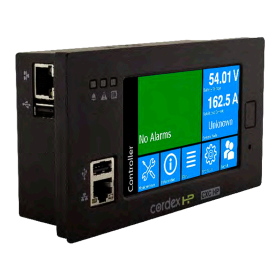
Cordex® CXC HP Controller Software Manual | 3 - Introduction • USB: Dual ports on both the front and rear of the controller for upgrades or file management via a standard USB drive. • CAN: Dual independent CAN bus ports for communication with the Cordex® and AMPS family of products. • Real-time clock with field replaceable lithium battery: Allows timestamps on alarms and events. • System fail alarm/relay: Activates when there is a major internal failure. During such a condition the unit attempts to reset. Figure 3-1 Cordex® CXC HP controller (2RU model) Status LEDs LCD screen Ethernet (back) USB (back) Home Reset USB (front) Ethernet (front) 3.2.1. -
Page 34: Watchdog Alarm
Cordex® CXC HP Controller Software Manual | 3 - Introduction • Four current sensors • 12 Form C relay outputs See the Reference section for a full list of power and ADIO modules that are supported by the controller. 3.2.2. Watchdog alarm The System Fail Relay activates (de-energized) when there is a major internal failure if the controller is not running properly. The unit would attempt to reset. The relay is energized when the controller software starts up. The relay remains energized during normal operation. If the controller loses power, or reboots, the relay is de-energized, which can be used to indicate an alarm condition. When the hardware watchdog timer is not updated by the controller software for more than 30 seconds, the controller is determined to be not running normally. After 30 seconds, the relay will be de-energized, and the unit would reset. 3.2.3. Typical system configuration The controller is a scalable software platform that allows multiple systems to be created and managed by one controller. The user interface is organized around system inventory so you only see the systems that you have created and you can manage them independently. Both the web interface and the LCD provide a summary of all systems monitored by the controller as well as controller and alarm information. The figure below shows a specific DC power system with the following elements: 0350058-J0 Rev AL Page 33... -
Page 35: How To Get Help
Cordex® CXC HP Controller Software Manual | 3 - Introduction • Cordex® CXC HP controller and ADIO modules with CAN bus connections • One or more rectifiers • A battery string • A shunt to measure battery current • A battery low voltage disconnect (LVD) in series with the battery string Figure 3-2 Typical DC system configuration Rectifiers AC Source (Energy Conversion) DC Load DC Bus Ethernet CAN Bus Battery LVD CXC HP Battery Shunt ADIO Battery (Energy Storage) 3.2.4. How to get help The controller has Help on the web interface and the LCD dashboard, but not on the in-shelf display ... -
Page 36: Figure 3-4 Accessing Help On The Web Interface
Cordex® CXC HP Controller Software Manual | 3 - Introduction Accessing Help on the web interface: Select any of the items on the dashboard area and the Help field displays. The help menus provide a description of the item, and in most cases a default value for the field. Figure 3-4 Accessing Help on the web interface The software manual can uploaded to the controller for quick access. Follow the steps in the Uploading the Software Manual section. Once uploaded, access the manual via the web interface by selecting Accounts icon on the right of the top bar, which looks like a small person. Figure 3-5 Accounts and shortcuts 0350058-J0 Rev AL Page 35... -
Page 37: Getting Started
4. Getting started This section explains how to navigate the menus and basic connection, monitoring, and control functions using the LCD, the in-shelf display, and the web interface of the controller. 4.1. Apply power The controller and most ADIO modules are designed to run on battery or DC bus power for 12, 24, and 48 volt systems. A redundant input power module (PN: 0180045-001) is available to simplify the connection of power from above and below a battery LVD to both the controller and ADIO modules. 1. Apply power to the controller (for example, close battery breaker or rectifier input and output breakers). 2. The LEDs start cycling, and then after a few seconds the Cordex® CXC HP logo displays. 3. Wait for approximately about 30 seconds. The LEDs will turn off and the controller software will load. 4. Once the software is loaded, the green LED turns on (it may turn to yellow or red depending on the controller alarm state). The front panel display shows the dashboard. 4.2. Connect to the controller There are three options for connecting to the controller web server from a web browser running on your computer: • Through a local area network (LAN) • Direct connection with IP auto-configuration • Direct connection with static IP address Notice: If the Require Login for Sensitive Information setting is enabled, a login will be required to view the IP settings on the LCD. - Page 38 Cordex® CXC HP Controller Software Manual | 4 - Getting started Connection through a LAN 1. Use the LCD to verify that the Ethernet port is configured to acquire an IP address automatically. IP Address Mode can be found in the Configuration table at: Shortcuts > Ethernet > Ethernet/ Rear. Notice: Enable DHCP at Controller > Communication > Ethernet. Go to the desired ethernet port and select the Change Network Configuration Wizard button in the Configuration table.
-
Page 39: In-Shelf Controller
Cordex® CXC HP Controller Software Manual | 4 - Getting started 1. Connect an Ethernet cable to the front or rear port of the controller and your computer. Your computer must also be configured to allow IPv6 addresses to be used. 2. Use the LCD to determine the IPv6 address that has been automatically configured. The IP address should use the colon-hexadecimal format: fe80::wwww:xxxx:yyyy:zzzz 3. Enter this IPv6 address into the address bar of your web browser and select enter. The web Login screen displays. Direct connection with default static IPv4 address Contact your IT department if you are unsure of how to do this. 1. Connect an Ethernet cable to the front port of the controller and to your computer. Your computer must be configured with a static IP address (for example, 10.10.10.202) and subnet (for example, 255.255.255.0). 2. Use the LCD to verify that the IP address for the front port is similar to your computer’s IP address (for example, 10.10.10.201). 3. Enter the controller’s IP address (for example, http://10.10.10.201) into the address bar of your web browser and select enter. The Login webpage displays. 4.2.1. In-shelf controller Some systems may have an in-shelf controller display. They do not require a login. The display enables you to execute a set of commands much like the LCD on the 2RU controller. From the dashboard, use the Select button to enter a menu. When you enter a menu, the top item is highlighted. To go to another menu scroll through using the Forward and Back buttons. To execute a highlighted menu item, select the Select button. -
Page 40: Controller Menu
Cordex® CXC HP Controller Software Manual | 4 - Getting started a. Enter the default user name: admin (or the user name supplied by your administrator). b. Enter the default password: admin (or the password supplied by your administrator). Notice: Once logged in, the session expires after 3 hours, or after 60 minutes with no activity. Log into the LCD: 3. From the main dashboard of the LCD, select Login. a. Enter the default user name: admin. b. Enter the default password: admin. 4. Select the check mark to complete the login process. The main dashboard displays. 4.3.2. Controller menu The top level controller menu bar contains eight items: Dashboard, Power Flow, Controller, Systems, Modules, Alarms, Logs, and Shelf Layout. Similar menu items are available under the "Menu" button ... -
Page 41: Overview Of The Lcd
Cordex® CXC HP Controller Software Manual | 4 - Getting started Figure 4-1 Menu structure 4.3.3. Overview of the LCD The LCD is a touch-sensitive color panel on the front of the controller. The display is always on when the controller is first powered up but after 20 minutes of inactivity the user will be logged out and the display will be turned off. Touching the home button or the LCD in any spot reactivates the LCD screen. It is possible to change the inactivity time-out of the LCD in the Controller > Settings > User Interface menu, in the LCD Preferences table. The time-out can be set to 20 minutes, 1 hour, 4 hours, or 8 hours. However, to prevent the LCD from wearing out, it is strongly recommended to leave this setting at 20 minutes, unless temporarily changing it for commissioning or demonstrations purposes. The LCD is most responsive to touch when firm, substantial pressure is applied. The LCD does not usually respond to light, quick taps. A stylus may be used if desired. The default screen that displays on the controller when it is powered up and running normally, is called the dashboard. See the following figure. Page 40 0350058-J0 Rev AL... -
Page 42: Figure 4-2 Controller Lcd Dashboard
Cordex® CXC HP Controller Software Manual | 4 - Getting started Figure 4-2 Controller LCD dashboard Active Alarms System Status color coded battery voltage alarms based load current on severity system mode Maintenance Menu Login Information Shortcuts access to access to access all access to alarm cutoff serial number controller most often Logout settings... - Page 43 Cordex® CXC HP Controller Software Manual | 4 - Getting started For support of controllers that manage multiple power systems, there is a configuration option which allows the dashboard to shrink the alarm tile to show an extra System Status tile. Below the Alarm and System Status data tiles there are five buttons providing access to the rest of the controller’s functionality. Maintenance: Provides easy access to frequently-needed maintenance tasks including the Alarm Cut- Off. Pressing the Maintenance button takes you to the Maintenance screen. The first page contains general shortcuts, like Alarm Cut-Off, Forget All in Comms Lost and Replace ADIO. Each system defined is also listed on the main page. Pressing a system button provides access to a page of system- related maintenance shortcuts. Figure 4-3 Maintenance page Figure 4-4 System maintenance page Information: Provides contact information for technical support, as well as general information about the controller such as the serial number, software version, and Operating System version. Menu: Provides access to the controller menu, which follows almost the same menu structure as the web interface, with some exceptions. Some examples of menus not available on the LCD are: • Power Flow • Shelf Layout Shortcuts: Provides quick access to several key functions that are used often, such as the Ethernet settings. The Shortcuts menu also provides access to functions only supported via the LCD such as: Page 42...
-
Page 44: Figure 4-5 Lcd Menus Page
Cordex® CXC HP Controller Software Manual | 4 - Getting started • USB file browser • Backup • Restore • Display Calibration 4.3.3.1. LCD menu button This section provides an overview of all the LCD menus on the controller. The LCD has a menu structure that mirrors the web interface. Select the Menu button on the LCD dashboard to navigate and select menu items. The menu items are as follows: • Controller • System • Modules • Alarms • Logs When a menu item is selected, it is highlighted in blue, and an arrow displays on the right side of the screen. Select the arrow to navigate to the next page. Figure 4-5 LCD menus page For example, select Menu > Controller > About > General to view detailed information about the controller. -
Page 45: Figure 4-6 Controller Status Page
Cordex® CXC HP Controller Software Manual | 4 - Getting started Figure 4-6 Controller status page When selected, some views display a pencil or hand icon on the right side of the screen which means you can edit settings or perform actions. For example, from the Controller > Settings > Time and Date screen select the pencil icon to set the following: • Current Time and Date • Time Zone • Daylight Saving Time Method • Network Time Server Address Figure 4-7 Time and date page To edit the time zone, you can choose from the list of supported time zones. Page 44 0350058-J0 Rev AL... -
Page 46: Figure 4-8 Time Zone Page
Cordex® CXC HP Controller Software Manual | 4 - Getting started Figure 4-8 Time zone page If Network Time Server Address is selected, a text field, and on screen keyboard displays. Figure 4-9 Network time server page Selecting the back arrow cancels an edit, selecting the checkmark accepts the changes. Selecting the Help icon displays a help screen with more information about the item. If the edit is unsuccessful an error displays in red text below the text box. You can either try again, or select the back arrow to abandon the change. Another screen that displays when selecting items, is the Execute screen. For example, Synchronize Time. Most edits and executable actions (except ALCO and Restart) require you to login. If you select an editable item or executable action before logging in, the controller responds providing an opportunity to log in and then continue with the action. When you select the back arrow the action is canceled. If you select Execute, the command is executed, and the controller provides feedback on whether the action was successful. 0350058-J0 Rev AL Page 45... -
Page 47: Figure 4-10 Synchronize Time
Cordex® CXC HP Controller Software Manual | 4 - Getting started Figure 4-10 Synchronize time 4.3.3.2. LCD shortcuts button The LCD Shortcuts menus provide quick access to often-used areas of the controller menu, as well as additional functionality not available via the standard menus. Figure 4-11 Shortcuts Functions available through the Shortcuts menu are as follows: Ethernet: Provides access to the Controller > Communication > Ethernet page, and displays information for each Ethernet port. Viewing and editing the Ethernet configuration is one of the most often-used features from the LCD. Selecting an Ethernet port from the list allows you to view and edit the detailed information for that port. Figure 4-12 Ethernet page Page 46 0350058-J0 Rev AL... -
Page 48: Figure 4-13 Inventory Summary Page
Cordex® CXC HP Controller Software Manual | 4 - Getting started Inventory summary: Provides access to a special Inventory Summary page, which allows for a quick check of what devices are available. The top-level inventory page shows counts of each device type. Selecting the icon associated with that device displays a list of that type of device. Selecting an individual device from the list displays that particular device’s details. Figure 4-13 Inventory summary page Dashboard config: Provides a shortcut to the LCD Preferences page which provides the opportunity to switch the dashboard configuration between Automatic and Manual and also to change the LCD default between a single-panel view, dual-panel view, or a wide-data panel display. The dual-panel view has a single top alarm, and provides two system status data panels, which allows data points for two different systems (for example, DC and Converter) to be shown in the case of a multi-system configuration. The wide data panel view allows you to display six signals from a single system. In Automatic mode, the dashboard shows a single panel view if there is one system, and a dual panel view if there are two systems. In Manual mode a user can select the option to have the LCD main dashboard display only a single system, even if there are two installed. Figure 4-14 Dashboard with multi-system panels 0350058-J0 Rev AL Page 47... -
Page 49: Figure 4-15 Dashboard Using Wide Data Panel View
Cordex® CXC HP Controller Software Manual | 4 - Getting started Figure 4-15 Dashboard using wide data panel view To access the wide data layout, go to Controller > Shortcuts > Dashboard Config > LCD Dashboard Option > Wide Data Panel. If there is more than one system on the controller. Switching to Wide Data Panel from Automatic is a two-step process. Once Wide Data Panel is chosen, a specific system must be selected so that the data values display for that specific system. Language: Provides access to the Controller > Settings > User Interface > LCD Preferences > LCD Language setting, where the language for the LCD can be changed to any of the available translations. ... -
Page 50: Overview Of The Web Interface
Cordex® CXC HP Controller Software Manual | 4 - Getting started Backup: Selecting this button, allows you to do a back-up of the system. It backs up the application, as well as the config file. These backups are saved on a USB drive. Notice: For the backup to work properly, only one USB drive should be attached at backup time. If a file named Cordex HP.Backup already exists in the root directory of the USB drive, it is overwritten with the current backup. -
Page 51: Figure 4-18 Dashboard Overview On Web Interface
Cordex® CXC HP Controller Software Manual | 4 - Getting started • Red for major or critical alarms • Amber for minor alarms • Blue for warnings Selecting the Alarm tile takes you directly to the Active Alarms menu. If there are no active alarms, a No Alarms message will be shown. In some situations, the controller will provide hints as to certain behaviors of systems, or mis-configurations. If there are no alarms, one hint may be displayed below the No Alarms message. Hints are explained in more detail in later sections. The upper-right tile displays System Status Bar(s) which contains summary information for the systems. Selecting the system link at the top of the System Status Bar(s) takes you directly to the System status screen. The upper right-side of the of the web interface also provides the Shortcuts and Language dropdown menus. The small cog icon is the Shortcuts menu which provides a quick link to the user manual, account settings, and a few other often-used items. From the Language dropdown menu you can change the language from English to other languages as well as choose imperial or metric measurement units for the display. Figure 4-18 Dashboard overview on web interface Shortcuts Alarm Notifications Language... -
Page 52: Figure 4-19 Global Search Example
Cordex® CXC HP Controller Software Manual | 4 - Getting started As you enter the menus, the interface provides a context sensitive breadcrumb trail at all levels so that you can “see” where you are within the system and go back to any previous menu. The lower area of the main dashboard contains system tables with detailed information about: • Controller Status • Systems • Active Alarms You can work with the system directly from this area. 4.3.4.1. Global search Within the web interface, there is a search bar at the top-right of the screen. This search bar allows you to quickly find the following information: • Configuration • Alarms • Buttons To search, enter terms into the search box. After the search returns a result, you can select Go To View to go to the view the status of that Configuration, Alarm, or Button. For Configuration, you can select the EDIT button to directly edit this value. The following example illustrates the usage of the search bar to find the Output Voltage Low alarm for a DC System. Figure 4-19 Global search example 4.3.4.2. Paging, sorting, and filtering Within the web interface there are three additional features that help you find information: paging, sorting ... -
Page 53: Figure 4-20 Web Interface Table Features
Cordex® CXC HP Controller Software Manual | 4 - Getting started Paging: Displays multiple page tabs on tables that have a large quantity of information. If there is too much information for one table the table’s lower edge contains a list of numbers which allows you to scroll through the information. Sorting: Provides a way to sort the table columns, either ascending or descending similar to any standard spreadsheet program. Filtering: Provides an easy way to refine the information shown in a particular table. The search bar on the upper-left side performs a search on each of the space-separated terms in all columns of the table. The “Aa” toggle can be used to make the search case-sensitive, and the “abc” toggle can be used to only match whole words. For example, typing “dc system major” will display all alarms of priority Major on the DC System. The following example shows these features on the All Alarms table. Figure 4-20 Web interface table features 4.3.4.3. Controller menu This section provides an overview of the Controller menu. The controller area has a total of six sub- menus: Status, Settings, Communication, Files & Upgrade, User & Security, and Programmability. About: Provides access to sub-menus providing various status information about the controller, including: Page 52 0350058-J0 Rev AL... - Page 54 Cordex® CXC HP Controller Software Manual | 4 - Getting started • General: General information and active user sessions. The General table includes a button to reset the controller or export diagnostic information. • Storage & Memory: Flash refresh, flash disk, application storage, memory, and alarms tables. • Factory Information: Factory information and branding tables. Settings: Provides access to configuration sub-menus including the following: • Site Information: Description and location tables. • Time & Date: Time and date table for all related settings. You can also synchronize time and data to a network time server or to a web browser with the buttons. • Speaker (if available): View the speaker state, enable or disable it, and edit the external speaker relay. • User Interface: User interface, LCD preferences, in-shelf controller display preferences, file preferences, web interface preferences, custom views, and system dashboard values. • Maintenance Mode: See status, alarms, and relay behavior during maintenance. You can also manually start and stop maintenance mode on this page. Communication Provides sub-menus for the many different communication protocols the Controller supports, including: • Ethernet: Configure Ethernet, ports, and VLAN support. •...
- Page 55 Cordex® CXC HP Controller Software Manual | 4 - Getting started • Configuration & Software Backup: Import and export configuration files including clones. Create configuration restore points, export a controller backup, and view restore point information. • Software Upgrade: Upload new controller software (application) and OS (operating system) to upgrade or download the controller. • Licenses: Import and export the license key file, enable and disable temporary licenses, and view related alarms. • Software Manual: Upload the HTML software manual to the controller. Users & Security: This menu provides access to user configuration and other settings related to authentication and permissions, such as: • Users: Configure users, view active user sessions, and machine account status. • Remote Authentication: Configure RADIUS and TACACS+ settings. • Remote Configuration Lockout: View and configure remote configuration lockout including status and related alarms. Programmability: The controller provides some features to allow users to customize its behaviour, for example, custom alarms, a calculation engine, and a scheduler: • User Alarms: Add digital user alarms and threshold user alarms. •...
-
Page 56: Figure 4-21 Alarms Menu
Cordex® CXC HP Controller Software Manual | 4 - Getting started 4.3.4.5. Modules menu This section provides an overview of the Modules menu. The Modules menu has the following tables: CAN Modules, Power-Line Comms Modules, Firmware Upgrade, and Firmware Files. CAN Modules: Provides a table to view or locate all modules. Power-Line Comms Modules: To view all PLC modules in this table, their parent CAN module must be part of a system. Firmware upgrade: Provides a table to start and monitor a firmware upgrade. Firmware files: Provides a table to view, upload, or delete firmware files. Notice: Even if a system is configured to auto-assign devices, once a rectifier has been unassigned from the system, it must be manually reassigned back into the system. -
Page 57: Figure 4-22 Logs Menu
Cordex® CXC HP Controller Software Manual | 4 - Getting started 4.3.4.7. Logs menu The logs section has several log-related sub menus : Events & Alerts, Battery, Power Outage, Datalogs, and Performance. Every log can be exported to CSV files for further analysis. Figure 4-22 Logs menu Events & Alerts: The Events table provides a list of system and controller events that record configuration changes, alarms and general controller and system operation. The Module Alerts table shows the module alert name and module serial number when a module reports an alert condition. Battery: The battery log records the duration and change in capacity (Ah) for every charge and discharge of a battery. If you have Battery Runtime & Heath enabled, the log will also record the change in State of Charge (SOC) and State of Health (SOH). Power Outage: The power outage log records the start time, end time and duration of each power outage. Datalogs: The datalog allows users to record measurements at set intervals over a period of time using the controller sensors and calculated values as inputs. Performance: The performance log provides daily roll-ups with a minimum, maximum and average value for key usage statistics. For power systems, that usually includes the input voltage and current and the ... -
Page 58: Figure 4-23 Shelf Layout Menu
Cordex® CXC HP Controller Software Manual | 4 - Getting started Figure 4-23 Shelf layout menu From the Shelf Layout you can select any of the devices to be taken to the device details page. The following modules support the Shelf Layout function: • Cordex® HP 12 kW 48 Vdc rectifier system • Cordex® HP LPS36 line power system • Cordex® HP eLimiter+ distribution system • Alpha® Inverter Module (AIM) 2500 If all the devices in a system do not have bay ID, shelf ID, and slot ID information then the view will switch to a simple table with each device on a separate row. Refer to your device manual to determine whether your devices support this feature. 4.3.4.8.1. Configure shelf layout manually If devices do not provide bay ID, shelf ID, slot ID information then the Configure Shelf Layout feature can be used to manually configure a layout. On the Shelf Layout page, a Configure Shelf Layout link is provided for DC systems and converter systems. If all the modules of your system have bay ID, shelf ID, and slot ID information, the button will appear on top of the system’s shelf layout. Otherwise the button will appear on the simple table of modules. To map your modules to the Shelf Layout: 1. -
Page 59: Overview Of The In-Shelf Display
Cordex® CXC HP Controller Software Manual | 4 - Getting started 5. To remove a module from the layout grid, select the red “X” icon. The module will return to the list of available modules. 6. Repeat the steps above until you have mapped all your modules. 7. After you have mapped all the modules, go to Shelf Layout on the main menu and you will see the completed shelf layout grid. If you select a module in the layout, you will be taken to the details of the module. In the details page, you will see that the bay ID, shelf ID, and slot ID information is set to where you dropped the module. 4.3.5. Overview of the in-shelf display In-shelf controllers have a small OLED display. This displays shows 30 characters total (six characters wide, five lines high) and the controller has three navigation buttons and one reset button. In-shelf display screens The in-shelf display has three main operating modes: dashboard, menu, and screen saver. After 20 minutes with no activity, the in-shelf controller goes into screen saver mode and the display shuts off. From screen saver mode, press any of the three navigation buttons to re-activate the screen and enter dashboard mode. In dashboard mode, the in-shelf display shows the key operating parameters of a system. For example, output voltage and load current. If more than one system is defined, you can cycle between systems using the Forward and Back buttons. With multiple systems, you can specify a default system, which is then displayed first. To set a default system, from the web interface, go to the Controller > Settings > User Interface and select a system from the In-Shelf Controller Display Preferences table. -
Page 60: Email Notification
Cordex® CXC HP Controller Software Manual | 4 - Getting started When you enter a menu, the top item is highlighted. To go to another menu scroll through using the Forward and Back buttons. To execute a highlighted menu item, select the Select button. To exit a menu and return to the main OLED display dashboard, scroll to the Back command, and then select the Select button. The following figure shows an example of the menu screen. The following table provides a full list of menus available via the in-shelf display. Table 4-1 In-shelf controller full menu Menu label Description ALCO Perform the alarm cut-off command. Rstrt Perform a restart of the controller. IPv4 Display the IPv4 address, subnet, and gateway for this controller. IPv6 Display the IPv6 addresses assigned to this controller. AutoIP Set the IP to Automatic (obtained from DHCP server). RstIP Reset the IP to Static Default (IP: 10.10.10.201, subnet: 255.255.255.0). Port Displays the port number for the controller. Backup Backup the controller application and configuration to a file on a USB device. Resto Restore the controller application and configuration from a file on a USB device. Upgra... Upgrade the controller application from a file on a USB device. OS Upg Upgrade the controller’s operating system from a file on a USB device. -
Page 61: Figure 4-24 Smtp Client And Server Default Ports
Cordex® CXC HP Controller Software Manual | 4 - Getting started For email notifications in a different language, go to Controller > Settings > User Interface and set the LCD Language in the LCD Preferences table to a preferred language. Although this setting is called LCD Language, it serves as the default language for the controller, and will affect the language of email notifications. Figure 4-24 SMTP client and server default ports A summary of alarm activities in the controller can be delivered using email. A period of monitoring time is configured, and then all alarms within that period are reported. This summary is designed to assist decision making when determining the urgency of any action required to resolve issues that may occur in your system. Table 4-2 Email notification features Feature Description HTML Based Emails HTML based emails provide better formatting features such as color cod ing and table alignment. Multi-level Security Different security levels are available and automatic detection is executed to support the appropriate level. Direct SSL connection (default port 486) is not currently supported. Encrypted SMTP Server Password The password used for authentication on the SMTP server is securely en crypted. Test Email Capability A test button is available to send a test email ensuring proper configura... - Page 62 Cordex® CXC HP Controller Software Manual | 4 - Getting started Email content • Subject line with filterable text and alarm counts. • Static title for filtering. • Configurable name of the controller. • Configurable location of the controller which provides a link to open Google Maps showing the location of the controller (Internet connection required). • Time and date of the notification. • List of up to ten active alarms sorted by priority with an active alarm count indicator showing total active alarms. • List of up to ten cleared alarms sorted by priority with a cleared alarm count indicator showing total cleared alarms. How email notification works • An alarm activity is the main item that will trigger an email notification. To avoid overwhelming the network, emails are only sent out at the configured interval set in the Email Destination table. • When alarm transitions occur (for example, alarms activating or clearing) a timer starts from the first transition. During this collection period, all alarm transitions are collected for reporting in the email that is sent out at the end of the period. Continued transitions after the email is sent will start another timer for the next email notification. • Active alarms are reported as a snap shot of all currently active alarms, regardless of when they activated or if they were a part of a previous notification. • All cleared alarms are collected based on the last occurrence within the collection period. This is to avoid multiple entries of the same alarm in the case the alarm toggled multiple times.
-
Page 63: Setup Snmp Communication
Cordex® CXC HP Controller Software Manual | 4 - Getting started Table 4-3 Email configuration Configuration Description Enable Email notification defaults to inactive. Enabling allows email notifications to go out when all configuration information is set correctly. SMTP Server Address A DNS name or an IPv4 or IPv6 address will work in providing a target lo cation of the email server. Port Default port is 587 Domain This is a DNS formatted string (words separated by '.') used for identifying the client to the SMTP server. Required for most public SMTP servers like Google. SMTP User Name The username used for authentication to the server to access SMTP re sources. SMTP Password The password used for authentication to the server to access SMTP re sources. Set this value by using the Set SMTP Server Password button. You can clear the configured password by using the Clear Server Pass word button. From The From field is used as the source of the email and is usually the same as the Username provided to authenticate the client to the SMTP server. For example, Gmail requires this value to be the email address of the ac count in use. The To field is for the destination or receiver of the email notification. This ... -
Page 64: Setting Up Modbus Communication
Cordex® CXC HP Controller Software Manual | 4 - Getting started There are two main steps required to add a new agent to your SNMP system: • Configure the agent with the IP address of your SNMP manager (tell the agent to send information to the manager). • Compile the agent's Management Information Bases (MIBs) into the manager (tell the manager how to interpret information sent by the agent). Configure an IP address to receive notifications Configuring an IP address for notifications is referred to as Subscribing to Notification Services. Up to ten IP addresses can be configured. SNMP monitoring systems need to compile and install the ALPHA- NOTIFICATION-MIB. Please refer to the user guide of the SNMP manager for this process. For each of the ten SNMP notifications addresses, the user can select the address and select the GO TO button to see more details about that particular monitoring destination, and to edit details. Notice: For detailed information on using SNMP, see the SNMP Integrator Guide (User Guide ID: 0350099-J0) on the Alpha®... -
Page 65: Setup Syslog Communication
Cordex® CXC HP Controller Software Manual | 4 - Getting started Notice: For detailed information on using Modbus, download the Modbus Integrator Guide (User Guide ID: 0350114-J0) on the Alpha® website, www.alpha.ca. 4.7. Setup syslog communication Syslog overview Syslog (System Logging Protocol) is a communication protocol which is used to send system log or event messages to a server that supports Syslog. This protocol is a Simplex Communication Protocol meaning information only gets sent in one direction. The controller, acting as an agent, has the capability to send event log and module log messages to a configured Syslog server. 4.7.1. Syslog agent configuration To setup the Syslog Agent on the controller: 1. -
Page 66: Table 4-4 Controller Alarm Priorities To Syslog Severities Mapping Table
Cordex® CXC HP Controller Software Manual | 4 - Getting started Notice: The message presented is not the entire message displayed and the timestamp is formatted via rSyslog on Linux. It is to be used as a reference for the information detailed below. Using the Syslog message format, the controller will curate a message with the following: 1. In Syslog message format, the AppName is the CXCHP[Version]. 2. In Syslog message format, the MsgId are the specific types of events generated by the controller. These events categories are: ConfigurationEvent, ControllerEvent, AlarmEvent, and ModuleEvent. ... -
Page 67: Dc Power Systems
5. DC power systems This section provides a brief overview of the components and functions within a typical DC power system. A basic power system usually consists of rectifiers and batteries, but can also include other components. 5.1. Guidelines for commissioning the DC system The following section contains basic guidelines for commissioning a DC power system. Overall system commissioning consists of four parts: power system inspection, battery inspection, commissioning the system, and testing the system. Commissioning should only be conducted by a qualified technician. For more detailed information refer to the relevant system manual for your specific system. Perform an inspection of the power system to confirm that the mechanical and electrical requirements and parameters are within specification. Pay special attention to the battery to ensure it is installed safely and correctly, and that the battery terminals are torqued to specification. 1. Make sure all power to the system is off. Are all batteries disconnected, rectifier modules are removed, fuses pulled and circuit breakers turned off? 2. Make sure the battery polarity is correct. Use a voltmeter if necessary to confirm. 3. Install one rectifier. 4. Turn on the AC to the rectifier and allow it to start up. Verify that the system starts up, and the controller turns on. Did the rectifier turn on? AC and DC lights on? Notice: With no load and batteries disconnected, the rectifier may have a fail alert. This should go away when load is connected. -
Page 68: The Battery Mode
Cordex® CXC HP Controller Software Manual | 5 - DC power systems • Battery disconnect operation • Alarm test 5.1.1. The battery mode The Battery Mode value, as shown in top section of the web interface or in the system Status page, indicates the state of the battery in the system. In a system with a fully charged battery, the Battery Mode will be Float which indicates the battery is floating. In a system that is charging, the Battery Mode will be Charging. The adjacent value either show Bulk (battery is charging at constant current) or Absorption (battery is in the absorption phase of charging). In a system that is discharging the Battery Mode will either be Discharging (AC mains has failed) or Test Discharging (battery test in progress). The Battery Mode may also be No Battery (no battery in the system), Disconnected (battery appears disconnected) or Unknown. When it is Unknown then the controller is busy trying to determine the state of the battery. If this value persists for more then a minute or so, it may indicate that one or more of the ... - Page 69 Cordex® CXC HP Controller Software Manual | 5 - DC power systems Modules A module is a device that communicates information. Most modules in a controller system will be CAN devices such as rectifiers, converters, inverters, and ADIO modules. Future releases, may have modules such as Ethernet and USB-serial connected modules. Since the controller can communicate with modules, each module in the system should also have a Communications Lost alarm. Most modules are replaceable, because of this there are functions within the system to remove old modules and create new ones. Some modules also have the ability to download reports and diagnostic information via the controller. Inventory An inventory item is an item that is directly involved in the flow of power through the system. For example, a rectifier is an inventory item but a controller or an ADIO module is not. Other examples of system inventory are: AC source, rectifier, load, battery, disconnect, shunt, DCCT, breaker, and power meter. Setting up the inventory of a system focuses on the monitoring, not the control of the system. You can set monitoring in one of three ways: 1. If the inventory item is also a module, you can communicate with it directly, such as with rectifiers. 2. If the inventory can be measured or controlled via an ADIO module, then you can map the inventory to read data through the ADIO module, such as with shunts, batteries, current transducers, and disconnects. 3. If the inventory item’s values can be inferred through a calculation, then you can map the inventory to use that calculation such as with AC sources and DC loads. System functions System functions are the major features of the system. Some examples are: • Battery charging • Battery runtime estimation • Charge current control • Voltage regulation • Temperature compensation Once the inventory is in place to monitor the system, you can configure and test the system functions to ...
-
Page 70: Mixed Rectifier System
Cordex® CXC HP Controller Software Manual | 5 - DC power systems 5.2.2. Mixed rectifier system You can add any rectifier to the DC system that has the appropriate DC bus voltage. Some of the System Functions assume that the controlled rectifiers and managed batteries are the only source of power on the DC bus. Those System Functions work best with either a single rectifier model or models that have been designed to work together such as, the Cordex® 1.8 kW and the Cordex® HP 2.0 kW rectifiers, or the Cordex® 3.6 kW and the Cordex® HP 4.0 kW rectifiers. Mixing of other rectifier types is not recommended. If you need to mix other sizes and types of rectifiers you many need to turn off some of the System Functions for the DC System. See your system manual or contact Technical Support if you encounter this situation and do not have instructions on how to set up the System Functions. 5.2.3. Battery charging The controller applies a typical three-stage charging cycle including Bulk Charging, Absorption Charging, and Conditioning which is sometimes called float charging. Figure 5-1 Three-stage charging cycle Bulk charging After the bulk charging stage, the battery should be in a 70 to 90 percent state of charge. On the Systems > DC System > System Functions > Charging page, in the Primary Charge Current Control table, you can enable and disable charge current control and set the charge current limit (C/X) in hours. -
Page 71: Battery Temperature Compensation
Cordex® CXC HP Controller Software Manual | 5 - DC power systems Absorption charging After the absorption charging stage, the battery should be in a 95 to 98 percent state of charge. On the Systems > DC System > System Functions > Charging page, on the Elevated Absorption Charging Status table, you have the option to charge the battery at a voltage higher than the float voltage. The higher voltage is used to speed up the absorption charging stage after a prolonged AC power failure. Conditioning - float The conditioning or float charging stage brings the batteries to 100 percent state of charge and maintains it there. When the system is in the conditioning stage it is usually at the Float Voltage. When the system is in conditioning-float, a higher Equalize Voltage or Boost Voltage can be applied from the Systems > DC System > System Functions > Equalize & Boost menu. Conditioning - equalization When a string of battery cells or blocks are charged, a single charge current is applied on the group. ... -
Page 72: Battery Runtime And Health Estimation
Cordex® CXC HP Controller Software Manual | 5 - DC power systems Figure 5-2 Temperature compensation voltage graph Temperature Compensation Battery Voltage Curve Lower Temperature Breakpoint Upper Temperature Breakpoint Temperature (°C) Battery performance and life expectancy are directly related to the battery ambient temperature. The optimum operating temperature for battery operation is typically 25℃ (77℉). Above this temperature battery life may be reduced and below this temperature battery performance may be reduced. Thermal runaway occurs if the internal temperature rises due to overcharge, high ambient temperature or internal fault. Temp Comp automatically adjusts the float voltage as the battery temperature changes to protect the battery from thermal runaway. The Temp Comp function adjusts the system voltage every two seconds, as the temperature changes, and provides for a maximum voltage change of 0.2 V over this interval. Temp Comp occurs at standard rates commonly referred to as slope-compensation settings. The slope of the Temp Comp curve in either mV/°F/Cell or mV/°C/Cell can be set via the Systems > DC System > System Functions > Temperature Compensation menu in the Configuration table. The value is set based on the battery manufacturer’s information. Since a battery can have multiple temperature sensors, temperature compensation uses the average of the temperature readings to determine the battery temperature on which to adjust the battery voltage. The average is used as long as all the temperature readings are within 5℃ (9℉) of each other. When a temperature reading rises, perhaps due to local heating or thermal runaway, and reaches a point ... -
Page 73: Low Voltage Disconnect Operation
Cordex® CXC HP Controller Software Manual | 5 - DC power systems Estimated State of Charge (SOC), and an Estimated Battery Runtime (RTR) remaining at all times. It is not always practical to estimate these values. For example, if the system goes into a charging stage immediately after a restart, there is no way to estimate the SOC or RTR. The accuracy of the estimated battery health improves as the battery undergoes more discharge cycles and it also improves with deeper discharges. If a battery discharge occurs that goes below an SOC value of 80 percent, then the Battery Runtime & Health Estimation function creates a Last Battery Discharge Summary, a Last Battery Recharge Summary and recalculates the Estimated Battery Health. If estimated battery health is less than 80 percent then that battery is normally due to be replaced. 5.2.6. Low voltage disconnect operation Whenever the system parameters requires the LVD to be activated, a 60 second countdown and audible warning begins. When the countdown reaches zero, the LVD is activated. During the countdown, a command in the disconnect menu can be pressed to inhibit LVD activation. When the disconnect first changes to Pending, every user logged into the system will receive notification that the disconnect is about to activate, and the option to inhibit it. To release the inhibit, you must activate ... - Page 74 Cordex® CXC HP Controller Software Manual | 5 - DC power systems • The voltage must be greater than the connect threshold or • One or more optional reconnect conditions are true and • All optional disconnect conditions must be unknown or false • If the option to require AC for reconnect is enabled and AC input is not present no reconnect will occur until AC returns or this option is disabled. To better support use as a load shedding disconnect there are three configuration parameters that may be used to further customize the behavior: 1. Allow disconnect during battery test: By default this is set to No but may be set to Yes. Example: using the battery test to observe and measure the runtime available to critical loads after less important loads are disconnected. 2. Require AC info for reconnect: By default this is set to Yes but may be set to No. Example: if there are additional DC sources (like solar panels or a DC generator) on the voltage bus that are capable of supporting the loads even when AC is lost. 3. Required time to stay disconnected: By default this is set to 0 seconds. It may be set to a non- zero number in to ensure that a load is fully powered off before reconnecting. Some loads may not ...
-
Page 75: Battery Test
Cordex® CXC HP Controller Software Manual | 5 - DC power systems Alarm will trigger indicating the position of the contactor is not in its expected state. If this source is not set, the controller will not attempt to close or open the contactor as the state is unknown. Contactor retry countdown The Contactor Retry Countdown is found in the Status table. The contactor retry countdown will automatically start counting down after three retries. After the retry countdown reaches 0, the controller will automatically attempt to retry closing or opening the contactor three times. If the expected state is not reached, the contactor retry countdown will start over. Test disconnect open button To test the contactor, there is a Test Disconnect Open button located in the Status table. A test can only be initiated if the disconnect State, found in the Status table, is Inactive (contactor closed). The Test Disconnect Open button will open the contactor. The contactor will remain open for 60 seconds, then close automatically. 5.2.7. Battery test A battery test is used to update the Estimated Battery Health of a lead acid battery. The settings for this feature can be found in the Systems >... - Page 76 Cordex® CXC HP Controller Software Manual | 5 - DC power systems Test discharge initiation When the test begins, an entry is made in the event log. If the Battery Test Alarm has been enabled, it provides a warning to indicate that a battery test is in progress. The output voltage of the rectifiers is set to the Battery Test Termination Voltage to allow the battery to discharge. Battery Mode changes to Test Discharge when a battery test is started. Test discharge mode runs for the period set as timeout or until the battery test termination voltage is reached or the battery test termination SOC is reached (if enabled). The rectifiers are periodically scanned to ensure that they do not begin sourcing current. If so then the test is stopped and the battery is recharged. The rectifier float voltage is reset to the setting that is stored in the system controller. When the system voltage reaches the end (termination) voltage or a timeout occurs, the system controller will command the rectifiers to turn on and enter FL mode. Activity during test discharge mode Temperature compensation features are suspended during a battery test. When the battery is discharging, the battery test alarm is active. Battery state of health estimation begins at three percent of DOD, but is not displayed unless DOD > 20 percent; the point at which reasonable accuracy can be assured. AC failure during test discharge mode If the AC fails during a battery test, the test is aborted. This places the rectifiers into a state that enables them to resume providing power to the load when AC returns. If the runtime is being displayed, it continues to update. Addition of rectifiers during test discharge mode If rectifiers are added to the system when a battery test is active, they are placed into the same state as ...
-
Page 77: Power Save
Cordex® CXC HP Controller Software Manual | 5 - DC power systems Canceling test discharge mode Test Discharge mode can be canceled by either changing the mode to Float or stopping the test manually. To stop the battery test manually go to Systems > DC System > System Functions > Battery Test and select the Stop Manual Battery Test button in the Status table. Battery discharge test completion Once the battery begins to charge, the recharge cycle begins. Live battery recharge information is available at Systems > DC Systems > System Functions > Battery Runtime & Health menu in the Status table. The test is considered complete once the battery begins to charge. This is due to either, the ... - Page 78 Cordex® CXC HP Controller Software Manual | 5 - DC power systems Configuration table The Configuration table has the following fields: • Power Save: Enable or disable the power save feature on a system. • Module Power for Maximum Efficiency: Provides a percentage at which the module should be loaded to achieve maximum efficiency. Power Save works to get as close to this value as possible. Refer to the module’s installation manual to get information for best performance. If you don’t have this information, use the default value based on the rectifiers used. • Rotate One Module Every: A length of time in days. After the configured number of days, the module that has been in standby longest will be turned on, the module that has been on the longest will be turned off. Module rotation occurs at 3am. Status table The Status table displays which values Power Save calculates. These include the following fields: • Power Save: Provides the general status which may be active, disabled, insufficient redundancy or invalid data suspended. Power Save cannot operate if in a battery test, if AC has failed or if any required data is unknown.
-
Page 79: Create A Dc System Manually
Cordex® CXC HP Controller Software Manual | 5 - DC power systems 80 percent. The remaining 20 percent is considered redundant capacity. This represents rectifier capacity that is immediately available should a rectifier fail. This number can be increased by lowering the Module Power for Maximum Efficiency to cause more rectifiers to turn on – it is up to the user to balance the requirement for redundancy versus operating efficiency. • Estimated Standby Capacity: The estimated amount of capacity for modules that are in standby. Modules table The Modules table displays the Power Save status of all the modules in the system including: serial number, mode, and Hours Supplying Power, In Standby. Hours Supplying Power and Hours In Standby is the time a rectifier spent in those modes. 5.3. Create a DC system manually On a controller, if there is no power system defined, you can create the inventory items needed to monitor and control a DC system. There are four steps to creating a new DC system. -
Page 80: Quick Reference For Configuring A Dc System
Cordex® CXC HP Controller Software Manual | 5 - DC power systems 5.3.1. Quick reference for configuring a DC system The following figure shows the key configuration settings for a DC system that should be set or checked so that the system operates correctly. There are many optional and alarm reporting settings that can also be configured. 0350058-J0 Rev AL Page 79... -
Page 81: Figure 5-4 Quick Reference For Configuring A Dc System
Cordex® CXC HP Controller Software Manual | 5 - DC power systems Figure 5-4 Quick reference for configuring a DC system Page 80 0350058-J0 Rev AL... -
Page 82: Create A Dc System
Cordex® CXC HP Controller Software Manual | 5 - DC power systems 5.3.2. Create a DC system There is no DC power system on a new controller. Creating a DC system is done using the Create System wizard. In the current release, only a single DC system is supported, so if a system already exists on the controller, the option to create a new DC system will not be available. You can also import a configuration file containing a DC system from another controller. A new power system can be created via the Systems > Add or Remove Systems menu from either the LCD or the web interface. Both have wizard assistance to help step you through the process to create the new system. You can create either a 48 V system or a 24 V system. Once the system is created, an associated load, battery, disconnect, and shunt is also created. The DC system will also be created with a reasonable set of defaults and associated alarms. The only value which is mandatory to configure after system creation, is the System Voltage Source, which can be set to any voltage input. It is recommended that this be set to the same input as the Battery Voltage input. All other items, such as Name, Description, System Number, and Serial Number are optional and can be used to describe and organize your system. You can configure the alarms associated with the system. You can enable or disable the alarms, change the priority, map relays to the alarms, and where applicable, modify the thresholds. To create a DC system: 1. Go to Systems > Add or Remove Systems. Select the Create System button to launch the wizard. -
Page 83: Configure Basic Dc System Settings
Cordex® CXC HP Controller Software Manual | 5 - DC power systems 5.3.3. Configure basic DC system settings The Configure System page has three tables (Configuration, System Properties, and Alarms) with some basic settings that must be configured. To configure basic DC system settings (from the main dashboard): 1. Go to Systems > DC System > Configure System. 2. In the Configuration table: a. Set the system name, description, number, and serial number. b. Set the float voltage setting. This is the desired output voltage of the rectifiers when the system is in float mode. c. -
Page 84: Configure The Shunts
Cordex® CXC HP Controller Software Manual | 5 - DC power systems 5.3.5.1. Rectifier configuration guidelines The following are guidelines for setting rectifier configuration. Some or all may apply. Over Voltage Protection Set this value as far above equalize voltage or boost voltage as needed. For a 48 V Threshold system, the usual value is 60 V. The actual upper limit of this setting depends on the rectifier model. If the Rectifier Configuration Error alarm is active, it usually means the OVP threshold is too high or too close to the equalize, boost or float voltage setting. It is necessary to have at least 1 V (for 48 V system) difference between float, equalize and OVP settings. System Start Delay Set this value to delay the start up of all rectifiers when AC returns to give other AC equipment on site a chance to start up first. Module Start Delay Set this value to apply a staggered start delay to individual rectifiers. This helps lim it AC inrush current and gives the controller time to engage charge current control, if enabled, to prevent a battery breaker or fuse from opening. Each rectifier is assigned a module start delay that is a multiple of the configuration value. If the value exceeds 250s, the value starts again at the lowest multiple. For example, if the module start de lay is 60s and there are eight rectifiers in the system, the start delays assigned to the rectifiers will be: 1s, 60s, 120s, 180s, 240s, 1s, 60s, 120s. This means that three recti fiers will be assigned the same 1s, 60s, and 120s delays. Current Limit/Power Limit Set one of these values (not both) to limit the output current of the rectifier. This is nor mally only done if the site has undersized AC breakers or is running on an undersized AC generator. These values must only be set while in float mode. Setting them when the battery is bulk charging may result in too much current to the battery. -
Page 85: Configure The System Loads
Cordex® CXC HP Controller Software Manual | 5 - DC power systems 1. Go to Systems > DC System > Inventory > Shunts. You will see a list of shunts in the system. Add or remove shunts from this page. 2. Select the GO TO button for the shunt you want to configure. 3. In the Configuration table, assign the shunt a name and description. We recommend that you assign the shunt a name that represents the actual shunt. For example you might name it Battery Shunt. 4. Select the Shunt Current Source. This is the current input on an ADIO module that takes a voltage reading across the shunt. 5. Enter the Range in Amps for the shunt. 6. Enter the Range in Millivolts for the shunt. 7. Enter the Offset Calibration for the shunt if the shunt reading error is too high. 5.3.7. -
Page 86: Configure The Current Transducer
Cordex® CXC HP Controller Software Manual | 5 - DC power systems 5.3.8. Configure the current transducer The system, by default does not contain any current transducers. You can add or remove current transducers as needed. To configure a current transducer you need a voltage input on an ADIO module. To configure a current transducer with an Cordex® CXC HP CT-IPM module, you need a shunt input on an ADIO module. To configure a current transducer: 1. Go to the system where you want to add the transducer and navigate to the inventory page. Go to Systems > DC System > Inventory > Other Transducers. In the Other Transducers table, there will be a list of current transducers in the system. Add or remove them from this page. You may be using a current transducer with Interface & Power Module (IPM). This device takes the voltage reading from a current transducer and divides the reading by 50. The factored voltage reading is then sent to the Cordex® CXC HP L-ADIO peripheral shunt input. 2. Select the GO TO button for the Current Transducer you wish to configure. 3. -
Page 87: Configure The System Disconnects
Cordex® CXC HP Controller Software Manual | 5 - DC power systems The Calculated Slope and the Offset are used to convert the Input Source Value to the Value. The value is displayed in the selected units and precision. 5.3.10. Configure the system disconnects By default the system has one disconnect. You can add or remove disconnects as needed. There are two types of non-latching disconnect, a legacy disconnect, and a general purpose disconnect, but each are configured as follows: 1. Go to Systems > DC System > Inventory > Disconnects and select the Create Disconnect button to launch the Create Disconnect wizard. 2. Both types of disconnects have a name, voltage disconnect, and connect thresholds and a relay to map. The wizard for the general purpose disconnect has three extra configurations that can be used to customize the behavior of the disconnect: Allow Disconnect During Battery Test, Require AC Input For Reconnect, Required Time to Stay Disconnected. These extra ... -
Page 88: Configure Lead Acid Or Nicad Battery Parameters
Cordex® CXC HP Controller Software Manual | 5 - DC power systems ◦ Logic: Select a logical operation: greater than, less than, is True and is False ◦ Limit: When using greater than or less than, set a number to compare Value to Test against. Ensure that any optional disconnect conditions cannot be true as the same time as any optional reconnect conditions, otherwise the disconnect may get stuck in either the disconnected or reconnected state. 5.3.10.1. Configure a battery disconnect with latching contactor To configure a battery disconnect with latching contactor: 1. Go to Systems > DC System > Inventory > Disconnects . 2. In the Disconnects table, select the Create Disconnect button to launch the wizard. 3. - Page 89 Cordex® CXC HP Controller Software Manual | 5 - DC power systems 1. Go to Systems > DC System > Inventory > Battery. On the Battery page, you will see several tables, with Status, Configuration, Alarms, Battery Strings, and Charging/Discharging Threshold. There is also a table with a list of battery strings, and a button to add more. 2. In the Configuration table, assign the battery a name and description if required. 3. Edit the Battery Voltage Source and Battery Current Source if necessary. Note that it is possible to map the entire battery to an ADIO module input for the voltage and current sources, but is recommended to leave those values at their defaults at this level. The defaults will average the voltages of the battery strings, and sum the currents. 4. In the Battery Strings table, select the Add Battery String button to launch the wizard which will add more battery strings if necessary. 5.3.11.1. Configure the battery strings A battery string can be configured by editing the necessary values manually, or by launching the Add Battery String wizard (to create and configure a number of new battery strings), or the Configure Battery String wizard to set the configuration of an existing battery string.
- Page 90 Cordex® CXC HP Controller Software Manual | 5 - DC power systems where T is the discharge time in hours and I is the corresponding discharge current in amps. Both T and I are often available in the battery specification sheet. 9. Under the Breaker/Fuse Source, select the digital input on the ADIO module that is connected to monitor the breaker or fuse. 10. Optional: Configure the Midpoint Voltage Source if your ADIO module is wired to read the battery midpoint voltage. 11. In the Alarms table, configure the related alarms. 5.3.11.2. Configure battery strings wizard A battery string can be configured by editing the necessary values manually, or by launching the Add Battery String wizard. To add a new battery string: 1. In the Battery Strings table, select the Add Battery String button to launch the wizard. 2.
-
Page 91: Configure Polarium Battery Parameters
Cordex® CXC HP Controller Software Manual | 5 - DC power systems string settings when a user chooses to create a battery string based on a known model. However, the system values are not automatically updated, in order to avoid unexpected results for users who have already set their system settings the way they desire. If the user adds or removes battery strings, or updates the battery parameters within the strings, and then wishes to update the System parameter accordingly, they can do this using the Update System Parameters wizard. To update the system parameters based on recommended values of the battery strings: 1. In the Battery Strings table, select the Update System Parameters button. 2. A wizard window will open. It will contain a comparison of the current system parameters that are in effect, with the new ones. Note that the new values are calculated based on the recommended values from all battery strings in the system, not just any new or changed battery strings. The values are calculated as follows: ◦ Float Voltage: The average of all valid recommended float voltages of the battery strings in the system. -
Page 92: Configure The Battery Temperature Sensors
Cordex® CXC HP Controller Software Manual | 5 - DC power systems 1. Connect a Polarium Protocol Bridge on the CAN bus, and ensure the Polarium battery modules are connected to the protocol bridge. 2. When adding polarium modules for the first time, remove the default battery system in order to add one that is compatible with polarium batteries. To do this, go to Systems > DC System > Inventory > Battery. If a battery already exists, remove it. 3. Launch the Add Battery wizard, and select Add Polarium Battery from the dropdown list. Finish the wizard. 4. The Polarium Battery Modules connected via the protocol bridges will begin to appear in the Polarium Battery Modules table. If the modules do not appear, the protocol bridges may not be assigned to the battery. If this is the case, use the Configure Polarium Battery wizard to manually assign the appropriate protocol bridges to the battery. 5. By selecting the details button for a given battery module, the details page for that battery module will be displayed. Here, the Name and Description can be set if desired; this can be helpful to record the battery module replacement date, for example. 5.3.13. Configure the battery temperature sensors The battery can have any number of battery temperature sensors. These should be added at the battery ... -
Page 93: Configure The Charging System Function
Cordex® CXC HP Controller Software Manual | 5 - DC power systems 3. In the third step of the wizard, you will be able to map each of these new temperature sensors to a temperature reading from an ADIO module, Custom Data, or other calculated temperature value. Select Next 4. The temperature readings will be added to your battery strings, and a success or failure message displayed. 5.3.13.2. Add battery temperature values manually To add and configure battery temperature sensors manually from the battery string pages: 1. Go to Systems > DC System > Inventory > Battery. Select on the details of an individual battery string. 2. On the Temperatures table, select Add Temperature Value. The table will be populated with a new line for temperature value. -
Page 94: Configure The Temperature Compensation System Function
Cordex® CXC HP Controller Software Manual | 5 - DC power systems may be suspended for various reasons. If this is the case the Charge Current Control State will say Suspended and the suspend reason will be shown in Charge Current Control Suspended Reason. You can enable/disable an increased voltage in the absorption charging state. If you disable Elevated Absorption Charging or the arming threshold was not reached, then the absorption charging stage will be done at the float voltage. You can configure Elevated Absorption Charging to terminate on a timeout and a low current threshold. Absorption charging, at an increased voltage, is normally done for deep discharges only so there is an Absorption Arming Threshold. A battery discharge must reach a voltage below the Absorption Arming Threshold for Elevated Absorption Charging to be activated on the recharge. To configure the charging system: 1. Go to Systems > DC System > System Functions > Charging. Note that you must have a battery defined in the DC System in order to have this menu item available under System Functions. -
Page 95: Configure Battery Runtime And Health Estimation
Cordex® CXC HP Controller Software Manual | 5 - DC power systems To configure temperature compensation: 1. Go to Systems > DC System > System Functions > Temperature Compensation. Note that you must have a battery defined in the DC System in order to have this menu item available under System Functions. 2. Enable/disable Temp Comp in Float, Temp Comp in Equalize and Temp Comp in Absorption 3. Set the Slope based on the battery manufacturer’s information. 4. Set the Upper Temperature Breakpoint Voltage to a value below the float voltage. 5. -
Page 96: Configure Power Save
Cordex® CXC HP Controller Software Manual | 5 - DC power systems 1. Go to Systems > DC System > System Functions > Battery Test. Note that you must have a battery defined in the DC System in order to have this menu item available under System Functions. 2. From the Configuration table, set the Termination Voltage, Timeout and Termination SOC values. Which ever one of these conditions occurs first will terminate the battery test. 3. From the Status table, select the Start Manual Battery Test command. To start a battery test, the Battery Mode must be in the Float mode. Otherwise the battery test cannot start. There are a number of reasons why the test might terminate early. Two examples are a weak battery detected where the voltage drops too quickly and AC Failure being reported by the rectifiers. If Battery Runtime and Health Estimation is Enabled you should see the battery state of charge (SOC) and runtime remaining RTR, update during the test. If the test runs long enough, the test results should ... -
Page 97: Represent A Converter System As A Dc Load
Cordex® CXC HP Controller Software Manual | 5 - DC power systems 5.4.1. Represent a converter system as a DC load A converter system is represented on a DC System like an ordinary DC load. To configure a converter system as a DC load: 1. Go to Systems > DC System > Inventory > Loads. You will see a list of loads in the system. Add or remove loads from this screen. 2. Select the GO TO button for the load you want to configure. 3. In the Configuration table, assign the load a name and a description. We recommend that you assign the load a name that represents the actual load. 4. - Page 98 Cordex® CXC HP Controller Software Manual | 5 - DC power systems 7. Select the DC Input Current In AC Failure Source. This is normally the Inverter System > Expected DC Input Current In AC Failure Source value which is measuring how much DC current the inverter system is expecting to use should the AC input fail. 8. Configure the related load alarms. 0350058-J0 Rev AL Page 97...
-
Page 99: Converter Systems
6. Converter systems This section provides an overview of converters, how they function, and how to configure a converter system. 6.1. Introduction to converter systems A DC-DC converter system takes a DC input voltage and converts it to a different output voltage. A converter system provides flexibility that allows you to maintain a single voltage battery system. Converters provide DC-DC power conversion (for example, from +24 V to –48 V) to produce a consistent voltage source for equipment that is not compatible with the primary plant voltage. Converters can be used to create dual voltage capability in new systems or upgrades to existing DC plants. They provide tight voltage regulation for sensitive loads as well as galvanic isolation. Mixed converter system Different types of converters must be used within different converter systems, check your system and rectifier or converter manuals for a list of any default parameters or requirements. Components of a converter system A converter system consists of a source, converters and a load as shown in the following diagram. Converters should have dedicated fuse or circuit breaker positions on the main DC power system for protection and isolation. Figure 6-1 Example converter system DC Source Converters DC Load CAN Bus CXC HP Page 98 0350058-J0 Rev AL... -
Page 100: Creating A Converter System
Cordex® CXC HP Controller Software Manual | 6 - Converter systems Quick reference for configuring a converter system Figure 6-2 Quick reference for configuring a converter system 6.2. Creating a converter system There is no converter system on a new controller. Creating a converter system is done using the Create System wizard. In the current release, only a single converter system is supported, so if a system already exists on the controller, the option to create a new converter system will not be available. You can also import a configuration file containing a converter system from another controller. A new power system can be created from the controller LCD or the web interface, via the Systems > Add or Remove Systems menu. Both have wizard assistance to help step you through the process to create the new system. You can create either a 48V-24V system or a 24V-48V system. When the system is created, an associated load is also created. The converter system created will have a reasonable set of defaults and associated alarms. Optional converter items, such as Name, Description, System Number, and Serial Number can be used to describe and organize your system. The Converter Assignment Rule setting controls how newly discovered converters are treated. The two options are Manual and Automatic. Using Manual, groups all new converters into Unassigned Modules, and then you can add them to the system manually. Selecting Automatic adds new converters ... -
Page 101: Creating A System From A Configuration File
Cordex® CXC HP Controller Software Manual | 6 - Converter systems You can configure the converter alarms associated with the system. You can enable or disable the alarms, change the priority, map relays to the alarms, and where applicable, modify the thresholds. To create a converter system: 1. Go to Systems > Add or Remove Systems. 2. Select Create Converter System. Name the system if required. 3. In the Select System Type dropdown menu. 4. Step through the rest of the wizard instructions. 5. Use the Configure Converter System wizard to configure the basic system settings and the system inventory. 6.2.1. Creating a system from a configuration file A system can be created by importing from a configuration file. See the Importing a system section for ... -
Page 102: Configure The Loads
Cordex® CXC HP Controller Software Manual | 6 - Converter systems 1. Go to Systems > Converter System > Inventory > Shunts. You will see a list of shunts in the system. Add or remove shunts from this page. 2. Select the GO TO button for the shunt you want to configure. 3. In the Configuration table, assign the shunt a name and description. We recommend that you assign the shunt a name that represents the actual shunt. For example you might name it Battery Shunt. 4. Select the Shunt Current Source. This is the current input on an ADIO module that takes a voltage reading across the shunt. 5. Enter the Range in Amps for the shunt. 6. Enter the Range in Millivolts for the shunt. 7. Enter the Offset Calibration for the shunt if the shunt reading error is too high. 6.5. -
Page 103: Configure The Current Transducer
Cordex® CXC HP Controller Software Manual | 6 - Converter systems 6.6. Configure the current transducer The system, by default does not contain any current transducers. You can add or remove current transducers as needed. To configure a current transducer you need a voltage input on an ADIO module. To configure a current transducer with an Cordex® CXC HP CT-IPM module, you need a shunt input on an ADIO module. To configure a current transducer: 1. Go to the system where you want to add the transducer and navigate to the inventory page. Go to Systems > DC System > Inventory > Other Transducers. In the Other Transducers table, there will be a list of current transducers in the system. Add or remove them from this page. You may be using a current transducer with Interface & Power Module (IPM). This device takes the voltage reading from a current transducer and divides the reading by 50. The factored voltage reading is then sent to the Cordex® CXC HP L-ADIO peripheral shunt input. 2. Select the GO TO button for the Current Transducer you wish to configure. 3. - Page 104 Cordex® CXC HP Controller Software Manual | 6 - Converter systems 7. Select Units and Precision. 8. Optional: Enter the Offset calibration for the calculated Value if the reading error is too low or high. The Calculated Slope and the Offset are used to convert the Input Source Value to the Value. The value is displayed in the selected units and precision. 0350058-J0 Rev AL Page 103...
-
Page 105: Inverter Systems
7. Inverter systems This section provides an overview of inverters, how they function and how to configure an inverter system. 7.1. Introduction to inverter systems An inverter system takes both AC and 48 Vdc input and converts it to 120 Vac output voltage. The inverter system can operate in one of several modes: • Line (AC-AC): When AC input is present the inverters normally take this voltage and convert it to AC at the output. • Inverter (DC-AC): When AC input is lost, the inverters take the DC input voltage and convert it to AC at the output. • Bypass Mode: When the maintenance bypass switch has been used to bypass the inverters and directly connect the AC input to the output. To monitor and interact with the inverter system, the controller communicates with a sub-controllers called a T2S. 7.1.1. Components of a T2S inverter system An inverter system typically consists of an AC source, a DC source, inverters, an AC load, input breakers, output breakers, and a bypass switch. A very large inverter system may not have a bypass switch and will use breakers to perform the maintenance bypass function. Figure 7-1 Single T2S inverter system components Bypass Fuse AC Input Breaker AC Source... -
Page 106: Quick Reference For Configuring An Inverter System
Cordex® CXC HP Controller Software Manual | 7 - Inverter systems 7.1.2. Quick reference for configuring an inverter system Figure 7-2 Quick reference for configuring an inverter system 0350058-J0 Rev AL Page 105... -
Page 107: Phase And Group Data
Cordex® CXC HP Controller Software Manual | 7 - Inverter systems 7.1.3. Phase and group data The inverter system will aggregate and display data about the output phases, AC input groups, and DC input groups. The output phase information includes data such as the output voltage, output power (in VA and W), frequency, and loading. The AC input group information include data such as the input voltage, input power (VA and W), and frequency for each phase (there is a one-to-one correspondence between the phase and AC input group). The number of DC input groups is the number of redundant DC input sources. An example is a system with separate batteries.The DC input group information includes data such as the DC voltage, current and power (W). To get information on Phase and Group Data, go to Systems > Inverter System > Phase and Group Data. Notice: When the AC output is light (10 percent or less) or the phases are unbalanced, some of the data, (percentage of DC input, DC input current or AC output power readings) will tend to be inaccurate and inconsistent. -
Page 108: Create An Inverter System
Cordex® CXC HP Controller Software Manual | 7 - Inverter systems These are briefly described in the following section. For information on using these functions go the Inverter & T2S System Maintenance section. Zero phase shift The output of the inverters is normally shifted from the input by five degrees for certain regulatory compliance. For some systems running on generator, it may be necessary to momentarily reduce this phase shift to zero degrees before any manual bypass operation is performed. A wizard guides you through this operation. During the wizard, the controller will check the difference between the input voltage and output voltage (as measured line-neutral). This difference is caused by different levels of loading on input or output or unusual AC mains conditions. If the difference is greater than 6 volts, a warning indicates that proceeding with the bypass operation may result in momentary interruption of power to the load. If the difference is larger than 6 volts there is a small chance that inverters may shutdown when they detect too much current flowing into the input or output as the bypass switch is turned. If this warning is occurs, wait until input and output are closer together. AC input power limit This function can be used to limit the AC input power that the inverter system will take by using some of the energy from a DC bus. If there is only a battery (and no rectifiers) supplying the DC bus, this function must be manually controlled by an operator to ensure the battery is recharged once it is depleted. Manual DC priority This function can be used to take power from the DC bus based an on a user-specified percentage. If there is only a battery (and no rectifiers) supplying the DC bus, this function must be manually controlled by an operator to ensure the battery is recharged once it is depleted. 7.2. Create an inverter system There are two options for creating an inverter system: •... -
Page 109: Assign A T2S Module
Cordex® CXC HP Controller Software Manual | 7 - Inverter systems 7.3. Assign a T2S module Each inverter system requires one assigned T2S module. If the T2S Assignment Rule was set to Automatic during system creation, then a T2S module is automatically assigned once discovered on the CAN bus. If the T2S Assignment Rule was set to Manual, go to Systems > Inverter System > Inventory > T2Ss, and select Assign in the Modules Available for Assignment table. Notice: It can take several minutes to discover a T2S module on the CAN bus, for the first time. 7.4. - Page 110 Cordex® CXC HP Controller Software Manual | 7 - Inverter systems configuration and the phase angle. The commission wizard steps the user through the process. Once this is complete, there will be one inverter (per phase) in the system. Important: Follow all wizard instructions: If a mistake is made during commissioning or the wizard encounters an error, commissioning must start over. Commissioning may take several minutes to complete. This process is complex due to several factors: 1.
-
Page 111: Configure The T2S Inverter Controller
Cordex® CXC HP Controller Software Manual | 7 - Inverter systems 7.5. Configure the T2S inverter controller The configuration of the T2S inverter controller occurs primarily during the commissioning process. There are two optional settings that an operator may want set after the commissioning is complete: the T2S controller name and description. Additionally, there are some T2S module configuration parameters for the number of modules per phase and the amount of inverter redundancy in a phase that are set during the add and remove wizards. This is why it is required to use these wizards when changing the number of inverters in a system. To configure a T2S inverter controller: 1. Go to Systems > Inverter System > Inventory > T2S and select the GO TO button of the T2S module. 2. In the Configuration table, enter the Name and Description. 7.6. Configure the inverters The inverters are normally configured automatically when using the commissioning and add inverters ... -
Page 112: Configure A Basic Bypass Switch
Cordex® CXC HP Controller Software Manual | 7 - Inverter systems 7.7.1. Configure a basic bypass switch The following describes how to configure a basic bypass switch. If the site is equipped with an XMBS bypass switch, see the following section. To configure the basic bypass switch: 1. Go to Systems > Inverter System > Inventory > Breakers, Fuses and Bypass Switches. Select the Add Bypass Switch button. If a bypass switch exists, but needs to be removed, select Remove. 2. Select the GO TO button of the bypass switch to configure. 3. In the Bypass Switch table, set the Name, Description and Input Source values. When the value of digital input source is Active, bypass is in the Bypass state. When it is Inactive, the ... -
Page 113: Configure The Breaker Or Fuse
Cordex® CXC HP Controller Software Manual | 7 - Inverter systems Figure 7-3 A fully configured XMBS bypass switch with hardwired I/O signals Figure 7-4 A fully configured XMBS bypass switch with CAN signals 7.8. Configure the breaker or fuse The inverter system can have one or more breakers and fuses. An alarm condition occurs when a breaker or fuse is open. When first creating an inverter system, two breakers and a fuse are created by default. They should be removed if not needed. To configure a breaker or fuse: 1. Go to Systems > Inverter System > Inventory > Breakers, Fuses and Bypass Switches. Select the Add Breaker or Fuse button if needed. If a breaker or fuse switch exists, but needs to be removed, in the Breakers and Fuses table, select Remove. -
Page 114: Line Power Systems
8. Line power systems This section provides an overview of line power converters, how they function, as well as how to configure a line power system. 8.1. Introduction to line power systems The line power conversion modules in a line power system take a –48V nominal DC input voltage and converts it to a different output voltage. There are three types of line power modules: • Cordex® HP LPS36 –48 Vdc to ±190 Vdc line power system • Cordex® HP LPS36 ±137V line power system • Cordex® HP eLimiter+ 57V distribution system All three types have four independent output channels, each with a maximum output power of 100 watts. In a line power system (LPS) the output of the channels from different modules can be combined to supply power to loads at remote locations. Combining channels allows for supplying power to loads that may exceed the 100 watts limit of a single channel. The two Cordex® HP LPS36 modules are designed for outdoor power applications that deliver power through existing copper telephone wires. The Cordex® HP eLimiter+ module is designed for indoor power applications that use larger gauge wire for power delivery. Warning: Working with line power modules, especially Cordex® HP LPS36 modules, pose potentially fatal safety concerns. Refer to the appropriate hardware manual before attempting to wire an line power system or to get more detailed information about the electrical performance of these modules. -
Page 115: Figure 8-1 Example Cordex® Hp Lps36 Line Power System
Cordex® CXC HP Controller Software Manual | 8 - Line power systems Figure 8-1 Example Cordex® HP LPS36 line power system Line Power LP Loads DC Source Module ± 190V CAN Bus CXC HP Figure 8-2 Example Cordex® HP eLimiter+ class 2 distribution system eLimiter+ LP Loads DC Source Module CAN Bus CXC HP Notice: Due to the remote location of downconverter modules, they are not monitored by the controller. -
Page 116: Quick Reference For Configuring A Line Power System
Cordex® CXC HP Controller Software Manual | 8 - Line power systems 8.1.2. Quick reference for configuring a line power system Figure 8-3 Quick reference for configuring a line power system 8.2. Create a line power system There is no line power system on a new controller. You can create a new system from scratch or import one from a configuration file that contains a system from another controller. It is possible to create more than one line power system. A new power system can be created from the controller LCD or the web interface, via the Systems > Add or Remove Systems menu. A wizard steps you through the process to create the new system. You can create three types of systems: • Cordex® HP LPS36 ±190 Line Power System • Cordex® HP LPS36 ±137 Line Power System • Cordex® HP eLimiter+ Class 2 Distribution System The new system will have a reasonable set of defaults and associated alarms where possible. Optional configurable values, such as Name, Description, and System Number, can be used to describe and organize your system. -
Page 117: Create A System From A Configuration File
Cordex® CXC HP Controller Software Manual | 8 - Line power systems 1. Go to Systems > Add or Remove Systems and select the Create System button. 2. Select Create Line Power System from the dropdown list. The Create Line Power System wizard will launch. 3. Name the system if required. 4. From the Select System Type dropdown list, select the value that corresponds to your line power module type. If there are line power modules already connected to the controller, they are preselected with the correct option. 5. Follow the rest of the wizard instructions. 8.2.1. Create a system from a configuration file A system can be created by importing from a configuration file. See the Importing a system section for ... -
Page 118: Line Power Module Alarms
Cordex® CXC HP Controller Software Manual | 8 - Line power systems 8.4. Line power module alarms Line power modules assigned to a system, report active alarms which are displayed on the details page of each specific module, and on the Active Alarms page. Line power module alarms function the same as regular alarms with the exceptions of shared configuration, as detailed in the previous section. Each line power module has four channel alarms and a Module Failure alarm. A Module Failure indicates a module-level failure such as, input voltage, high/low, high temperature, or if the module has lost communication. A Channel Shutdown is activated if any channel shutdown alert such as, over voltage and ground fault, are active. Both channel and module alarms provide an SNMP notification that identifies the alert/condition which produced the alarm, and the physical location of the module (bay-shelf-slot-channel). 8.5. Configure the line power system channels Each line power module has four channels that can be given a name, description and assigned to a load. All channels are listed in table that can be sorted and searched. You can also export all channel details to a file. To configure LPS channels: 1. -
Page 119: Line Power System Layout
Cordex® CXC HP Controller Software Manual | 8 - Line power systems Notice: To assign channels to a load, refer to the section on Line power system layout or Configure line power system channels. To configure LPS loads: 1. Go to Systems > Line Power System > Inventory > Line Power Loads. You will see a table for loads in the system. This table shows how many channels are assigned to the load and the loads ... -
Page 120: Use The Layout Screen To View Load Status
Cordex® CXC HP Controller Software Manual | 8 - Line power systems 2. Select a channel for detailed information. If a module has an active alert then the green turns to red to indicate an alert with the module or with a channel. If the alert is on a specific channel then the specific channel will be highlighted red. If it is module alert only, then the channels will all show green but there will be red border around the module. To get more detail on the active alert, select the channel that has the alert (if it is a module alert select any channel that belongs to the module). 3. In the Channel Details table, select the GO TO button for the Line Power Module to view active alert information. 4. In the Module Alerts table sort by Value to bring the active alerts to the top of the table. 8.7.2. Use the layout screen to view load status The following steps describe how to use the Layout screen to view load status. 1. Go to Systems > Line Power System > Layout. 2. -
Page 121: Line Power Channels Import
Cordex® CXC HP Controller Software Manual | 8 - Line power systems 1. Go to Systems > Line Power System > Layout. At the top of the table use the dropdown list to select an Line Power load. When None is selected, the channels that are not assigned to a load display as highlighted. 2. Select a load from the dropdown list. The channels assigned to this load will be highlighted. 3. To add a new channel to the load, select it. The channel rectangle will turn blue to indicate it is selected. 4. In the layout table, select Assign Selected Channel(s) to Selected Load. In the channel details table, the Line Power Load field will be populated with the name of the load. By default, the Assign Selected Channel(s) to Selected Load and Unassign Selected Channel(s) from Load buttons are disabled unless a load and channels are selected. 5. -
Page 122: Export Line Power Channels
Cordex® CXC HP Controller Software Manual | 8 - Line power systems 8.8.1. Export line power channels Pre-amble: A line power connection in the controller is the shelf, slot, and channel together which indicates its physical position in the system. The total connections on a controller for a line power system is based on the maximum shelves (9) × maximum slots (12) × maximum channels (4), for a grand total of 432 total connections if modules are inserted in all shelves and slots. How to export: with a line power system created and modules assigned to the system, a user can go to Systems > Line Power System > Inventory > Line Power Channels and select the Export Channel Details button to export a CSV file with all the currently existing line power connections available. The exported connections are based on the modules acquired for the line power system. The sections: (1) 'Sort Exported Line Power Channels' will help sort the line power connections in Microsoft Excel as the file rows will be out of order and sorting will make it easier to enter data. (2) 'Enter data into a Line Power Channels File' will help populate the exported CSV file empty cells. 8.8.2. Sort exported line power channels After export, a user can open the file in a CSV editing program such as Microsoft Excel. In Excel, for better readability, it is always recommended to sort the data presented as the Shelf/Slot/Channel data columns will be out of order. After sorting the data, a user can start entering the required data in ... -
Page 123: Figure 8-4 A Non-Filled Sorted Line Power Channels Csv File
Cordex® CXC HP Controller Software Manual | 8 - Line power systems Figure 8-4 A non-filled sorted line power channels CSV file 1. Column cells that should not be changed in the CSV file The Shelf, Slot, and Channel columns should not be modified as they are the possible connection values on the system which will be assigned to a line power load. These values are automatically populated when the line power channels template is used or the channels file is exported. a. The Shelf column corresponds to the shelf which the line power module is inserted. b. The Slot column corresponds to the slot on the shelf that the line power module is inserted. c. The Channel column corresponds to the channel in the slot that the line power module is inserted. d. The Module column will be empty if the line power channels template is used and it will be filled in with the module serial number if the channels file was exported from the controller. 2. Column cells which are recommended to be changed in the CSV file All recommended entries will be imported if a value is entered in the CSV cell associated with the line ... -
Page 124: Import A Line Power Channels File
Cordex® CXC HP Controller Software Manual | 8 - Line power systems To assign multiple channels to the same line power load, a user may enter the same Load Name for each respective channel. 4. After the required information has been filled in After modification of the file and saving it. Follow section 'Import a Line Power Channels File' for guidance on importing the file. 8.8.4. Import a line power channels file Notice: If there are line power loads and channels that already exist on the line power system, then it is always recommended to export those channels as a backup just in case the system configuration needs to be reverted. - Page 125 Cordex® CXC HP Controller Software Manual | 8 - Line power systems In this table, selecting Line Power Load and selecting the Load Name in the dropdown list will highlight the channels associated with that load. A user can go through each load one-by-one using the CSV for reference to observe if assignment is correct. For additional information on for the line power layout, visit the Line power layout section of this manual which describes the layout in more detail. Page 124 0350058-J0 Rev AL...
-
Page 126: Auxiliary Systems
9. Auxiliary systems This section provides an overview of the auxiliary system and how it is configured. 9.1. Introduction to auxiliary systems The auxiliary system serves as a standalone system for monitoring the readings on a current or other transducer. Both AC or DC current transducers can be used. The typical application for this type of system is to monitor current flowing through the AC feeds into a site or a power system. 9.2. Create an auxiliary system To create an auxiliary system: 1. Go to Systems > Add or Remove Systems and select the Create Auxiliary System button. 2. Go to Systems > Auxiliary System > Configure System and enter a Name and Description for the system. -
Page 127: Configure The General Purpose Transducer
Cordex® CXC HP Controller Software Manual | 9 - Auxiliary systems 1. Go to the system where you want to add the transducer and navigate to the inventory page. Go to Systems > DC System > Inventory > Other Transducers. In the Other Transducers table, there will be a list of current transducers in the system. Add or remove them from this page. You may be using a current transducer with Interface & Power Module (IPM). This device takes the voltage reading from a current transducer and divides the reading by 50. The factored voltage reading is then sent to the Cordex® CXC HP L-ADIO peripheral shunt input. 2. Select the GO TO button for the Current Transducer you wish to configure. 3. In the Configuration table, select Configure Current Transducer to launch the wizard and complete each step to configure the transducer. 4. Enter the Measurement Range in amps. 5. -
Page 128: Distribution Systems
10. Distribution systems This section provides an overview of the operation and configuration of a distribution system and its subsystems, panels, and breakers. 10.1. Introduction to distribution systems A distribution system is a way to define and track how the output power of a DC system is distributed. The system may be composed of specialized ADIO modules built for the purpose of distribution or via general- purpose ADIO modules in any configuration. The distribution system itself is really just a “container” to hold distribution subsystems. In the case of the specialized ADIO modules (a smart subsystem), the subsystem will map one-to-one with the ADIO module. For example, a Cordex® Smart BDFBi ADIO module will be represented in the distribution system as one subsystem. Manually created subsystems can be mapped to a number of ADIO modules, and contain a user-defined number of breaker/fuse panels and breakers themselves. Within a subsystem there are a number of panels. A panel is a grouping of breakers/fuses. A panel is considered a ‘downstream load’ of a subsystem and a breaker/fuse is considered a ‘downstream load’ of a panel. A breaker can then feed a referenced load. For example, a breaker may feed a DC system or another subsystem. In this way, a user can create primary and secondary distribution layouts. Understanding this relationship helps to visualize how a distribution system, its subsystems, panels, breakers or fuses, and referenced loads are organized. A manually defined subsystem may contain up to 160 breakers across all panels. This could consist of 160 panels with one breaker each, 10 panels with 16 breakers each, or another combination. The smart subsystems will contain the number of panels and breakers supported by the ADIO module type to which they correspond. Figure 10-1 Example of a DC system distribution system Battery DC System Distribution System CXPS-C BDFB Subsystem 1 Subsystem 2 Reference Load 0350058-J0 Rev AL... -
Page 129: Create A Distribution System
Cordex® CXC HP Controller Software Manual | 10 - Distribution systems 10.2. Create a distribution system There is no distribution systems on a new controller. Creating distribution systems is done via the Create System button located under the Systems > Add or Remove Systems menu. There is no configuration required at the system level. You can also import a distribution system via a configuration file. The controller supports multiple distribution systems. We recommend using multiple distribution systems to separate the distribution of different voltage levels. For example, a user can create a 48 V distribution system, and a 24 V distribution system. Multiple systems could also be used in different ways, such as to separate primary and secondary distribution, or even physical layouts such as “first floor distribution” and “second floor distribution”. When first created, a distribution system is empty. Subsystems must be added to give the system meaning. The system-wide voltage and current readings are Unknown when the subsystem is first created. These values are mapped to sources via the Systems > Distribution System > Configure System page. By default, the Voltage Source is set to Average All External Input Voltages and the Current Source is set to Sum All External Input Currents. -
Page 130: Create A Smart Subsystem
Cordex® CXC HP Controller Software Manual | 10 - Distribution systems Generally a subsystem will correspond to a physical rack on the site. Subsystems that distribute power from the same source should all be contained within the same distribution system. Multiple distribution systems are possible, but should only be used if the representation of multiple distributions systems is required. For example, distribution equipment such as on different two different floors, may be better represented by two distributions system rather than one. The following sections describe the different subsystems and information on creating them. 10.4. Create a smart subsystem A smart subsystem correlates one-to-one with a “smart” distribution ADIO module, such as the Smart BDFB or the Smart E2 distribution subsystems. The number of panels and breakers supported by that ADIO module are created automatically. During the wizard set up, you can map the ADIO module for the subsystem. This can also be done later if the ADIO module is not available when the system is created. The smart subsystem will not function properly until the correct type of ADIO module is assigned. In the first step of the wizard, there is an option to name the subsystem. The current smart distribution subsystems are the Smart BDFB or the Smart E2. From the list of ADIO modules currently acquired by the controller, you can choose the ADIO module for this subsystem, or it can be done later via the Systems > Distribution System > Subsystem > ADIO page. Once an ADIO module is selected, you can choose to “locate” the ADIO module to ensure it is correct. It is also possible to give a custom name to the ADIO module so that it is easily recognized in the Modules > All Modules list. In a smart subsystem, inventory is automatically created based on the system type. For example, a Smart BDFB distribution subsystem supports eight panels with 20 breakers per panel, and a Smart E2 distribution subsystem has two panels with 11 breakers. The ADIO module inputs to panels and breakers ... -
Page 131: Create A User Defined Subsystem
Cordex® CXC HP Controller Software Manual | 10 - Distribution systems Figure 10-2 Example of BDFB distribution subsystem Distribution subsystem (BDFB) Up to 20 Breakers per panel Up to 8 breaker panels per BDFB To create a smart distribution subsystem: 1. Go to Systems > Distribution System > Subsystems, and then select Create Smart Distribution Subsystem. Follow the wizard. You can now view the Smart Distribution Subsystem from the Distribution Subsystems table. No further configuration is necessary. If you plan to reconfigure the smart ADIO module, continue with the following steps. 2. Go to the Systems > Distribution System > Subsystem > ADIO menu. 3. -
Page 132: Configure The Panel Details
Cordex® CXC HP Controller Software Manual | 10 - Distribution systems The first step of the wizard there is an option to name the subsystem. Next, specify the number of breaker or fuse panels to create. There is a limit of 160 breakers across all the panels. This could consist of 160 panels with one breaker each, 10 panels with 16 breakers each, or some other combination. There is an option to name each panel, specify the number of breakers or fuses, and specify the shunt configuration. When finished you can still add or remove panels, breakers and shunts via their respective pages in the subsystem tree. After panels, breakers and shunts have been added, specify the ranges of all the shunts in the subsystem. These can be changed later via the Shunts table. Figure 10-3 Example of a user defined subsystem Distribution subsystem (CXPS-C) Breaker / fuse Up to 24 shunt + fuse positions per bay To create a user defined subsystem: 1. Go to Systems > Distribution System > Subsystems, select Create User Defined Subsystem, and then follow the wizard. 2. In the Distribution Subsystems table, select the GO TO button to view the subsystem. 3. -
Page 133: Configure The Breaker Or Fuse Details
Cordex® CXC HP Controller Software Manual | 10 - Distribution systems There are several text fields associated with a panel, which the user may find useful to further describe the panel, such as Description, Fuse Number, Fuse Size, and Fuse Maximum Amperage. These are optional and may be filled in by the user if desired. There are three alarms provided on each panel: Breaker Trip, Loss of Feed, and Over Current. On a user defined subsystem, thresholds for these alarms are set as applicable. The Breaker Trip alarm is not a threshold alarm; it is calculated based on the Breaker/Fuse Source set for the panel. On a smart subsystem, alarms come directly from the ADIO module and thresholds must be set on the ADIO module. A concept specific to the BDFB distribution system is linking panels. Panels may be linked up to the panel above, or linked down to the panel below, based on the loads. They may also be set blank if unused. When one or more panels are linked, one must still be designated as the shunt, and the others are configured as linked. The voltage and current measurements are taken from the shunt panel only. The breaker trips are still monitored on all linked panels. The configuration of panels as shunt, linked up, linked down, or blank must be done via the Cordex® Smart BDFBi ADIO module. The controller only reports the details. To configure panel details: 1. Go to Systems > Distribution System > Subsystems, and select the GO TO button for the subsystem that contains the panels to configure. 2. Enter the Subsystem Details menu. 3. -
Page 134: The Subsystem Layout
Cordex® CXC HP Controller Software Manual | 10 - Distribution systems To configure all breakers or fuses in a distribution subsystem: 1. Go to Systems > Distribution System > Subsystems and select the GO TO button for the subsystem that contains the breakers or fuses to configure. 2. Enter the Breakers and Fuses menu. 3. Select Export to CSV to download a file to the computer. Open this file in a spreadsheet program. Alternatively, you can export a CSV file to configure just the breakers or fuses associated with a single panel. Go to Subsystem > Subsystem Details > Downstream Loads, and then select the GO TO button of the Panel that contains the breakers/fuses configuration you want to change. In ... - Page 135 Cordex® CXC HP Controller Software Manual | 10 - Distribution systems Within the distribution system, this wizard is only available for user defined subsystems. You can launch this wizard from any of the tables in subsystems that show shunts. The following example shows how to configure a subsystem for a Cordex® CXPS-C centralized power system. To create a Cordex® CXPS-C centralized distribution subsystem: 1. Follow the steps detailed in the Creating a User Defined Subsystem section, creating six panels, with four breakers per panel, and one shunt per breaker. 2. Ensure that four Cordex® CXC HP 6i ADIO peripherals are acquired and named as per the schematic (#1-#4). 3. Go to Systems > Distribution System > Subsystems > Subsystem > Shunts, and select Map Shunts to ADIO Inputs. 4.
-
Page 136: Dc Source Systems
11. DC source systems This section provides a brief overview of the components and functions of a DC source system. In this system, DC sources external to the controller (PV cells or DC generators), can be created and monitored. 11.1. Create a DC source system There is no DC source system on a new controller. Creating a DC source system is done via using the Create System wizard. There is no configuration required at the system level. You can also import a DC source system via a configuration file. The controller supports multiple DC source systems. It is recommended to use multiple DC source systems to separate different types of DC sources contributing to the DC bus. For example, a user can create a PV DC source system, and a generator DC source system. This is optional, and a users can group DC sources together however makes the most sense for their specific use case. When first created, a DC source system is empty. DC sources must be added to give the system meaning. The system-wide voltage and current readings are Unknown when the system is first created. These values will be the average of all DC source voltages, and the sum of all DC source currents. To create a DC source system: 1. Go to Systems > Add or Remove Systems and select the Create System button to launch the Create System wizard. -
Page 137: Dc Source System Effect On Other Systems
Cordex® CXC HP Controller Software Manual | 11 - DC source systems ◦ A generic DC Source. ◦ A DC Generator is a specialized type of DC Source which can automatically control the starting and stopping of a generator with the use of a relay, based on conditions specified. ◦ A Legacy DC Generator can also automatically control the starting and stopping of a generator, but has been succeeded by the DC Generator option above. 3. After the DC source has been added, select the GO TO button. 4. In the Configuration table, set the Name and Description to identify the DC Source. 5. In the Configuration table, set the Voltage Source to the ADIO module voltage sensor reading that is monitoring the voltage of this DC source. Do the same for Breaker/Fuse Source (if applicable). 6. In the Configuration table, set the Current Source to the configured Shunt that is monitoring the current of this DC Source. -
Page 138: Ac Source Systems
12. AC source systems This section provides a brief overview of the components and functions of an AC source system. AC source systems are intended to be used by customers who need to model multiple AC sources for their system. An example might be a system that has a set of rectifiers fed from AC mains, and a different set fed from a generator. For customers with a single AC source, or even multiple sources such as mains and generator which switch over automatically with a transfer switch, it is usually not necessary to model an AC source system. 12.1. Create an AC source system There is no AC source system on a new controller. Creating an AC source system is done using the Create System wizard. There is no configuration required at the system level. You can also import a AC source system via a configuration file. The controller supports multiple AC source systems. Multiple AC sources can be modeled within the same AC source system. Users can group AC sources together to best suit their specific use case. When first created, an AC source system is empty. AC sources must be added to give the system meaning. The system-wide voltage readings are Unknown when the system is first created. These values will be the average of all AC source voltages for each phase. To create an AC source system: 1. Go to Systems > Add or Remove Systems and select the Create System button to launch the Create System wizard. -
Page 139: Map Rectifiers To An Ac Source
Cordex® CXC HP Controller Software Manual | 12 - AC source systems ◦ A Simple AC Source can be used to model an AC source with voltage readings for each phase. This source includes AC Fail and Urgent AC Fail alarms. ◦ A Generator is a specialized type of AC source which can automatically control the starting and stopping of a generator with the use of a relay, based on conditions specified. ◦ A Legacy Generator can also automatically control the starting and stopping of a generator, but has been succeeded by the Generator option. 5. Select the Phase for your AC Source. 6. On the Alarms page, select whether the AC Input Fail alarm should be enabled for this source. Select Yes or No. 7. On the Voltage Readings page, select the system from which the AC source will obtain its readings. 8. If a DC system was chosen for the Voltage Readings source in step 7, there will be an option to launch the Map Rectifiers to AC Source wizard on the Results page. - Page 140 Cordex® CXC HP Controller Software Manual | 12 - AC source systems Notice: The rectifier mapping can also be changed one-by-one for each rectifier, in the Systems > DC System > Inventory > Rectifiers > Phase Mapping table. Notice: The rectifiers can also be assigned to a particular phase. This can be done through the System >...
-
Page 141: Cordex® Cxps-Hss Hyperboost Converter System
13. Cordex® CXPS-HSS Hyperboost converter system This section provides a brief overview of the components and functions of a CXPS-HSS Hyperboost converter system. 13.1. Introduction to CXPS-HSS Hyperboost systems A Cordex® CXPS-HSS Hyperboost converter system takes a DC input voltage 48V and converts it to a different output voltage 58V. A Hyperboost system provides flexibility that allows you to maintain a single voltage battery system. Converters provide DC-DC power conversion (for example, from –48 V to –58 V) to produce a consistent voltage source for equipment that is not compatible with the primary plant voltage. Converters can be used to create dual voltage capability in new systems or upgrades to existing DC plants. They provide tight voltage regulation for sensitive loads as well as galvanic isolation. Components of a CXPS-HSS Hyperboost system A Hyperboost system consists of a DC source, converters and a load as shown in the following diagram. Converters should have dedicated fuse or circuit breaker positions on the main DC power system for protection and isolation. Figure 13-1 Example CXPS-HSS Hyperboost system DC Source Converters DC Load CAN Bus CXC HP 13.2. -
Page 142: Configure The Cxps-Hss Hyperboost Converters
Cordex® CXC HP Controller Software Manual | 13 - Cordex® CXPS-HSS Hyperboost converter system The Hyperboost system created will have a reasonable set of defaults and associated alarms. Optional converter items, such as Name, Description, System Number, and Serial Number, can be used to describe and organize your system. Newly discovered converters are automatically assigned to the Hyperboost system. However if there is more than one Hyperboost system, converters are grouped into Unassigned Modules, and then you can add them to the system manually. You can configure the converter alarms associated with the system. You can enable or disable the alarms, change the priority, map relays to the alarms, and where applicable, modify the thresholds. To create a converter system: 1. Go to Systems > Add or Remove Systems. 2. Select Create Converter System. Name the system if required. 3. From the Select System Type dropdown list. Select Hyperboost System 48V-58V 4. Step through the rest of the wizard instructions. 5. Launch the Configure Hyperboost System wizard to configure the basic system settings and the system inventory. -
Page 143: Configure The Loads
Cordex® CXC HP Controller Software Manual | 13 - Cordex® CXPS-HSS Hyperboost converter system To configure the shunts: 1. Go to Systems > Converter System > Inventory > Shunts. You will see a list of shunts in the system. Add or remove shunts from this page. 2. Select the GO TO button for the shunt you want to configure. 3. In the Configuration table, assign the shunt a name and description. We recommend that you assign the shunt a name that represents the actual shunt. For example you might name it Battery Shunt. 4. Select the Shunt Current Source. This is the current input on an ADIO module that takes a voltage reading across the shunt. 5. Enter the Range in Amps for the shunt. 6. Enter the Range in Millivolts for the shunt. 7. -
Page 144: Configure The Current Transducer
Cordex® CXC HP Controller Software Manual | 13 - Cordex® CXPS-HSS Hyperboost converter system 13.6. Configure the current transducer The system, by default does not contain any current transducers. You can add or remove current transducers as needed. To configure a current transducer you need a voltage input on an ADIO module. To configure a current transducer: 1. Go to the system where you want to add the transducer and navigate to the inventory page. Go to Systems > Inventory > Other Transducers > Current Transducer. There will be a list of current transducers in the system. Add or remove them from this page. 2. Select the GO TO button for the Current Transducer you want to configure. 3. In the Configuration table assign the Current Transducer a name and a description. 4. Select the CT Current Source. This can be any voltage source. 5. -
Page 145: Introduction To Matrix C16™ High Density Connectorized Dc Distribution Breaker Panel
Cordex® CXC HP Controller Software Manual | 13 - Cordex® CXPS-HSS Hyperboost converter system 13.8.1. Introduction to Matrix C16™ high density connectorized DC distribution breaker panel The Matrix C16™ high density connectorized DC distribution breaker panel provides high reliability, high power, DC distribution in a compact 1RU space to maximize rack space for signal equipment. Traditional telecom breaker and fuse panels use terminal lugs for output connections and therefore require specialized technicians to add or change loads. The Matrix C16 panel uses locking plug- in connectors offering a significant improvement in ease of use and cost of installation. The 1RU configuration, with 400A of current capacity and 16 breaker positions, offers industry leading density. Accepting single-pole breakers rated up to 100A each, the Matrix C16 panel can support the majority of network loads within headends, COs, and hub sites. The internal buswork has been enlarged, adding 33 percent more total ampacity than our standard Matrix 300 panel. 13.8.2. Matrix C16™ high density connectorized DC distribution breaker panel in a CXPS-HSS Hyperboost system On the controller, when connected via CAN bus and acquired, the Matrix C16™ high density connectorized DC distribution breaker panel (device) is seen as a module (Model: Matrix C16). If acquired ... -
Page 146: Generator
14. Generator This section provides an overview of the components and functions of the controller's support for AC and DC generators. A generator is a specialized type of AC or DC source which can automatically control the starting and stopping of a generator with the use of a relay, based on start and stop conditions specified. By customizing the start and stop conditions, the user can adjust the generator control for their specific situation. For example, start and stop conditions can be added which run the generator based on a schedule in order to exercise the generator. The generator has a built in and configurable Minimum Runtime to protect the generator from short startups. If a stop condition causes the Call to Stop to be true, the control system will first wait for the generator to run for the minimum runtime before it commands the generator to stop. The generator ensures stable operation with its configurable Equation Stability Delay. For example, while a start condition may become true, the Call to Start will evaluate all the enabled start conditions for the length of the Equation Stability Delay before it becomes true. This means that if a change in the dependent start or stop conditions is not stable for the configured time, it will not affect the generator control. This effectively filters out sensor noise and further protects the generator from frequent and short startup cycles. Several statistics are available to give insight into the historical behavior of the generator. By default, the Startups in Time Period keeps track of the number of startups in the last 24 hours. The Total Startups and Total Runtime are also recorded. In the event of hardware malfunction or misconfigurations, several alarms are supplied with the generator ... -
Page 147: Create A Dc Generator
Cordex® CXC HP Controller Software Manual | 14 - Generator 8. On the Voltage Readings page, select the system from where the AC source will obtain its readings. 9. Review your settings and select Next. 10. In the Results step, there will be an option to launch the Configure Off-Grid Settings wizard. Alternatively, this wizard can be found in the Status & Config page inside the Configuration table of the new AC generator. 11. After the AC generator has been added, select the GO TO button. From here, the generator can be configured. 14.2. Create a DC generator To create a DC generator: 1. If a DC source system does not already exist, create it at Systems > Add or Remove Systems and launch the Create System wizard. Select the DC source system from the dropdown list and ... -
Page 148: Start And Stop Conditions
Cordex® CXC HP Controller Software Manual | 14 - Generator pushes. This section also describes what to do if the generator state shows suspended because of a configuration error. See Alarms (on page 152) to configure the alarms in the event of an adversely functioning system. 7. Once fully configured, enable the Generator Control. Inside the Generator Control page and in the Generator Control table, select the EDIT button of Generator Control to enable the automatic generator on/off control to command the Generator Control Relay 14.4. Start and stop conditions The automatic on/off control of the generator is based on start conditions and stop conditions. By customizing the start and stop conditions, the user can adjust the generator control for their specific situation. For example, start and stop conditions can be added which run the generator based on a schedule in order to exercise the generator. The start and stop conditions add great versatility to the generator control; however, care must be taken to ensure the user's customization behaves as anticipated. For example, if the generator has run past the configured Minimum Runtime and the Call to Stop becomes true, it will shutdown. But if the Call to Start is also true, the generator will immediately startup again. -
Page 149: Adding Complex Start And Stop Conditions
Cordex® CXC HP Controller Software Manual | 14 - Generator The user can add an unlimited number of start or stop conditions, and can remove the default start and stop conditions if desired. 1. From within the Generator Control page, select the Add Start Condition or Add Stop Condition button. 2. The wizard will guide you through all the steps required to add a start or stop condition. After completing the wizard, no further configuration is needed for that start or stop condition. Notice: Start conditions and stop conditions must be given a name. This name cannot have spaces or special characters, as it is used to automatically write the Start Equation or Stop Equation. -
Page 150: Start And Stop Logic
Cordex® CXC HP Controller Software Manual | 14 - Generator 1. Go to Controller > Programmability > Custom Data. 2. Select the Add Delay Timer button in the Timers table. 3. Select the GO TO button in the new line item to edit the configuration. 4. Set the Name of the timer to Exercise Generator. 5. Set the Delay for the amount of time the generator should run for when it is exercised. 6. No other entries need to be configured in the delay timer. 7. Go to Controller > Programmability > Scheduler. 8. Select the Create Scheduled Action button to launch the wizard to create the scheduled times when the generator should startup. Follow the wizard through to the Action page. On the Action page, select the Exercise Generator (Delay Timer): Force Timer to Start option. -
Page 151: Start Logic
Cordex® CXC HP Controller Software Manual | 14 - Generator 14.5.1. Start logic The Start Logic choice decides whether just one, or all start conditions must be true for the Call to Start to become true. This decides how the start conditions will be assembled into a logical equation. The Start Equation is an automatically written equation of all the enabled start conditions. If there is more then one start condition, the equation will be assembled with '&' or '|' symbols according to the Start Logic. If all start conditions must be true for the Start Equation to evaluate to true, then the equation will be written as "MyStartCondition1 & MyStartCondition2". If just one start condition must be true for the Start Equation to evaluate to true, then the equation will be written as "MyStartCondition1 | MyStartCondition2". The Call to Start is based on the logical result of the Start Equation, as true or false. For example, if a start condition causes the Start Equation to change from false to true, then the Call to Start will begin counting down for the configured duration of the Equation Stability Delay. If the Start Equation continues to evaluate as true through the whole stability delay, then the Call to Start will become True. ... -
Page 152: Generator State
Cordex® CXC HP Controller Software Manual | 14 - Generator Notice: The Call to Stop will always be evaluating the stop conditions, even when the Generator Control is Disabled, so that the user can test the logic without starting the generator. Furthermore, the Call to Stop will be evaluated even while the generator is stopped. If the Call to Start is True when the generator shuts down, the generator will immediately startup again. -
Page 153: Alarms
Cordex® CXC HP Controller Software Manual | 14 - Generator Notice: The Manual Generator Stop button can be pressed When the Generator State is Running and waiting for generator to run for minimum runtime or Running and waiting for Call to Stop to be true. The generator is already stopped when the Generator State shows disabled or suspended. -
Page 154: Legacy Generator
Cordex® CXC HP Controller Software Manual | 14 - Generator • Generator Running too Long: If this alarm is active, then the generator has run longer than the threshold configured in the alarm's details page. The generator is still running because either the generator's Call to Stop is not True, or it has not exceeded its configured Minimum Runtime. • Generator Status Mismatch: The Generator Status Signal is detecting that the status of the generator does not match what is expected. Either the generator is running when the Generator Status indicates it should not be, or else it is not running when it should be. This alarm does not activate until approximately 30 seconds after the mismatch is first measured, to allow time for the generator to startup or shutdown. 14.8. Legacy generator A Legacy Generator is a specialized type of AC source or DC source which allows a generator to be started and stopped with a relay. The legacy generator has been succeeded by the generator, as described in the previous section. The standard condition on which to start or stop a generator is based on a voltage. The controller allows the user to choose any voltage in the system and set it as the Voltage to Monitor, with a start threshold and a stop threshold. The generator will be started if the Voltage to Monitor falls below the Start Voltage Threshold, and will be stopped if the Voltage to Monitor climbs above the Stop Voltage Threshold. -
Page 155: Create A Legacy Dc Generator
Cordex® CXC HP Controller Software Manual | 14 - Generator 6. Select the Phase for your AC Source. Select Next. 7. In the Alarms page, select whether the AC Input Fail alarm should be enabled for this source. Select Yes or No. 8. In the Voltage Readings page, select the system from where the AC source will obtain its readings. 9. Review your settings and select Next. 10. In the Results step, there will be an option to launch the Configure Generator Control wizard. Alternatively, this wizard can be launched from the Generator Control table within the details of the new legacy AC generator source. 14.8.2. Create a legacy DC generator To create a legacy DC generator: 1. -
Page 156: Configure Legacy Generator Alarms
Cordex® CXC HP Controller Software Manual | 14 - Generator a. Enter a Start Voltage Threshold. b. Enter a Stop Voltage Threshold. c. Select Next. 5. Review your settings and select Next. The generator has now been configured. If the user wishes to use the optional start and stop conditions to start and stop the generator, these may be configured in the Optional Start/Stop Conditions table. 14.8.4. Configure legacy generator alarms Additionally, the alarms for Generator Control may be configured. The Generator Status Mismatch alarm will be active if there is a Generator Status Signal Source configured, and the status does not match what is expected. For example, if the Generator Command Status indicates that the generator should be running, but the Generator Status Signal Source indicates that it is not (as reported in the ... -
Page 157: Fxm Hp Ups Systems
15. FXM HP UPS systems For the components and functions of an FXM HP UPS system, please see Alpha FXM HP 650, 1100, 2000 UPS Product Manual, User Guide ID: 0170022-J0. Page 156 0350058-J0 Rev AL... -
Page 158: Thermal Systems
16. Thermal systems This section provides a brief overview of the components and functions of a thermal system. 16.1. Introduction A thermal system provides insight into a thermally controlled outdoor cabinet. It is intended to be used together with one or more FlexAir® thermal controllers. A thermal system enables activities such as logging system temperature measurements or monitoring fan speed, and holds various alarms related to an outdoor cabinet, such as unsuitable internal temperature alarms or fan failure alarms, if the thermal controller has fans. 16.2. Create a thermal system To create a new thermal system: 1. Go to Systems > Add or Remove Systems and select the Create System button to launch the Create System wizard. 2. In the Create System wizard, in the dropdown list for the Select System To Create Step, choose to create a Thermal System. -
Page 159: Logging Temperatures
Cordex® CXC HP Controller Software Manual | 16 - Thermal systems 1. From the System menu, Go into one of the previously created and named thermal systems and select the Thermal Controllers page. 2. Inside the Modules Available for Assignment table, all the available thermal controller modules should appear. 3. Select Locate on a thermal controller to activate blinking LEDs on the respective hardware. Repeat this procedure until you are able to identify which cabinet each module resides in. Once it is clear, select Assign on the modules which belong to the thermal system you are viewing. 4. Repeat this process for each thermal system until all thermal controllers are assigned to a system. 16.4. Logging temperatures The thermal system obtains cabinet temperature data from the thermal controllers inside the cabinet. Once the thermal system has access to the temperature data, it is automatically logged in the controller's performance logs. The thermal system has a placeholder for an Internal System Temperature, an External System Temperature, and three additional generic System Temperatures, in the case that more than two measurements are desired to be logged. Each of these system temperatures can be custom named to suite specfic needs. To configure the thermal system's cabinet temperature data: 1. -
Page 160: Logging Fan Replacement Dates
Cordex® CXC HP Controller Software Manual | 16 - Thermal systems button is not available when browsing through the controller's LCD. It is only available through the web interface. 3. This entry can also be manually set by selecting the EDIT button to allow customization of the value. When manually set, there is no record created in the Events & Alerts page. 16.6. Logging fan replacement dates The fan replacement dates can be logged to keep track of the fan usage. Note that recording the replacement date does not activate any sort of time-based replacement indicator or replacement schedule, it is simply an optional tool to keep track of the date it was replaced. 1. Go to Systems > Thermal System > Thermal Controllers and select the respective thermal controller. 2. Inside the Fans table, select the GO TO button to view the table for a single fan. Once viewing a single fan's table, select the Log Fan Replacement button at the top of the table. This will automatically set the date to today's date, and will additionally create a record in the Events & Alerts page. -
Page 161: Alarms Where Hardware Does Not Exist
Cordex® CXC HP Controller Software Manual | 16 - Thermal systems This will help identify which thermal controller is responsible for activating the system alarm. If the alarm was a Fan Fail alarm, the alert will also identify which fan on the thermal controller has failed. 16.7.3. Alarms where hardware does not exist There is no concern if alarms exist in the software for hardware that does not exist. For example, if a cabinet is not configured with a filter, the Filter Replacement Required alarm will never activate. Page 160 0350058-J0 Rev AL... -
Page 162: Controller Redundancy
17. Controller redundancy For information on the controller redundancy function, please see the Controller Redundancy Integration Guide (0350142-J0). 0350058-J0 Rev AL Page 161... -
Page 163: Power Flow
18. Power flow This section provides an overview of the Power Flow feature. 18.1. Introduction to power flow Power Flow is only available via the web interface of the controller. From the main dashboard, it displays live information about the power system and its inventory items, as well the relationships and the flow of power between them. Power Flow is intended to be a single point for monitoring and troubleshooting the system. Key information and alarms are shown and you can use power flow to quickly drill down and investigate any alarms. A Power Flow for a DC System as shown in the following figure. Figure 18-1 Power flow for a DC system 18.2. Access power flow Power flow can be accessed through the menu bar in the web interface. If a system that is supported by power flow has been created, the Power Flow for that system will automatically appear in the menu when the Power Flow menu item is selected. Notice: Version 6.20 and later, power flow supports DC, AMPS HP2, Distribution, and Line Power Systems. -
Page 164: Use Power Flow Configuration Suggestions
Cordex® CXC HP Controller Software Manual | 18 - Power flow 18.2.2. Use power flow configuration suggestions Power flow can detect a missing configuration from the system’s inventory. In such instances, a special node will appear to allow quick configuration of the system. Selecting the node will bring up a dialog to set the missing configuration. Figure 18-2 Power flow configuration suggestions This feature can be disabled under Controller > Settings > User Interface > Power Flow Configuration Suggestions. 18.2.3. Configure the default power flow If your site has multiple systems supported by Power Flow, you can configure a default. The chosen Power Flow will display whenever you select Power Flow in the menu. To set or change the default Power Flow, go to Controller > Settings > User Interface and set the Default Power Flow field. -
Page 165: Controller Power Flow
Cordex® CXC HP Controller Software Manual | 18 - Power flow Figure 18-3 Interacting with power flow The controls are located alongside the Help button in the top left corner of the power flow. The Expand All button lets you immediately view all the details of the power flow by showing all fields and alarms. The Collapse All button returns the diagram to the compact status summary state. 18.4. Controller power flow The controller Power Flow presents an overview on the systems configured on the site and the flow of power between them. From here you can go to the Power Flow of individual systems by selecting that system’s icon. Grayed out Inventory items are there to help draw a more complete picture, or can be placeholders for future systems. Page 164 0350058-J0 Rev AL... -
Page 166: Power Flow For Systems Managed By Different Controllers
Cordex® CXC HP Controller Software Manual | 18 - Power flow Figure 18-4 Controller power flow 18.5. Power flow for systems managed by different controllers For systems that are managed by different controllers but are electrically connected, Data Sharing can be used together with the Controller Power Flow to visually see the flow of power between the two systems. Notice: In controller software version 6.20 and later, DC and AMPS HP2 Systems can be shared and shown on the Controller Power Flow. Figure 18-5 Using data sharing to create power flow across different controllers 0350058-J0 Rev AL Page 165... - Page 167 Cordex® CXC HP Controller Software Manual | 18 - Power flow Components drawn on Power Flow that are managed by a different controller will have a reference to the Data Subscription from where they originate. Selecting these references will navigate to the user interface of the managing controller. Page 166 0350058-J0 Rev AL...
-
Page 168: Maintaining The System
19. Maintaining the system When maintaining your system always check for known issues within the readme file that ships with your software. This section of the document covers the following: • Rectifier maintenance • Inverter and T2S system maintenance • LPS maintenance • Batteries and battery maintenance • LVD maintenance 19.1. Rectifier maintenance This section covers the following: rectifier alarms, rediscovering CAN devices, and inserting unassigned modules. 19.1.1. Rectifier alarms Possible problems with rectifiers are indicated by either a Rectifier Minor or Rectifier Fail alarm. These alarms are activated if one or more rectifiers have active alerts. Individual devices that are normally controlled as a group, such as rectifiers, have alerts instead of alarms. Go to the Troubleshooting section for more detailed information on rectifier alarms and alerts. 19.1.2. Insert unassigned modules To assign rectifiers: 1. From the main menu go to Systems > DC System > Inventory > Rectifiers > Status. 2. -
Page 169: Maintenance Bypass
Cordex® CXC HP Controller Software Manual | 19 - Maintaining the system Change the system configuration Once the system has been created, most of the system configuration cannot be changed. The number of phases, number of DC groups, and number of AC groups cannot be changed. If any of these values are incorrect the inverter system must be re-commissioned and all inverters unplugged. Add or remove inverters If more inverters are needed to increase capacity, the Add Inverters wizard guides users through this process. Important: To ensure the T2S system is configured correctly, it is necessary to use these wizards to add or remove inverters from the system. This ensures that the correct number of inverters, and the correct number of redundant modules in each phase. -
Page 170: Replace The Fan
Cordex® CXC HP Controller Software Manual | 19 - Maintaining the system 19.2.2.1. Using manual DC priority It is possible to manually instruct the inverters to take some amount of power from DC. This can be useful for testing or to manually reduce the AC input power during peak periods. When both Manual DC Priority and AC Input Power Limit are enabled, the feature with the higher resultant Desired DC Input Power will take priority. To use Manual DC Priority: 1. Go to Systems > Inverter System > System Functions > Manual DC Priority. 2. From the Manual DC Priority table, select the EDIT icon. 3. Select Enable in Manual DC Mode dropdown menu and select save. 4. -
Page 171: Alarms And Alerts
Cordex® CXC HP Controller Software Manual | 19 - Maintaining the system 1. Go to Systems > Inverter System > Inventory > Inverters > Status. This view shows all inverters within the system in a table view. One column within the table displays the number of active alerts. Find an inverter with an alert and select the Locate button. This will cause the LEDs on the front panel of the inverter to flash for two seconds. 2. You can also select the GO TO button of the inverter. This view shows the bay ID, shelf ID, and slot ID of the inverter in the Inverter Mapping table. Normally this information is populated during system commissioning, but it can also be changed here in case it is incorrect or was not initially set. Notice: If these values have been set, use them to physically locate the inverter. If the values have not been set or appear to be incorrect, you can use the Locate button to find the inverter and set the bay ID, shelf ID, and slot ID as required. -
Page 172: Shelf Layout
Cordex® CXC HP Controller Software Manual | 19 - Maintaining the system 6. Follow the wizard instructions to recommission the system. 7. When completed, select the Add Inverters button to launch the add inverters wizard and add all the inverters to the system. You can also launch this wizard from Systems > Inverter System > Inventory > Inverters > Status. The T2S system has been replaced, and the inverter system has no active alarms. 19.2.7. Shelf layout Shelf layout is only available via the web interface. When the inverters have been configured with bay ID, shelf ID, and slot ID, the Shelf Layout page displays a physical view of the inverters, the alert status and the output power of each inverter. The text that shows the output power is a link that opens a new page to display the inverter details. For inverter systems that use four T2S and TUS modules; TUS modules will display in the Shelf Layout page, but because they do not have bay ID, shelf ID, or slot ID they are only displayed in the table. 19.3. Line power system maintenance This section covers line power system maintenance including: replacing line power modules, and turning off power to the loads. 19.3.1. Power off and on line power loads A line power load usually has multiple channels from different line power modules assigned to it. It may ... -
Page 173: Battery Maintenance
Cordex® CXC HP Controller Software Manual | 19 - Maintaining the system 1. Go to Systems > Line Power System > Layout to identify the shelf and slot of the failed module. A module causing an alarm will be highlighted with a red border. If there is more than one module in alert it may be necessary to select the channel, then select the module details link to determine the cause of the failure. 2. Unplug the failed module and replace it with a new module. 3. Select the Forget All in Comms Lost button in order to clear the LP Module Comms Lost alarm. The new module is acquired and its channels are automatically assigned to the same load that the old module was assigned to. 19.4. Battery maintenance This section covers the following: battery alarms, charging batteries, and maintaining batteries. 19.4.1. Battery alarms To view the Battery Alarms menu go to Systems > DC System > Inventory > Battery. When the battery charge current exceeds the threshold, the Battery Charge Current High alarm is ... -
Page 174: Charging Batteries
Cordex® CXC HP Controller Software Manual | 19 - Maintaining the system Also available in the battery Alarms table are the alarms related to System Functions related to the battery, such as Temperature Compensation, Battery Runtime, and Health. 19.4.2. Charging batteries To access the charging menus go to Systems > DC System > System Functions > Charging. Note that you must have a battery defined in the DC system in order to have this menu item available under System Functions. Lead acid batteries should be charged in three stages, which are constant-current charge, absorption charge, and float charge. The constant-current charge applies the bulk of the charge and takes up roughly half of the required charge time; the absorption charge, also known as topping charge, continues at a lower charge current and provides saturation, and then goes into float mode. Charge Current Control during bulk charging helps increase battery longevity by keeping the battery current to within specified limits. Charge current to the battery during recharge will be limited to a value as programmed in the Primary Charge Current Control table. This value is derived from the battery manufacturer’s specification sheet. Charge current control may at times be suspended. For example: a large negative load current that indicates a fail current sensor. When this occurs Charge Current Control State will read Suspended and Charge Current Control Suspended Reason will describe the reason. This information can be used ... -
Page 175: Maintaining Batteries
Cordex® CXC HP Controller Software Manual | 19 - Maintaining the system 19.4.3. Maintaining batteries To view the Battery Maintenance menus go to Systems > DC System > System Functions. There are three sub menus related to battery maintenance: Equalize and Boost, Battery Test and Battery Runtime & Heath. Note that you must have a battery defined in the DC System in order to have these menu items available under System Functions. Figure 19-1 Battery maintenance system functions Equalize is a protective feature designed to ensure optimal lead acid battery life and performance. Over time, individual battery cell voltages may vary greatly. To ensure that batteries remain in optimum condition, they should be periodically equalize charged. An equalize charge is a forced overcharge. It removes sulfation that may have formed during low-charge conditions. This functionality can be started manually when the batteries are fully charged and floating. Boost is similar to equalize but usually has a higher voltage. In order to start Boost, the Terminate/ Disallow Boost When False or ‘---’ condition must be configured to a value to is true, or active. This is to provide a means to detect when dropping diodes have been switched into the bus first (between the ... - Page 176 Cordex® CXC HP Controller Software Manual | 19 - Maintaining the system 19.4.3.1. Run a manual battery test Battery test parameters are found in Systems > DC System > System Functions > Battery Test. Note that you must have a battery defined in the DC System in order to have this menu item available under System Functions. To run a manual battery test, the DC System must be in Battery Conditioning mode. 1. Go to Systems > DC System > System Functions > Battery Test. 2. In the Configuration table set the Battery Test Termination Voltage to the voltage at which the battery test should stop. A lower battery test termination voltage gives more accurate test results, ...
- Page 177 Cordex® CXC HP Controller Software Manual | 19 - Maintaining the system 3. In the Configuration table set the Battery Test Timeout to the maximum time to run the battery test. 4. In the Configuration table set the Battery Test Termination SOC the State of Charge at which the battery test should stop. A lower battery test termination SOC gives more accurate test results, but also generates more wear on the battery. The termination SOC must be less than 80 percent for the battery health estimate to work. Set Battery Test Termination on SOC to Enabled. 5. In the Automatic Testing table, set the Interval Between Tests to the number of days (for example, 182). 6. In the Automatic Testing table, set the Start Hour to the time of day you want the test to start on (for example, 3 for 3:00am). 7. Optional: In the Automatic Testing table, set the Days to Retry Failed Test to the number of consecutive days to retry a battery test if it fails to start.
-
Page 178: Battery Temperature Compensation
Cordex® CXC HP Controller Software Manual | 19 - Maintaining the system • The Last Battery Test Error Condition should have the value: None. • A remote battery test is started when the Trigger Input goes from Inactive to Active. • A remote battery test is normally terminated when the Trigger Input goes from Active to Inactive. As a safety measure, the battery also terminates if the voltage drops below the termination voltage threshold or the test times out. 19.4.4. Battery temperature compensation To view the battery temperature compensation go to Systems > DC System > System Functions > Temperature Compensation > Status. Note that you must have a battery defined in the DC System in order to have this menu item available under System Functions. Battery temperature compensation uses the temperature probes connected to the temperature inputs on ... - Page 179 Cordex® CXC HP Controller Software Manual | 19 - Maintaining the system Notice: If the LVD were to disconnect, the calculated SOC value displays as “- - -”. The LVD only reconnects once the SOC value is properly calculated again, which happens once the battery is reconnected and fully charged. •...
-
Page 180: Maintaining The Controller
20. Maintaining the controller When maintaining your controller always check for known issues within the readme file that ships with your software. This section covers the following: • Ethernet communications • Working with alarms • Controller maintenance • Working with logs • User account maintenance • File maintenance 20.1. Ethernet communications By default, the rear Ethernet port on the controller is configured to acquire an IP address automatically, and the front Ethernet port is configured to use a static IP address of 10.10.10.201. The LCD can be used to view and configure the IP addresses that are being used on both Ethernet ports. To view or configure the IP addresses: 1. From the LCD main dashboard select Shortcut and then select Ethernet. 2. The LCD displays the IP address currently used on both Ethernet ports. 3. Select to highlight the row of the port you want to view or configure. 4. Select the arrow on the right-side of the screen and then LCD displays the menus: Status, IPv4 Address, IPv6 Addresses and Configuration. To change the IP address settings: 5. Select the Configuration menu to highlight, then select the arrow on the right-side of the screen to enter. -
Page 181: Connect Via The Web Interface
Cordex® CXC HP Controller Software Manual | 20 - Maintaining the controller 8. When complete, select Finish and the changes are applied. 9. Select the back arrow, on the upper-left side of the screen twice and go back to the Ethernet screen to confirm the new settings. On the Ethernet screen, verify that the new IP address settings are in use. 20.1.1. Connect via the web interface To configure the IP addresses via the web interface: 1. From the main dashboard, go to Controller > Communication > Ethernet. 2. In the Ethernet table, select the GO TO button on the row you want to configure. 3. In the Configuration table, select Change Network Configuration and follow the steps in the wizard. From the Ethernet table, view and verify the new IP address settings. Notice: If you change the IP address that you are using, you will need to type the new IP address into your browser so that you can log in again. -
Page 182: Alerts
Cordex® CXC HP Controller Software Manual | 20 - Maintaining the controller To view details of an active alarm select the GO TO button on the right-side of the row in the Active Alarms table. This screen shows you the state of the alarm, time of activation, time of acknowledgment, priority, and the relay that is mapped to the alarm. To get troubleshooting information about the alarm, select the information icon beside the row that shows the alarm state. 20.2.2. Alerts Alerts are status information that is read from modules. An alert can only be Active or Inactive and has no user configuration. A list of all active alerts is viewable from the Active Alarms page on the web interface. To view the alerts on the LCD, select the active alarm area on the dashboard. The Alerts button will have a count of how many active alerts are present. Alerts can also be viewed on a module details view from the Modules page. Active alerts may mean that the modules are not properly configured, or in some cases may mean the module has failed. 20.2.3. Hints A hint is information about the controller or a system that may help with how to configure the controller, or indicate the controller is in a particular state. The presence of a Hint does not necessarily indicate a problem. For example: • When the hint is about configuration, it can offer a suggestion that may be important for system operation. Example: when battery current is not configured. • When the hint is about status, it can act a reminder. Example: the system is operating normally and temperature compensation may be changing the system voltage. Hints can be hidden and shown depending on whether they are relevant for the configuration. To view the details of a hint, go to Alarms > Active Alarms and select the pencil icon beside the hint to be viewed in the Hints table. This details view will provide useful information about why the hint is being ... -
Page 183: Alarm Cut-Off (Alco)
Cordex® CXC HP Controller Software Manual | 20 - Maintaining the controller 3. Select the Hide Hint button. A pop-up will appear indicating that the hint will disappear and not appear again until something changes related to the hint, or if the Show All Hidden Hints button is selected. Select Yes. The hint is now removed from the table. 4. To view all hidden hints again, select the Show All Hidden Hints button on the Hints table. It is possible to hide all hints in the table by selecting the Hide All Hints button. 20.2.4. Alarm cut-off (ALCO) The Alarm Cut-off (ALCO) button is used to silence the speaker (if installed) while technicians are investigating and troubleshooting an active alarm. ALCO can also be configured to deactivate alarm relays. ALCO functionality is configured via Alarms > Settings. ALCO can be configured to either: • Acknowledge active alarms, deactivate relays, and silence speaker • Silence the speaker only When the Alarm Cut-off button is pressed, the user configured ALCO period begins to countdown. When ... -
Page 184: Alarm Summary Relays
Cordex® CXC HP Controller Software Manual | 20 - Maintaining the controller 20.2.6. Alarm summary relays There are three alarm summary relays that can be configured on the controller. These relays are connected to external monitoring equipment which provides a notification when the controller enters an alarm state. • Controller critical relay • Controller major relay • Controller minor relay To view them, go to Alarms > Settings > Alarm Summary Relay. The relay mapped to the Controller Critical Relay is active whenever one or more critical alarms are active. Controller Major Relay, Controller Minor Relay, and Controller Warning Relay work in the same way. 20.2.7. Create user alarms The controller has a set of default standard alarms that are associated with a system or an inventory ... -
Page 185: Controller Maintenance
Cordex® CXC HP Controller Software Manual | 20 - Maintaining the controller ◦ A threshold alarm allows you select from ADIO module voltage and temperature inputs, current readings from shunts or DCCTs and any status count data about rectifiers or converters. ◦ A digital alarm allows you to select digital inputs on any ADIO modules. 6. Set the priority and relay. If you want to set a severity value for the SNMP trap, use the Parameter 1 field. 7. If you are configuring a digital alarm, this is all that is required. If you are configuring a threshold alarm, continue as described below. 8. Select the type of threshold alarm from the Alarm When Value field. ◦ Selecting Above turns this alarm into a high threshold alarm. ◦ Selecting Below turns this alarm into a low threshold alarm. 9. Set the threshold. For a high threshold alarm to activate, the source value must be greater than this value. For a low threshold alarm to activate, the source value must be less than this value. 10. Set the hysteresis. The hysteresis is important when using an alarm input source that may be noisy or fluctuate periodically. Be sure to set the hysteresis large enough to avoid false alarms, but not too large to prevent the alarm from clearing properly. The new alarm has been configured. Whenever possible, test to ensure that new alarm operates as expected. 20.3. Controller maintenance This section covers the following: • Restarting the controller •... -
Page 186: Restart The Controller Via The Lcd
Cordex® CXC HP Controller Software Manual | 20 - Maintaining the controller To restart the controller from the web interface: 1. From the main dashboard go to Controller > About > General. 2. Select the Restart Controller button. 3. Select Restart when prompted. 4. The Controller Restart window displays progress via a progress bar. 5. The controller screen goes black, and the LEDs cycle while restart is in progress. Once complete, the login page displays on the web interface, and the Cordex® HP logo displays on the controller. 20.3.2. Restart the controller via the LCD Notice: Ensure that the controller software or operating system software is not being updated. To restart the controller via the LCD: 1. -
Page 187: Change The Time And Date
Cordex® CXC HP Controller Software Manual | 20 - Maintaining the controller 20.3.4. Change the time and date There are three options to change the date and time: • Manually with the date/time picker • Using the local browser/computer • Using simple network time protocol (SNTP) To set the date and time: 1. Go to Controller > Settings > Time & Date. In the Time & Date table, select the EDIT button on the Time Zone row. 2. From the dropdown Time Zone menu, select your time zone, and then select Save. 3. -
Page 188: Change User Interface Strings
Cordex® CXC HP Controller Software Manual | 20 - Maintaining the controller 1. On the log in screen, in the top-right corner, select the dropdown menu and select language preference. 2. Alternatively, after a successful login, select the dropdown menu in the top-right corner of the website and select language preference. 20.3.7. Change user interface strings In rare occasions it may desired to change some of the strings displayed on the user interface to conform to local terminology standards. The controller allows a user to download a strings file that can be edited in a spreadsheet program. The strings file can then up uploaded to the controller and after a restart, the changed strings will be used. Note: Use of this feature must be approached with caution as it may result in undesired consequences: • Editing the strings requires familiarity with a spreadsheet program in order to correctly import the file and save the file with UTF-8 encoding. -
Page 189: Change The Web Session Language
Cordex® CXC HP Controller Software Manual | 20 - Maintaining the controller 7. Restart the controller to load the new strings. 8. On startup, the new strings will be loaded. Any errors found while loading the new strings will be logged into the event log. When interacting with technical support, you may be requested to hide the user strings from the user interface. To do this go to Controller > Settings > User Interface and change the Visibility of User Strings setting to Hide User Strings. Restart the controller. The strings can be shown again by changing the setting to Show User Strings and restarting the controller. 20.3.8. Change the web session language To support situations where users want different language options, you can change the language used for a specific login session. Most corporate security policies ban the storage of browser cookies, which means that the browser will not remember your selection from login to login so you need to select your web session language each time you login. Notice: Without cookie support, if you force a refresh ( F5 for most browsers), the browser will not remember the language selection and you will need to change the web session language again. -
Page 190: Change The Dashboard Values
Cordex® CXC HP Controller Software Manual | 20 - Maintaining the controller 20.3.10. Change the dashboard values It is possible to change the values that show for a system on the System Status Bar, the LCD Dashboard, and the Web UI Dashboard. To change which values appear for a system: 1. Go to Controller > Settings > User Interface. 2. Look at the table for the system you wish to configure (DC System 48V Dashboard Values for example). 3. Select the EDIT button beside the Dashboard Value you would like to edit. Notice: The values in this table will appear on the different dashboards in the order they appear in this table (for example, Dashboard Value 1, then Dashboard Value 2, ...). -
Page 191: Maintenance Mode
Cordex® CXC HP Controller Software Manual | 20 - Maintaining the controller To share which published data or which published systems should be shared with other controllers: 1. Go to Controller > Communication > Data Sharing > Published Data and Systems. ◦ Published Data: Select the EDIT button next to one of the published values. Select the data point to be shared with other controllers, then select Save. ◦ Published Systems: Select the EDIT button next to one of the published values Select the system to be shared with other controllers, then select Save. -
Page 192: Working With Logs
Cordex® CXC HP Controller Software Manual | 20 - Maintaining the controller is undergoing maintenance, and can also be used to inhibit the alarm summary relays during the maintenance. At its simplest, Maintenance Mode provides an alarm, which has the behavior inherent to controller alarms. It can be mapped to a relay, or monitored via the web interface, LCD, or SNMP. This can be used to signal other users that some maintenance is being performed on the system. Using the relay or SNMP interfaces, external systems can be notified of the maintenance. Maintenance Mode also provides an option to Inhibit Alarm Summary Relays During Maintenance. If a user chooses to enable this feature, any relays which are in use as Alarm Summary Relays will be inhibited during maintenance. This allows a user to do maintenance which may cause alarms without the Alarm Summary Relays being activated. Relays that are not mapped to Alarm Summary Relays will not be affected and will behave as usual. One caveat is that if the same relay is mapped to both an Alarm Summary Relay and the Maintenance Mode alarm itself, that particular relay will not be inhibited, as it is possible that external systems would be using this relay to determine whether the maintenance mode is active. While the system is not in Maintenance Mode, the Status of the feature will be Inactive. Users can have the maintenance mode triggered automatically, or they can start it manually by a button press. To use the automatic trigger, the Trigger Source must be mapped to a digital input, custom data value, or other boolean system value. If Maintenance Mode is started automatically using this trigger, the status of the feature will be Started by Trigger Alternatively, the user can select Manually Start Maintenance Mode to start the mode manually. -
Page 193: Event And Alert Logs
Cordex® CXC HP Controller Software Manual | 20 - Maintaining the controller • Events and alerts log • Battery log • Power outage log • Datalogs • Performance log 20.4.1. Event and alert logs Figure 20-1 Events Log Events The Event log table keeps a record of changes to the state of the system to help with troubleshooting. The types of state changes that are logged include: • Alarm states • Configuration changes • Battery Mode changes (for example, discharging) To view the Event log, go to Logs > Events & Alerts. Events are stored in a ‘first in first out’ (FIFO) buffer holds up to 3000 events. Of the most recent events, up to 25 can be viewed on the LCD, and up to 300 can be viewed via the web interface. From the web interface, all 3000 events can be exported as a CSV file. -
Page 194: Battery Log
Cordex® CXC HP Controller Software Manual | 20 - Maintaining the controller The Modules Alerts log table tracks what is happening on individual modules without interfering with Alarms or the Event log. 20.4.2. Battery log The Battery log records the duration and change in capacity (Ah) for every charge and discharge of a battery. If you have Battery Runtime & Heath enabled, the log will also record the change in State of Charge (SOC) and State of Health (SOH). Because of the large quantity of information that can be collected for battery charges and discharges, a complete dataset can only to obtained by exporting the log. The following three figures provide examples of the data. When viewed on the LCD, the log shows time, activity type, duration and amp hours delivered. When viewed on the web interface, the log includes the battery ID, battery capacity, state of charge, state of health, and the activity results. When exported to a CSV file, the log includes the Peukert exponent, starting and ending voltages plus the minimum, maximum and average battery currents and temperatures. The battery log will hold up to 300 entries in a FIFO. When viewing entries on the LCD, up to 25 can be viewed. All 300 entries may be viewed on the web interface or exported to a CSV file. Figure 20-2 Battery log on the web interface Figure 20-3 Battery log in Excel 20.4.3. -
Page 195: Datalogs
Cordex® CXC HP Controller Software Manual | 20 - Maintaining the controller When viewed on the LCD, the log shows start time, end time, and time and duration of each power outage. When viewed on the web interface, the log includes the system ID, start time, end time, and duration of each power outage. When exported to a CSV file, the log includes the system ID, start time, end time, and duration of each power outage. 20.4.4. Datalogs Datalogs allows users to record measurements (Data Signals) at set intervals over a period of time. The Datalog uses the controller sensors and calculated values as inputs. The controller supports up to ten Datalogs, each of which may be recording up to 20 Data Signals. The interval between samples can be configured, as well as the number of samples collected. When the maximum number of samples have been collected, the newest sample replaces the oldest sample. Data capture can either be started and run continuously or an equation can be used to control data capture. Datalogs are saved to the file system when the controller is reset by a user, as well as being automatically saved once every day. If power is lost to the controller, there is potential for some data loss. If any Data Signals are not configured, a Datalog will not start. If there is a Clock Error Alarm—which means that the date has not been set, a Datalog will not start. If a Datalog is running and a controller reset occurs, the Datalog will try to resume data collection on controller startup. If there is data available, a Preview Chart displays up to 30 samples. If there are more than five Data Signals, only the first five signals are displayed in the preview. If a value is unknown, it is displayed on the preview as a zero value. 20.4.4.1. - Page 196 Cordex® CXC HP Controller Software Manual | 20 - Maintaining the controller 3. From the Configuration table, select the EDIT button to setup the following information: a. Name: The Datalog name. b. Description: Describe the purpose or usage of the Datalog. c. Number Of Samples To Capture: From 60 to 3600 samples. d. Sampling Method: Datalogs can be configured to either Sample at Fixed Time Intervals, or Sample on Trigger Data Signal Change in which case a new sample of all Data Signals will be taken only when the Trigger Data Signal changes by more than the Trigger Data Signal Deadband compared to its value when the previous sample was taken.
-
Page 197: Performance Logs
Cordex® CXC HP Controller Software Manual | 20 - Maintaining the controller You can configure the Datalog to run at certain times of day, or to stop after a certain time or number of samples, by configuring a boolean Custom Data and then configuring Capture When True to use it. If you change the Data Signals, Sampling Method, Trigger Data Signal, Trigger Data Signal Deadband or Number Of Samples To Capture, that will make the old data is incompatible with the new data. The old data will be deleted when you run the Start Capture command. 20.4.4.2. Transfer datalogs configuration to other controllers By importing and exporting a configuration file, some datalogs configuration can be transferred to a new controller. A datalog sources information from data signals coming from various physical measurements on its system, and the data signal will only transfer to a new controller if that measurement also exists on the new system. For example, the Total Load Current is an attribute of the DC system. A datalog measuring the Total Load Current will only transfer to the new controller if it has a DC system in its inventory. However, signals such as a rectifier's ambient temperature measurement are attributes of that specific ... -
Page 198: File Maintenance
Cordex® CXC HP Controller Software Manual | 20 - Maintaining the controller 20.5. File maintenance This section of the manual covers the following: • Using file preferences to name files • Upgrading the controller operating system via the LCD • Upgrading the controller software • Configuration restore points • Importing and exporting configuration files • Exporting diagnostic information • Importing and exporting license keys • Exporting a snapshot of controller and system status 20.5.1. File preferences If working with multiple systems, use the file naming options to keep your files organized. You can add the controller name or the date to exported and saved files. If adding a date, the date string format is YYYY-MM-DD making it easy to sort in file browsers. If adding the controller name, and that name contains whitespace, illegal characters for file names or some extended characters, those characters will be removed from the string that is added to the filename. This naming convention applies to most files that can be saved or exported from the controller for example: configuration files, log files, licensing files, and backup files. To append a name or date: 1. Go to Controller > Settings > User Interface. 2. - Page 199 Cordex® CXC HP Controller Software Manual | 20 - Maintaining the controller • Import and Export of configuration files. • Upgrade of the controller application software. • Upgrade of the controller operating system software. • Import and Export of license key files. • Upgrade of module application software using ACAN files. • Downloading of event logs and module alerts. • Export Backup of the controller application software and configuration. File operations that are available only via the LCD: • Restore of the controller application software and configuration. File operations that are available only via the web interface: • Downloading of performance logs, datalogs, and tables. 20.5.2.1. Import and export from the LCD On the LCD, go to Menu >...
-
Page 200: Upgrade The Controller Software
Cordex® CXC HP Controller Software Manual | 20 - Maintaining the controller 1. On the LCD, go to Menu > Controller > Files & Upgrades > Software Upgrade. The Upgrade New Controller Software and Reboot command will allow you to upgrade the application using an appropriate upgrade file. 2. On the LCD go to Shortcuts > Browse USB. You can upgrade the controller application via an appropriate upgrade file that has been stored on a USB drive. The application upgrade takes several seconds. The controller reboots automatically when complete. 20.5.2.3. Operating system upgrade On the LCD, go to Shortcuts > Browse USB. You can upgrade the controller operating system via an appropriate upgrade file that has been stored on a USB drive. Notice: There must be at least 33 MB of free space to upgrade the operating system. To check the available free space, go to Controller >... -
Page 201: Export A Configuration File
Cordex® CXC HP Controller Software Manual | 20 - Maintaining the controller After an upgrade, it is common to see a number of Event Log entries showing configuration fields being set. This is normal on an upgrade when the system needs to set up new features or options that have been added. 20.5.4. Export a configuration file There are three options when exporting a configuration file. Export Controller Clone: Is used to transfer the entire configuration. A common use for this type of export is to make a back-up of the current settings. When using this export, almost all information is saved to the exported file. See the following note for an explanation of what is not included in the export file. Export System or ADIO: Is a way to copy a system or an ADIO module to another controller. Only a single system or an ADIO module may be selected. If selecting system, any ADIO module referenced by that system is also exported. For example, if an Cordex® CXC HP L-ADIO peripheral is used for voltage measurements and Cordex® CXC HP 6i-ADIO peripheral is used for shunt measurements they are saved to the export file. Export Partial: Is used to select a specific set of information for export. This is commonly used for transferring user alarms, custom data, alarm thresholds or other configured data that may need to be common between controllers. A partial export must be performed on a set of related configurations. The wizard allows you to select either a controller, one or more system or ADIO modules. After the selection is made, all associated configurations are presented in a list and are exported by selecting the check- box. For example: to export a set of custom data, select controller; to export a set of DC System alarm configurations, select the required system from the dropdown list. If any of the selected configuration references an ADIO module, that ADIO module is also exported. Some items must be exported as a whole. This includes items that can be created and removed by a user (other than systems) or items that are permanent to the controller. For example if selecting: •... -
Page 202: Import A Configuration File
Cordex® CXC HP Controller Software Manual | 20 - Maintaining the controller ◦ Web server port configuration (to avoid loss of Ethernet connectivity) ◦ Line power channels (unique to line power modules) ◦ Power module (power modules are unique to a system) ◦ Users (to maintain password security) ◦ Server passwords (for example, email server password; to maintain password security) To export settings: 1. - Page 203 Cordex® CXC HP Controller Software Manual | 20 - Maintaining the controller Copy system or ADIO module is performed when a file that has been exported using Export System or ADIO is uploaded. The system or ADIO module contained in the file is added to the controller. If a system is being imported, the new system is created and added to the controller under the System menu. If importing a DC System and a DC System already exists the import will fail because only one DC System is supported. It is necessary to first delete the existing DC System before doing the import. This also applies to Converter Systems. All other types of systems do not have this limitation. If importing an ADIO module, the ADIO module is added under the Modules page. After importing the ADIO module, use the Replace ADIO command to transfer the configuration of the imported ADIO module to an existing ADIO module. Partial import Partial import is performed when a file that has been exported using Export Partial is uploaded. The configuration contained in the file replaces that of any matching existing configuration settings. It is possible that the destination of the imported configuration cannot be automatically determined. For example, if configuration for a Line Power System is imported and there exists more than one Line Power System, the user will be required to select the which system should receive the configuration. Partial Import can also be used to transfer custom data, counters and timers from one controller to another. If the file contains configuration of more than one system, each system will be imported one at time until done. Importing may not always be fully successful. Configuration values that point to another value, such as ‘source’ values that point to voltage, current or temperature, may not exist or may be ambiguous. If this is the case, the value is ignored and an entry is made in the event log. It is then necessary to remap the source field to a valid value. Notice: Some configuration cannot be exported: •...
- Page 204 Cordex® CXC HP Controller Software Manual | 20 - Maintaining the controller 1. From the main dashboard go to, Controller > Files & Upgrades > Configuration & Software Backup. 2. Select the Import button, select a file to import and select the Upload button. 3. If the configuration cannot be imported without ambiguity, there will be a drop-down list on Select System page to select the destination system or ADIO module. This only happens if trying to do a partial import. Select the destination system and select Next. 4. A page displaying an Settings to Import is shown. Review the summary and select Next to import. If the summary looks incorrect, you can close the wizard and try Import again to select another file. 5. Perform Replace ADIO if required. When this operation is done, the controller gives special attention to the status of relays mapped to a disconnect. If, as a result of the replace operation, a disconnect relay will be shared with an alarm relay or if the state of a disconnect relay will change because of a change to the relay polarity, the replace will fail and an entry made in the event log identifying the alarm relay was causing the failure. 20.5.5.1.
-
Page 205: Configuration Restore Points
Cordex® CXC HP Controller Software Manual | 20 - Maintaining the controller 20.5.6. Configuration restore points The Configuration Restore Point feature will automatically capture the configuration of the controller daily (if anything has changed), providing automatic backups that can be used in situations where changes may have been made by mistake. This feature also enables you to: • Create a configuration restore point manually. This can be useful to keep a backup before a big configuration change, or to create a known good configuration that can be restored to at a later point. • Restore to a configuration restore point. This will restore the configuration of the controller to the configuration it had when the configuration restore point was created. Configuration restore points can be found by going to Controller > Files & Upgrades > Configuration & Software Backup. On this page there are two tables related to configuration restore points: • Configuration Restore Point Information: This table provides general information about how the feature works, such as how many restore points will be kept, the frequency they are created, and which restore points will be deleted if the maximum is reached. • Configuration Restore Points: This table provides information about the actual restore points. Each row represents a restore point, and provides information about when it was created, a user- defined description, and if the specific restore point can be deleted or not. -
Page 206: Export Diagnostic Information
Cordex® CXC HP Controller Software Manual | 20 - Maintaining the controller A new configuration restore point has now been created, and can be used to restore a configuration of the controller if necessary. 20.5.6.2. Restore to a configuration restore point If a configuration was changed by mistake, it is possible to undo those changes by restoring to a configuration restore point. To restore to a configuration restore point: 1. Go to Controller > Files & Upgrades > Configuration & Software Backup. 2. In the Configuration Restore Points table, select the details arrow beside the restore point you wish to restore to. 3. On the details page of the restore point, select Restore Configuration To This Point. 4. There will be three tables shown: Items To Be Added, Items To Be Removed, and Configuration Changes. These tables explain the changes you will see if the controller ... -
Page 207: License Key
Cordex® CXC HP Controller Software Manual | 20 - Maintaining the controller 20.5.7.1. Export a diagnostic information package This package can be obtained in the following ways, via the LCD or via the web interface. 1. From the dashboard of the LCD, go to Shortcuts > Export Diagnostic Information to launch a wizard that will generate save the package to a USB drive. 2. From the web interface, select the Accounts > Export Diagnostic Information on the top bar to launch a wizard that will generate the file and let you download the file to your computer. This wizard is also available from Controller > About > General. 20.5.8. License key Some features and functions on the controller require a separate license key. Most controllers have the correct license keys installed at the factory. If a controller is purchased as a spare or is being re-purposed from a different type of system, it may be necessary to update the license key. License key operations available on both the web interface and LCD are as follows: • Import and Export of license key files •... -
Page 208: Upload The Software Manual
Cordex® CXC HP Controller Software Manual | 20 - Maintaining the controller The license key file is valid and raises Three things should happen: the level of at least one license key 1. The value or level of at least one license key in the Licenses table should change. You can check the event log to confirm which val ues changed. 2. If a temporary license was enabled, that temporary license is now disabled. This prevents the temporary license from expiring after a permanent license key has been uploaded. 3. If there were licensing alarms, they should have cleared. The license key file is valid but does No errors will be generated but no license key values will be changed ei not raise the level of any license keys ther. It is not possible to downgrade a license key. Any license keys that are less than or equal to the current license key will be ignored. The license key file is not valid, is cor An error message states that the licensing information is not valid for this rupt or is for a different controller controller and the file will be ignored. Look at the text of the licensing file, and ensure that the first line matches your controller ID. 20.5.8.3. Temporary license It is possible to enable a temporary license that will enable all licenses on the system for one month in total. This is intended to be used in situations where it is not possible or convenient to wait for a permanent license to be sent. You can able the temporary license, get everything up and running, and then request the permanent license at some later time. The time remaining on the Temporary License will count down from 31 days and it can not be easily reset. To enable/disable a temporary license: 1. From the main dashboard, go to Controller > Files & Upgrades > Licenses. 2. -
Page 209: Export Inventory File
Cordex® CXC HP Controller Software Manual | 20 - Maintaining the controller To upload the user manual: 1. Go to www.alpha.com, and then download the HTML version of the software manual for controller upload. 2. Go to Controller > Files & Upgrades > Software Manual. 3. Select Upload Software Manual, and then select a file to import. 4. Select Upload. It takes several minutes for the file to upload and install. When the upload is complete, a notification is displayed. 5. Select Account and Shortcuts dropdown menu on the top right-side of the browser window to confirm that the file is installed. 6. Select the Software Manual entry at the top of the list. A new browser tab should open with the software manual. If not, try refreshing the browser using F5 on your keyboard. A navigation and search pane opens on the left-side of the browser window. Use this to search for content. If required, it is also possible to print pages from this pane. 20.5.10. -
Page 210: Backup And Restore
Cordex® CXC HP Controller Software Manual | 20 - Maintaining the controller Notice: Sensitive data related to users and user permissions, passwords, and licensing is not included in the exported file. 20.5.11. Backup and restore A full backup of the controller can be created using the backup feature. The created backup can then be used to restore to a known application version and configuration. The Backup command will make a copy of the application software and configuration information for that version of application in a single backup file. This includes controller-specific information such as IP addresses, usernames, and passwords. The Restore command provides the ability to take an existing backup file and restore the contents of that file into a controller. All existing application and configuration information will be deleted and replaced by the contents of the backup file. The Backup and Restore feature is intended to be used to recover from severe errors. If a controller was damaged and required a replacement, then a backup file can be used to restore a new controller to the same application version and configuration as the previous controller. -
Page 211: User Account Maintenance
Cordex® CXC HP Controller Software Manual | 20 - Maintaining the controller 1. Insert a USB drive into the controller USB port. 2. On the web interface or LCD, go to Controller > Programmability > Scheduler. 3. Select Create Scheduled Action to start the Create Scheduled Action wizard. 4. In the wizard, configure the Schedule Type and Schedule Details. In the Action section, select the Backup Controller to USB Drive action. 5. Finish the wizard and the action will be displayed in the Scheduled Actions table. The action will run at the configured time interval. 20.5.11.4. Restore a controller using a backup file via LCD To restore a controller using the LCD: 1. -
Page 212: Enable New Users
Cordex® CXC HP Controller Software Manual | 20 - Maintaining the controller 1. Go to Controller > Users & Security > Users. 2. In the User table, select the GO TO button on the line of user whose access must be changed. 3. On the right-side of the User Role line, select the EDIT button. 4. From the dropdown menu, set the User Role and select Save. 20.6.3. Enable new users Within the User & Security menu you can enable, edit, and disable users. Only users with Administrator or Account Manager privileges can enable users. Within the User Roles drop-down menu you can configure the privileges each user has as well as create passwords. The different levels of user permissions are as follows: • Administrator: Can modify all configurations, perform any actions with the exception of factory information. •... -
Page 213: Changing The Default Password From The Lcd
Cordex® CXC HP Controller Software Manual | 20 - Maintaining the controller 3. On the right-side of the User Role line, select the EDIT button. 4. From the dropdown menu, set the User Role to No Access. 5. Select Save. 20.6.5. Changing the default password from the LCD This section describes how to change user passwords from the LCD. You must be logged in to the controller to change passwords. To change the default password: 1. From the main Dashboard, select the Menu button. 2. Select Controller to highlight it, and then select the arrow on the right-side. 3. Select to highlight Configure Controller, and then select the arrow on the right-side. 4. Swipe with an upward motion on the touchscreen to scroll down to Users and Security, and select to highlight. -
Page 214: Machine User
Cordex® CXC HP Controller Software Manual | 20 - Maintaining the controller Notice: The use of some non-latin characters may reduce the maximum allowable password length. 20.6.8. Machine user In addition to the regular users mentioned in a previous section, there is also a "machine" user. This user is not shown on the Users page. This user is not used by a person, but rather is used to allow external software to interact with the controller. By default, the "machine" user is disabled. This can be seen by looking at the Machine Account Status table on the Users page. The "machine" user will only ever become enabled if a user provides external software authorization to perform operations on this controller. This authorization process is done in the external software, and uses the same authentication mechanism as normal logins via the web interface. When external software performs operations on a controller, event log entries can be seen showing the "machine" user logging in, as well as which external software is performing the operations, and who initiated them. When the "machine" user is enabled, that authorization can be revoked by: 1. Go to Controller > Users & Security > Users 2. -
Page 215: Remote Authentication
Cordex® CXC HP Controller Software Manual | 20 - Maintaining the controller 20.6.9.1. Overriding the remote configuration lockout from the LCD After the Remote Configuration Lockout feature has been enabled, it is possible to override the lockout for a user-specified amount of time. This will allow a technician on-site to override the lockout temporarily to allow for a user off-site to perform some configuration via the web interface. To override the remote configuration lockout from the LCD: 1. On the LCD, go to Maintenance > Remote Configuration Lockout. 2. Select Override Remote Configuration Lockout, then select Execute. The configuration lockout will be overridden for the amount of time that has been configured. The time remaining in the override can been seen via Lockout Override Time Remaining. 20.6.9.2. -
Page 216: Radius Authentication
Cordex® CXC HP Controller Software Manual | 20 - Maintaining the controller 20.7.1. RADIUS authentication Remote Authentication Dial-In User Service (RADIUS) is a client/server protocol and software that enables clients to communicate with a central server to authenticate and authorize their access to the requested system or service. This section of the manual describes RADIUS Authentication, its features, and how to setup the controller as a RADIUS client. Notice: See your RADIUS server documentation for information about setting up the RADIUS server. 20.7.1.1. RADIUS authentication The Cordex® CXC HP controller can be configured to use a RADIUS server to remotely authenticate users. In this case, the controller is acting as a RADIUS client. A RADIUS server, such as FreeRADIUS, must be configured separately for remote authentication to work correctly. Notice: See your RADIUS server documentation for information about setting up the RADIUS server. -
Page 217: Tacacs+ Authentication
Cordex® CXC HP Controller Software Manual | 20 - Maintaining the controller Notice: The user can pick any attribute supported by RADIUS to return the user role. The important thing is that the attribute ID used must match the attribute used to define the user's role in the RADIUS server's user configuration. •... - Page 218 Cordex® CXC HP Controller Software Manual | 20 - Maintaining the controller • Test TACACS+ Server Settings: Provides a check to determine if the basic TACACS+ configuration is set correctly. This feature additionally completes a trial authentication request to ensure it can contact the TACACS+ server. • Network: Operates on the Transmission Control Protocol (TCP). Notice: The Test TACACS+ Server Settings feature cannot determine if the Attribute Name and Group Attribute values are spelled correctly since these are set on the TACACS+ server side. How TACACS+ authentication works When a user logs in when the Remote Authentication Type field is set to TACACS+ (RADIUS is disabled) on the controller, the controller will begin communication with the TACACS+ server. A packet ...
-
Page 219: Flash Maintenance
Cordex® CXC HP Controller Software Manual | 20 - Maintaining the controller Notice: TACACS+ credentials (User Name, Secret Key and Password), the Attribute Name, and Group Attribute Values must contain only printable ASCII characters. 20.8. Flash maintenance This section of the document covers, Using Memory Status to see memory and disk usage, as well as Performing a Flash Refresh when necessary. 20.8.1. Memory status The Memory Status page displays various information about flash, including: •... -
Page 220: Configure Https
Cordex® CXC HP Controller Software Manual | 20 - Maintaining the controller Notice: A subject matter expert or IT personnel is required to support private key and certificate management and installation to the controller and any other HTTPS configuration activities. The use of a self-signed certificate is allowed within controller. With first access to the web server, the browser will display a pop-up indicating a self-signed certificate and a “Trust”... -
Page 221: Figure 20-4 Example Certificate
Cordex® CXC HP Controller Software Manual | 20 - Maintaining the controller Figure 20-4 Example certificate A completed installation of the private key and certificate file result in a Valid response. Figure 20-5 Valid certificate An incomplete installation will result in an Invalid response. An incomplete installation (if only the key or the certificate is installed), will result in an incomplete response. If both the key and certificate have been uploaded, but there is a problem with either one of these the files, the status will also be Invalid. The controller ensures secured storage of the private key to prevent unauthorized access to the file. 20.9.2.3. Enable HTTPS Once a valid SSL key and certificate have been uploaded, HTTPS can be enabled by editing the field called Web Connection Protocol. There are three choices available: Page 220 0350058-J0 Rev AL... -
Page 222: Vlan Support
Cordex® CXC HP Controller Software Manual | 20 - Maintaining the controller • HTTP Only: This is the default, the web server will only listen on the regular HTTP port. • Both HTTP and HTTPS: This means that the web server will listen on both the regular HTTP port (port 80) and the HTTPS port (port 443). Users can connect using either. If you connect via http:// this is not a secure access protocol. • HTTPS Only: This is the recommended setting for the most security. The web server will only listen and respond to requests on this port. Users MUST access the web server via a URL starting with https:// or they will be unable to connect. After any change to the Web Connection Protocol setting, the controller must be restarted before the changes take effect. The Restart Required alarm will activate as a reminder. Important: Enabling HTTPS means that every packet passed between the client, and the server is encrypted and then decrypted again on the other side. - Page 223 Cordex® CXC HP Controller Software Manual | 20 - Maintaining the controller 3. Select the relay symbol on the right hand side. A list of all relays is shown. 4. Select a relay to and select the arrow on the right hand side. A Test Relay action is shown at the top of the screen with the relay status underneath it. 5. Select the Test Relay action and select the arrow on the right hand side. If you are prompted to login, select the Login button and enter user credentials. 6. Select the Execute button to start the test. The relay will change state for one minute before reverting. 7. To stop the test or to restart the test, select the back arrow. Page 222 0350058-J0 Rev AL...
-
Page 224: Maintaining Modules
21. Maintaining modules When maintaining your modules always check for known issues within the readme file that ships with your software. This section of the manual covers the following: • ADIO peripheral configuration and maintenance • Module firmware upgrades 21.1. ADIO peripheral maintenance To locate connected ADIO devices go to Modules, in the CAN Modules table find the device you want to locate and then select Locate button. The LEDs on the selected ADIO module will flash. 21.1.1. Configure an ADIO peripheral To configure an ADIO peripheral: 1. To view status of inputs and outputs go to Modules and select an ADIO. 2. To configure a digital input, select the GO TO button for the selected digital input. Active when can be configured as Energized or Not Energized. 3. To configure a relay, select the GO TO Button for the selected relay. Normal position of the relay can be set to Energized or Not Energized. A relay can also be set to de-energize if ... -
Page 225: Calibrate Analog Inputs
Cordex® CXC HP Controller Software Manual | 21 - Maintaining modules 3. Select the Replace ADIO button and the wizard guides you through the process. 4. Select the Finish button to accept the change. The resulting table should have the new ADIO module in it along with all of the mappings and configuration from the old ADIO module. 5. Verify the ADIO module. Verify that the new ADIO module is reading the inputs correctly, and that any inventory items are reporting the correct values. For example, check that the load or battery current readings are correct. 21.1.3. Calibrate analog inputs Notice: Calibration is considered an expert user task. Users must be logged in with Administrator privileges to perform this calibration. This section covers the calibration of analog inputs on the ADIO module including voltage, current, current transducer and temperature. This calibration method is only supported for the Cordex® HP family of ADIO ... - Page 226 Cordex® CXC HP Controller Software Manual | 21 - Maintaining modules Table 21-1 ADIO input calibration modes (continued) Mode Description A Single-Point Calibration only changes the Calibration Offset value. It never changes the Calibration Slope value. Two-Point Calibration Use the Two-Point Calibration to update Calibration Offset and Calibration Slope based on two measured values (a low-point and a high-point). For a Two-Point Cal ibration, connect the ADIO module input to a stable voltage source that accurately generate values across the full range of the input sensor. Do not use a noisy or fluctu ating input for calibration. Also, do not to try to generate an accurate millivolt signal on a device not intended to work in such a low range. You can perform calibration from the LCD as well. You must login with administrator privileges to see the Factory Calibration commands in the LCD. 21.1.3.1. Voltage input calibration Notice: Calibration is considered an expert user task. Users must be logged in with Administrator privileges to perform this calibration.
- Page 227 Cordex® CXC HP Controller Software Manual | 21 - Maintaining modules 21.1.3.2. Shunt input calibration Notice: Calibration is considered an expert user task. Users must be logged in with Administrator privileges to perform this calibration. To calibrate an input correctly, you need hardware to generate and measure the input signal accurately. This topic covers how to do a Single-Point Calibration. If you need to do a Slope/Offset Calibration or a Two-Point Calibration, a factory calibration document should be written showing, step-by-step, how both the hardware and the software need to be used to perform an accurate calibration. To perform a single-point calibration on a shunt input: 1.
- Page 228 Cordex® CXC HP Controller Software Manual | 21 - Maintaining modules 3. Select the Factory Calibration command to launch the wizard. 4. At the Select Type of Calibration step, select Single-Point Calibration. 5. With a digital voltmeter, measure the voltage across the input. 6. At the Single-Point Calibration step, enter the reading on the voltmeter into the Measured Value field. 7. Select Next to go to Apply Calibration. The wizard displays the old slope and offset and the new slope and offset. Before accepting these values, ensure that the slope is very close to 1.0 and the offset is no more than a few volts from 0.0. 8. Select Next to send the new offset to the ADIO module. 9. Verify that the newly Calibrated Value matches the digital voltmeter reading. Select Done to exit the wizard. 21.1.3.4. Temperature input calibration Notice: Calibration is considered an expert user task.
-
Page 229: Calibrate Shunts, Current Transducers, And Temperature Probes
Cordex® CXC HP Controller Software Manual | 21 - Maintaining modules 21.1.4. Calibrate shunts, current transducers, and temperature probes This section covers the calibration of shunts, current transducers, and temperature probes that are connected to ADIO module inputs. 21.1.4.1. Shunt calibration Notice: Calibration is considered an expert user task. To calibrate a shunt correctly, you need hardware to generate and measure the input signal accurately. This topic covers how to do a Single-Point Calibration. If you need to do a Slope/Offset Calibration or a Two-Point Calibration, a factory calibration document should be written showing, step-by-step, how both the hardware and the software need to be used to perform an accurate calibration. A shunt Current reading is calculated as follows: ADIO Current Input Reading (mV ) Current (A) = ×... - Page 230 Cordex® CXC HP Controller Software Manual | 21 - Maintaining modules ADIO CT Input Reading (V ) Current (A) = × CT Range in Amps (A) + CT Offset (A) CT Range in Volts (V ) To perform a single-point calibration on a current transducer: 1. Go to Systems > Inventory > Current Transducers and select one of the available current transducers by selecting the GO TO button.
-
Page 231: Test Relays
Cordex® CXC HP Controller Software Manual | 21 - Maintaining modules 4. Measure the actual temperature at the probe. 5. Record the measured value: ____________ ℃ or ℉. 6. Subtract the displayed value: ____________ ℃ or ℉, from the web interface. 7. Calculate the new offset: _____________ ℃ or ℉. Calculation Offset = Measured Value - Displayed Value 8. Select the EDIT button of the Offset field. Enter the new offset in degrees and select Save. 9. Verify that the Offset field was updated, and that the new displayed value matches the measured value. 21.1.5. Test relays To test relays: 1. Go to Modules and select the GO TO button of the device to be tested. 2. In the Relays table, select the Test Relay button of the selected relay. 3. -
Page 232: Ground Fault Detection
Cordex® CXC HP Controller Software Manual | 21 - Maintaining modules 1. Go to Modules and select the GO TO button on the device with Temperature Sensors. 2. In the Alarms table there is one alarm for each temperature sensor on the ADIO module. Select the GO TO button to enable or disable the alarm for the required sensor. 3. Assign a relay or any other parameters as required. 21.1.8. Ground fault detection Ground fault detection is available on the Cordex® CXC HP HV-ADIO smart peripheral. 21.1.8.1. Cordex® CXC HP HV-ADIO ground fault detection The Cordex® CXC HP HV-ADIO peripheral has a ground fault detection (GFD) feature, under the Modules > HV-ADIO menu in the Configuration table, which can be enabled or disabled. It is disabled by default. When disabled, the two related values (GFD Resistance and GFD Current) read Unknown, and no GFD- related alarms are triggered. These values are found under the GFD Information table. When enabled, the resistance and current across the GFD circuit is reported under the GFD Information table. There are two alarms related to the GFD located in the Alarms table of the Cordex® CXC HP HV- ADIO peripheral. -
Page 233: Select The File To Upgrade
Cordex® CXC HP Controller Software Manual | 21 - Maintaining modules Upload a firmware file from the web interface To upgrade a module over the web interface, the firmware file must be uploaded to the controller first. 1. Go to Modules, In the Firmware Files table select the Upload Firmware File button. An Upload Firmware File dialog displays. 2. Select Select File and choose the file to upload then select the Upload button. Once the file is uploaded, the dialog closes. The uploaded file is now visible in the Firmware Files table and available to upgrade a module. 21.2.3. Select the file to upgrade In the Firmware Upgrade table, there are buttons at the top to start or stop the firmware upgrade. These buttons are not active until a firmware file is selected. The first three rows of the Firmware Upgrade table ... - Page 234 Cordex® CXC HP Controller Software Manual | 21 - Maintaining modules As the upgrade progresses, the Firmware Upgrade table updates with information about the upgrade. The Last Upgrade Percent Complete counts up from 0 percent, and then Last Upgrade Remaining Modules counts down (if there is more than one module being upgraded). If there is more than one module being upgraded, the percent complete will show the total (100 percent will be reached once all modules are upgraded) instead of a per-module completion. The firmware upgrade can be stopped if necessary. If you select Stop Firmware Upgrade button the controller finishes upgrading the current module so as not to leave it in a non-functional state. If multiple modules are queued, the next module will not be upgraded. If the upgrade fails on a module, the controller stops the upgrade and will not attempt to continue on any further modules that have been queued. Once the upgrade is finished, the Last Upgrade Percent Complete displays 100%, and the Last Upgrade Status displays Succeeded. 0350058-J0 Rev AL Page 233...
-
Page 235: Using Custom Views, Data, Timers, Counters, Scheduler, And Custom Actions
22. Using custom views, data, timers, counters, scheduler, and custom actions This section covers the following: • Custom views • Custom data • Timers • Counters • Scheduler • Custom actions 22.1. Custom views The Custom Views feature allows you to create and customize a unique view. For example, a Custom View may be created to make a new dashboard view with its own unique components. Components for a new Dashboard View can include: • A pre-existing table from the controller or systems. • A new custom table with status and configuration values. • A new custom table with inventory values. Components for a new Custom Data View can include: •... - Page 236 Cordex® CXC HP Controller Software Manual | 22 - Using custom views, data, timers, counters, scheduler, and custom actions Notice: Depending on the type of view you choose, not all the component options will be available. The Add Existing Table option allows you to add tables from the controller or its systems. The Add Custom Table with Status and Configuration or Add Custom Table with Inventory will add a new row entry in the Components table. Notice: Components will not display in the order that they were added. Tables will display in the following order: Existing Tables, Custom Tables with Status and Configuration, and Custom Tables with Inventory.
-
Page 237: Access And Configure The Default Custom Dashboard View
Cordex® CXC HP Controller Software Manual | 22 - Using custom views, data, timers, counters, scheduler, and custom actions 22.1.2.3. Add a custom table with inventory A Custom Table with Inventory allows a user to create a table which displays inventory values from the controller. This table allows for smaller groupings of the same type of item. For example, a user may want to only view ten custom data items from a list of over 100. To add inventory values to a table: 1. Select the Add Custom Table with Inventory button within the Components table to create a custom table. 2. Select the GO TO button on the newly created table. 3. Select the Configure Custom Tables button to launch the configuration wizard. 4. -
Page 238: Add An Existing Table To The Custom View
Cordex® CXC HP Controller Software Manual | 22 - Using custom views, data, timers, counters, scheduler, and custom actions To remove a table from the custom view: 1. In the Custom View, make note of the name of the table from the deleted system. 2. Go to Controller > Settings > User Interface. In the Custom Views table navigate into the Custom View associated with the issue. 3. In the Components table, locate the table name from the deleted system. 4. In the Actions column of the Components table, select Remove. Going back to the Custom View, the table will no longer be visible. 22.1.6. Add an existing table to the custom view Your custom view may reference a table from a system that has been deleted. - Page 239 Cordex® CXC HP Controller Software Manual | 22 - Using custom views, data, timers, counters, scheduler, and custom actions There are also fields to help troubleshoot and fix equations that are not parsing correctly: Custom Data Status, Error Position, Error Token and Expected Token. These fields provide hints to potential equation parsing errors. The result of the parsed equation can be displayed in three formats, as a numeric, boolean (true / false), or as text. • The Result as Numeric may show a number with up to six decimal places, if the value is numeric. Results of a boolean expression will show the conventional representation of True as 1.000000 and False as 0.000000. The number of decimal places and units shown can be set using the Numeric Units and Precision. • The Result as Boolean expresses the parsed equation as true or false. Any value greater than 0.000001 or less than -0.000001 is true. • The Result as Text uses the entries in the Text Mapping table to map the result as numeric or the result as boolean to meaningful text. The custom data Equation field is constructed from a combination of operators, numbers, variables and ...
- Page 240 Cordex® CXC HP Controller Software Manual | 22 - Using custom views, data, timers, counters, scheduler, and custom actions There are two kinds of variables: numeric and state. Numeric variables can be used for: • ADIO voltage, shunt, and temperature Notice: When using any temperature value as a variable, the value shown in the Variables table may appear in units of Celsius or Fahrenheit depending on the selected language. However, when the variable is used in the custom data equation it will always be evaluated using the internal representation in units of Celsius.
- Page 241 Cordex® CXC HP Controller Software Manual | 22 - Using custom views, data, timers, counters, scheduler, and custom actions A state variable compares the live value of a state field to up to four of its possible values. The possible values are called “True If” values since the state variable will evaluate to True if the state field matches any of the possible values. Notice: State variables will always evaluate to True or False. A state variable should always be used with a value that represents a state. Numeric values should not be used when creating a state variable. Tips on using variables: •...
- Page 242 Cordex® CXC HP Controller Software Manual | 22 - Using custom views, data, timers, counters, scheduler, and custom actions On the details page of a row in the text mapping table, there are 4 entries: • Name: This is the name of the mapped text. It will appear as the custom data's Result as Text if it is the highest priority mapped text that evaluates to true. • Logic: The logical condition used to test if this text mapping is true. If the Logic is set to Equal-to, Greater-than or Less-than, it is tested against the Result as Numeric. If the Logic is set to Is-True or Is-False, it is tested against the Result as Boolean. • Limit: The value used to test against an Equal-to, Greater-than or Less-than logic condition. For equal-to logic, the Result as Numeric must be within +/- 0.00001 of the Limit to evaluate to true. The Limit has no effect for Is-true or Is-false logic. The number of decimal places and units shown can be set using the custom data's Numeric Units and Precision entry. • Priority: This is the evaluation priority of the mapped text. The name of the highest priority mapped text that evaluates to true is assigned to the Result as Text; priority 1 is highest, 6 is lowest. The picture below shows an example of how the text mapping table might be configured for a custom data representing an air conditioner's state. In this example, the Result as Text will show as "Off" for any Result as Numeric value less than 0.5, and will show as "Cooling" when the Result as Numeric is ...
-
Page 243: Create Custom Data
Cordex® CXC HP Controller Software Manual | 22 - Using custom views, data, timers, counters, scheduler, and custom actions Figure 22-1 Text mapping for a custom data representing air conditioning states Once the text mapping is complete for the given custom data, it can be selected as one of the dashboard values for a system (configured from the User Interface Preferences menu) for quick viewing on the LCD dashboard, or the web UI system summary. 22.2.2. Create custom data Creating custom data can be challenging, depending on the complexity of the equation required. The following section describes a basic work flow that applies to all custom data, followed by a more detailed work flow for how to create an equation with multiple variables. Finally, there are two examples provided: one for summing shunt readings for a load, and a second for creating a user alarm to detect if an air conditioning unit in a room is set too low. Page 242 0350058-J0 Rev AL... -
Page 244: Create Custom Data - Basic Work Flow
Cordex® CXC HP Controller Software Manual | 22 - Using custom views, data, timers, counters, scheduler, and custom actions 22.2.3. Create custom data - basic work flow The basic work flow for custom data is the same, regardless of what kind custom data is being created. To create new custom data here is the basic work flow: 1. Create the new Custom Data. 2. Configure a Name and Description. 3. Create the variables. 4. Enter the equation. 5. Verify that the equation is valid. 6. Test the equation. 22.2.4. Create custom data - detailed work flow The following steps describe a general, detailed work flow for creating custom data. -
Page 245: Custom Data Examples
Cordex® CXC HP Controller Software Manual | 22 - Using custom views, data, timers, counters, scheduler, and custom actions If possible, test the equation to ensure it is providing the expected value. 22.2.5. Custom data examples The following two examples illustrate the process of using Custom Data for summing load shunt currents and detecting if interior air conditioning is set too low and creating a User Alarm. 22.2.6. Custom data - summing load shunts The following example shows how to create custom data that sums up three shunt currents, and maps the result to the system load inventory item. 1. Use the steps in the detailed work flow to create custom data which sums up three variables to compute a value for the total load current in a system. When selecting a current reading, it must be selected from a shunt in the system, not at the ADIO module input. 2. To set up the Load to use this Custom Data, go to Systems > DC System > Inventory > Loads, then select the GO TO button for the Load that will represent the sum of the three shunts. 3. -
Page 246: Configure The Delay Timer
Cordex® CXC HP Controller Software Manual | 22 - Using custom views, data, timers, counters, scheduler, and custom actions • The Delay Timer can be used with Custom Data to produce a programmable delay when a certain event happens. • The Interval Timer can be used with Custom data to measure the time between two events. Notice: An event is defined as a boolean expression that transitions from false to true or not unknown to true. Since some logical conditions can evaluate to unknown, for example when data cannot be retrieved from a CAN module, it is important to construct events so that they always transition from false to true. -
Page 247: Configure The Interval Timer
Cordex® CXC HP Controller Software Manual | 22 - Using custom views, data, timers, counters, scheduler, and custom actions • Trigger: The value of the timer trigger. When this value goes from false to true, the delay timer starts and the output goes true as long as the Reset value is false. • Reset: The value of the timer reset. When this value is true, the timer output will be false. The Reinitialize Timer button can be used if the timer configuration has been changed while the timer is active. Notice: It is also possible to test the timer or force it into a desired state using the Force Timer to Start and Force Timer to End buttons, even if Start Event has not been configured. •... -
Page 248: Counters
Cordex® CXC HP Controller Software Manual | 22 - Using custom views, data, timers, counters, scheduler, and custom actions There are also fields to describe the state of the Interval Timer: • Output: The output time of the timer. For custom data calculations this value is measured in seconds. For example, a value shown as '1m 3s' will be considered as 63s in the equation. • Start Event: The present value of the Start Event field. It will evaluate to true or false. • Stop Event: The present value of the Stop Event field. It will evaluate to true or false. The Reinitialize Timer button can be used if the timer configuration has been changed while the timer is active. Notice: It is also possible to test the timer or force it into a desired state using the Force Timer to Start and Force Timer to End buttons even if Start Event and Stop Event have not been configured. -
Page 249: Configure The Down Counter
Cordex® CXC HP Controller Software Manual | 22 - Using custom views, data, timers, counters, scheduler, and custom actions • Name: The editable name for this item. • Description: Additional information to describe this item. • Input Source: The field that represents the Input value. It is usually set to the result of a custom data. • Reset Source: This optional field represents the Reset value. It is usually set to the result of a custom data. • Terminal Value: This is an optional numeric value that is the maximum value. There are also fields to describe the state of the counter: • Input: The value of the field that was selected for the Input Source. It will evaluate to false or true. • Output: The value of the counter. • Reset: The value of the field that was selected for the Reset Source. It will evaluate to false or true. • Terminal Reached: This value is true when the counter Output is equal to the Terminal Value. The counter also has a Reinitialize Counter button. When this button is pressed, the counter Output is ... -
Page 250: Scheduler
Cordex® CXC HP Controller Software Manual | 22 - Using custom views, data, timers, counters, scheduler, and custom actions • Initialize Source: This optional field is used to represent the Initialize value. It is usually set to the result of a custom data. • Initial Value: The initial value of the Down Counter. There are also some fields to describe the state of the counter: • Input: The value of the field that was selected for the Input Source. It will evaluate to false or true. • Output: The value of the counter. • Initialize: The value of the field that was selected for the Initialize Source. It will evaluate to false or true. • Counter at Zero: This value is true when the counter Output is equal to zero. The counter also has a Reinitialize Counter button. When this button is pressed, the counter Output is set back to the initial value. Down counter operation The down counter operates as follows: •... -
Page 251: Configure A Recurring Action
Cordex® CXC HP Controller Software Manual | 22 - Using custom views, data, timers, counters, scheduler, and custom actions Notice: Equalize or Battery Test have user configurable termination conditions in their menu settings, therefore it is generally not necessary to schedule an end within Scheduler. 22.5.1. Configure a recurring action To create a recurring action: 1. Go to Controller > Programmability > Scheduler. A table displays available options. 2. -
Page 252: Scheduled Time Spans
Cordex® CXC HP Controller Software Manual | 22 - Using custom views, data, timers, counters, scheduler, and custom actions • Next Scheduled Run: The time the next action will run. • Total Executed Runs: The total number of times this scheduled action has run. In addition to the information listed in the fields, the Event Log will contain a message each time an action has run or been missed. Notice: In situations where the controller has been off and Daylight Savings Time occurs, the Scheduler runs actions up to one-hour after they are scheduled to run. For example, if an action is scheduled for a single occurrence, at 9/1/2017 4:00PM, and the controller is off at 3:30PM and back on at 4:30PM, then the scheduled action will still run. -
Page 253: Configure A Change Field To Constant Action
Cordex® CXC HP Controller Software Manual | 22 - Using custom views, data, timers, counters, scheduler, and custom actions A Change Relay Action has four configuration fields: • Name: The editable name for this item. • Description: Additional information to describe this item. • Relay To Change: The relay that will be changing based on the specified condition. • Condition: A boolean field that will control the relay. There are also fields that describe the state of the action: • Field Value When Condition True: What state the relay will be in when Condition Value is true. • Field Value When Condition False Or ---: What state the relay will be in when Condition Value is false or unknown. -
Page 254: Configure A Change Field To Variable Action
Cordex® CXC HP Controller Software Manual | 22 - Using custom views, data, timers, counters, scheduler, and custom actions • Condition Value: The present value of Condition. • Field Value: The present value of Field To Change. Change field to constant action operation The Change Field To Constant action operates as follows: • When the Condition Value is false or unknown, Field To Change will be set to Field Value When Condition True. • When the Condition Value is true, Field To Change will be set to Field Value When Condition False Or ---. - Page 255 Cordex® CXC HP Controller Software Manual | 22 - Using custom views, data, timers, counters, scheduler, and custom actions A Change Field To Variable action has five configuration fields: • Name: The editable name of this item. • Description: Additional information to describe this item. • Field To Change: The field that will have its value changed to the value of the configured Custom Data. • Set Field To Custom Data: The value of Field To Change will be set to the value of this Custom Data. • Field Value Change Interval: The number of seconds between each time the value of Field To Change will be set to the value of Set Field To Custom Data. There are also fields that describe the state of the action: •...
-
Page 256: Troubleshooting
23. Troubleshooting This section covers the following: • Troubleshoot the controller • Troubleshoot a rectifier system • Troubleshoot an inverter system • Troubleshoot a line power systen 23.1. Troubleshoot the controller This section covers possible issues and fixes for your controller. Also see the readme notes that are released with the controller software. 23.1.1. No communication Check all connection cables. Check the controller settings, go to Controller > Communication > Ethernet. Ensure that the controller is configured to communicate via the web interface. See Getting started and Setting up controller communication. Ensure that both ports in the Ethernet table have the address mode configured correctly. Notice: The default IPv4 configuration for the controller must have the rear Ethernet port set to automatic (DHCP) and the front Ethernet port set to manual (static IP). -
Page 257: Home Button Or Lcd Screen Not Responding
Cordex® CXC HP Controller Software Manual | 23 - Troubleshooting 23.1.3. Home button or LCD screen not responding If the controller is not responding to touch or the Home button is not responding to touch, you can perform a controller reset. Important: Pressing the reset button does not ensure that the settings are saved. Status LEDs LCD screen Home Reset To perform a hardware reset: From the front of the controller, select the reset button. 23.1.4. Controller fail The controller has a relay that can be used to indicate the controller power has failed. This relay is labeled ... -
Page 258: Troubleshoot A Rectifier System
Cordex® CXC HP Controller Software Manual | 23 - Troubleshooting It is recommended to use the Comms Lost Action setting on the Relay Details page. If communication is lost between the internal controller and the FXM ADIO module, the relay will de-energize five minutes after communication is lost. This feature is available in version 6.10 and later. The CAN module firmware also needs to be updated to a version that supports this feature. 23.2. Troubleshoot a rectifier system This section covers possible issues and fixes for your system. Also see the readme notes that ship with the controller software. 23.2.1. Relays not triggered during alarm conditions If the relays are not trigged during alarm conditions try the following: • Ensure alarm condition is mapped to a relay (Alarms > All Alarm Settings). •... -
Page 259: Rectifier Not Acquired
Cordex® CXC HP Controller Software Manual | 23 - Troubleshooting Notice: A common reason for an unexpected Rectifier Fail alert is a very low load or no load resulting in a Ramp Test Fail/No Output Power alert. It is normal for a rectifier to have this alert active if there is no load or very low load. -
Page 260: Using Extended Ranges
Cordex® CXC HP Controller Software Manual | 23 - Troubleshooting 4. Place the new rectifier in the shelf. 5. Rectifiers are Plug and Play, but you may still need to map the new rectifier to an AC phase. 6. If the rectifier shows in the Modules Available for Assignment table, instead of in the Status table, select Assign to assign the new rectifier. 7. Confirm the assignment. 23.2.6. Using extended ranges If your 12 Vdc, 24 Vdc, or 48 Vdc system has a battery and rectifier modules that can operate outside of the normal ranges, you can enable extended ranges to allow your DC system to run outside the normal ranges. 23.2.6.1. Extended ranges for battery testing Normally, 12 Vdc, 24 Vdc, and 48 Vdc systems have a fairly narrow range of voltages allowed for battery testing. These voltages are based on what is considered normal for the batteries and what is possible for the rectifiers. The ranges are set this way to avoid errors when configuring a new system. The 125 Vdc and 220 Vdc systems have a wider range of battery test voltages because there are a wider variety of battery configurations used with those systems. 1. Go to Systems > DC System > Configure System. In the configuration table, change the Extended Ranges (Advanced) setting from Normal to Extended. -
Page 261: Rectifier Configuration Error
Cordex® CXC HP Controller Software Manual | 23 - Troubleshooting 23.2.7. Rectifier configuration error If there is a configuration error alarm active, check the rectifier settings: 1. Go to Systems > DC System > Inventory > Rectifiers > Configuration. 2. Check the Over-Voltage Protection Threshold value. It must be set higher than any system Equalize, Boost, Absorption, or System Voltage settings. The exact margin required depends on the type of rectifiers, but 48 volt rectifiers required at least 1 volt. 3. Check that System Float Voltage, Equalize Voltage, Boost Voltage, and the Over-Voltage Protection Threshold are set within the ranges supported by the rectifiers on your site. 4. Try setting rectifier configuration to the defaults. 5. Check the rectifier manual information about setting ranges. 6. Save any changes. It may take several seconds for the changes to take affect. 23.2.8. Rediscovering CAN devices If all of the installed equipment doesn't display after maintenance it may be caused by defective CAN bus cables or sequencing of removal and replacement of equipment with the controller powered down ... -
Page 262: Troubleshoot Power Save
Cordex® CXC HP Controller Software Manual | 23 - Troubleshooting 1. Is the battery properly connected? a. Check the wiring between the battery, shunts, and the rectifiers. b. Check that the shunts are properly connected and sized. 2. Is the configuration correct? a. Go to Systems > DC System > System Functions > Battery Runtime & Health. Confirm that Battery Estimation is Enabled, the Load Model is correct for your system, and the Battery LVD value is correct. b. Go to Systems > DC Systems > Inventory > Battery. Select the GO TO button and confirm that the Capacity Rating and the Peukert Exponent are correct. -
Page 263: Troubleshoot An Inverter System
Cordex® CXC HP Controller Software Manual | 23 - Troubleshooting Table 23-1 Troubleshooting power save (continued) Issue Possible cause Solution ules Failed, In Fold high temperature, or Wait for temperature to drop. back or Unsupport low AC input voltage. For universal input rectifiers operating at 120 Vac nominal input volt age, power save cannot be used and should be disabled. These units typically can only be loaded to around 50 percent, due to low input voltage derating so power save has no beneficial effect. Power Save status Incorrect configura Check configuration of loads and shunts. is: Stopped - Total tion of load current; Restore rectifier communication. Load Current In lost communication valid with rectifiers. Power Save status is: ... -
Page 264: Wrong Inverter Ac Input Group
Cordex® CXC HP Controller Software Manual | 23 - Troubleshooting If the number of DC Groups is incorrect, it is likely that some inverters have the incorrect DC group number. It is possible to fix this by manually changing the DC group number in the details screen of each inverter. If the number of shelves per phase is incorrect, it is likely that some inverters have the wrong bay ID, shelf ID, or slot ID. It is possible to fix this by manually changing these values in the details screen of each inverter. The details screen for an inverter can be found at Systems > Inverter System > Inventory > Inverters > Status. Select the GO TO button for the inverter of interest. Notice: Executing the commissioning wizard will turn off the inverters and will require them to be unplugged! The system must be bypassed or the load taken off line. 23.3.1. -
Page 265: Troubleshoot And Clear The System Error Alarm
Cordex® CXC HP Controller Software Manual | 23 - Troubleshooting • Turn On Inverters • Configuration Helper 23.3.4. Troubleshoot and clear the system error alarm Occasionally the inverter system will activate a System Error alarm. This may happen after momentary AC outages, breaker trips, false communication problems, or other unusual events. The System Error alarm is a reminder to check the T2S log file. It is recommended to download and view the log file for any possible problems. Downloading the log file will also clear the alarm. To check the T2S log file: 1. Determine which T2S is the source of the alarm. Navigate to Systems > Inverter System > Live Alerts and look for the Check Log File alarm in the list. Whenever the Check Log File alert is active, the System Error alarm will also be active. The Check Log File alert will be shown with the ... -
Page 266: Troubleshooting A Line Power System
Cordex® CXC HP Controller Software Manual | 23 - Troubleshooting 5. If required, this value can be changed. The recommended value is 100. Change the value directly in the text editor and save. Ensure that only the value is changed and the enclosing semicolons are preserved. 6. Return to the controller interface and select Upload Configuration File to Controller in the T2S Expert Operations table. 7. Select the T2S configuration file that was just edited, and then select Upload. 8. In the T2S Expert Operations table, the Send To T2S. Wait for the transfer to complete. 23.4. Troubleshooting a line power system This section describes to how to troubleshoot line power system alarms, overload, and transient events. 23.4.1. Resolving line power system alarms Some of the alarms from the line power system are generated by the line power system modules. These alarms are Input Voltage High/Low Shutdown, High Temperature Shutdown, Temperature Warning, ... -
Page 267: Line Power System Overload
Cordex® CXC HP Controller Software Manual | 23 - Troubleshooting 23.4.3. Line power system overload If the line power system is overloaded, one or more modules will start flashing the front panel LEDs yellow. Eventually the input voltage low alarm may be activated if it is configured and enabled. If this occurs it may be necessary to add more capacity at the input to the line power system, reduce the power drawn by the remote load or add more line power modules. 23.4.4. Line power system transient events Depending on circumstances a remote load may experience a brown-out or momentary loss of power. This is sometimes caused by a channel that has had a transient low output voltage, ground fault or over- voltage protection shutdown. Since these transients occur too quickly to trigger an alarm they are instead logged to the module alert log. After a suspected transient event: 1. Go to Logs > Events & Alerts and view the Module Alerts table. 2. In the Search field, type “transient”. The table now shows only the transient events that have occurred. If the table is empty then no transients were detected. 3. Each entry for a transient event shows the serial number of the module responsible. Note the serial number. 4. Go to Systems > Line Power System > Inventory > Line Power Modules and type the serial number of the module in the search field. All other modules should now be filtered out leaving only ... -
Page 268: Table 23-2 Example Of An Event Entry For Error (Time Column Not Displayed)
Cordex® CXC HP Controller Software Manual | 23 - Troubleshooting Error Message on Import: Line powering modules found to be communications lost therefore the selected CSV file was not imported. Check that the modules assigned to the system are communications normal. Please check the eventlog for the modules that were found to be communications lost. Table 23-2 Example of an event entry for error (time column not displayed): Source Name Value Import Line Power Channels Module is Comms Lost 396000014/0114 Solution: 1. Check that the module that is indicated in the Value column is plugged into the shelf. 2. Verify the CAN bus is enabled for whichever CAN bus the module is communicating on. To do this, go to Controller > Communication > CAN. Select the GO TO button in the CAN table to view additional information and edit configuration. 3. If both (1) and (2) are enabled, then verify the physical CAN wiring to the shelf is working. Error Message on Import: Found errors in imported CSV file. CSV file was not imported. Please check the eventlog to correct errors and then try again. The source of the error in the Events table for a Line Power Channels Import will always be: Import Line Power Channels. - Page 269 Cordex® CXC HP Controller Software Manual | 23 - Troubleshooting Table 23-3 Troubleshooting errors in a line power channels CSV file (continued) Name Value Analysis of value Solution Invalid Channel Entry CSV Row #: 2; Value: 5; LP The error was caught in the A line power module on Ch: 1-1.5 CSV file on row 2. A chan ly has up to 4 channels. nel entry value was found Change the channel entry to be 5 for 1-1.5 which value from a 5 to a value corresponds to the Shelf- between 1 to 4. Slot.Channel. Invalid Slot Entry CSV Row #: 3; Value: @; The error was caught in A line power shelf can have LP Ch: 1-@.2 the CSV file on row 3. A up to 12 slots. There is an slot entry value was found invalid character (@) for to be @ for 1-@.5 which the slot. Change the value corresponds to the Shelf- to be between 1 to 12.
-
Page 270: Cordex® Cxc Hp Controller Reference Guide
24. Cordex® CXC HP controller reference guide The following section is a reference guide for the controller software. 24.1. CAN modules This table provides information on support for CAN modules. Table 24-1 Support for CAN modules Category Device name Controller software support ADIO Cordex® CXC HP L-ADIO Version 2.00 and later ADIO Cordex® CXC HP 6i-ADIO Version 2.00 and later ADIO Shunt multiplexer (MUX) Version 2.00 and later ADIO I/M1 ADIO Version 2.20 and later ADIO PSU ADIO Version 2.20 and later ADIO Cordex® CXC HP HV-ADIO Version 3.00 and later ADIO 8R8D ADIO Version 3.10v ADIO... - Page 271 Cordex® CXC HP Controller Software Manual | 24 - Cordex® CXC HP controller reference guide Table 24-1 Support for CAN modules (continued) Category Device name Controller software support Rectifier Cordex® HP 2.0kW 48Vdc Version 2.00 and later Rectifier Cordex® HP 2.4kW 48Vdc Version 2.00 and later Rectifier Cordex® HP 3.0kW 48Vdc (Hardware Revision Version 6.00 and later Rectifier Cordex® HP 3.0kW 48Vdc (Hardware Revision Version 7.20 and later Rectifier Cordex® 3.6kW 48Vdc Version 2.00 and later Rectifier Cordex® HP 4.0kW 48Vdc Version 2.00 and later Rectifier Cordex® HP 4.6kW 48Vdc Version 5.00 and later Rectifier Cordex® HP 12kW 48Vdc (Hardware Revision Version 2.11 and later Rectifier Cordex® HP 12kW 48Vdc (Hardware Revision Version 6.00 and later Rectifier Cordex® 3.3kW 65Vdc...
-
Page 272: Communication Ports
Cordex® CXC HP Controller Software Manual | 24 - Cordex® CXC HP controller reference guide Table 24-1 Support for CAN modules (continued) Category Device name Controller software support Converter Cordex® CXPS-HSS Hyperboost Converter Version 8.00 System ADIO Matrix C16™ High Density Connectorized DC Version 8.00 Distribution Breaker Panel 24.2. Communication ports There are three sets of ports that are used for controller communication: • Two Ethernet ports, commonly referred to as the front and rear Ethernet ports. • Two USB ports, commonly referred to as the front and rear USB ports. • Two CAN ports, commonly referred to as CAN1 and CAN2. 24.2.1. Ethernet ports The Ethernet ports support a standard RJ45 connection and can run at 10BASE-T or 100BASE-T speeds with auto MDI-X detection (Medium Dependent Interface crossover detection) to eliminate the need for cross-over cables. The Ethernet ports support the IPv4 and IPv6 protocols. The IPv4 protocol supports both static IP and DHCP configuration. The IPv6 protocol will configure a link-local address automatically. Addresses with other scopes are configured by Router Advertisements (RA). Both the LCD and web interface will display ... -
Page 273: Can Ports
Cordex® CXC HP Controller Software Manual | 24 - Cordex® CXC HP controller reference guide Only USB mass storage devices that have been formatted with a FAT32 file system are fully supported for use in the USB ports. USB drives with the NTFS file system will not work. USB ports can be disabled to provide enhanced anti-tampering above and beyond the normal local physical security of a typical installation. When disabled, the no USB device will function when plugged in and should this be required, go to Controller > Settings > User Interfaceand in the User Interface table you can disable and enable USB ports. To successfully disable the ports, first ensure that there are no USB devices plugged in. Failure to do so may prevent a port from being disabled, as it is in use; a reset or power cycle may be required before another attempt to disable will be successful. A disabled USB port should provide no power to the plugged in device. If the device has an LED on it, this may be used to determine if the port is actually disabled. 24.2.3. CAN ports Introduction to CAN for the Cordex® CXC HP controller CAN is used by the controller to discover, collect data from, control, and configure the power modules and I/O (ADIO) modules in the power system. The controller has two up to CAN buses, each of which can control up to 127 power and ADIO modules. What is a CAN bus? A controller area network (CAN) refers to a network of devices that communicate using the CAN serial ... -
Page 274: Default System Values And Ranges
Cordex® CXC HP Controller Software Manual | 24 - Cordex® CXC HP controller reference guide Figure 24-2 CAN network topology Node 1 Node 2 Node n CAN_H 120 Ohms 120 Ohms CAN_L What is CAN power? CAN power can be supplied through CAN bus. Optionally a power supply for the CAN bus modules can be arranged separately. The power supply wiring can be either totally separate from the CAN bus lines using two, two-wire cables or it can be combined with the CAN bus lines into a single four-wire cable. CAN bus cabling is available from multiple vendors. How are Alpha® CAN cables wired? The Alpha® CAN connector is a 6P6C offset latch modular connector. The male connectors are called plugs and the female connectors are called jacks. You may also hear these connectors referred to by their registered jack (RJ) equivalent: RJ11, RJ14, and RJ25 are all physically compatible with 6P6C modular connectors. The following figure shows the CAN pinout for a 6P6C offset latch modular plug. Pins 1 and 6 are used for CAN power while pins 2 and 4 are used for CAN signaling. Figure 24-3 Alpha® CAN connector 1 CAN Ground 2 CAN High 3 Reserved... -
Page 275: 24 Volt System Default Values And Ranges
Cordex® CXC HP Controller Software Manual | 24 - Cordex® CXC HP controller reference guide Table 24-2 12 volt system default values and ranges Setting name Default Minimum Maximum Allowed Voltage Range 10.5 Float Voltage 13.5 11.875 14.55 Equalize Voltage 13.75 12.45 15.05 Boost Voltage 13.75 12.45 15.05 Rectifier - Minimum Test Voltage Safe Voltage 12.85 11.5 Over Voltage Protection 14.25 12.125 15.75 Absorption Voltage 13.75 12.45 14.75 Absorption Arming Voltage 10.5 13.25 Temp Comp Max Voltage 13.875 14.5... -
Page 276: 48 Volt System Default Values And Ranges
Cordex® CXC HP Controller Software Manual | 24 - Cordex® CXC HP controller reference guide Table 24-3 24 volt system default values and ranges (continued) Setting name Default Minimum Maximum Over Voltage Protection 28.5 24.25 31.5 Absorption Voltage 27.5 24.9 29.5 Absorption Arming Voltage 26.5 Temp Comp Max Voltage 27.75 Temp Comp Min Voltage 26.25 23.75 Battery String Number of Cells Temp Comp Voltage Warning Battery Test Termination Voltage 22.25 22.25 Output Voltage High Alarm 27.75 Output Voltage Very High Alarm 28.25 Output Voltage Low Alarm Output Voltage Very Low Alarm 23.25 24.3.3. -
Page 277: 125 Volt System Default Values And Ranges
Cordex® CXC HP Controller Software Manual | 24 - Cordex® CXC HP controller reference guide Table 24-4 48 volt system default values and ranges (continued) Setting name Default Minimum Maximum Temp Comp Voltage Warning Battery Test Termination Voltage 44.5 44.5 Output Voltage High Alarm 55.5 Output Voltage Very High Alarm 56.5 Output Voltage Low Alarm Output Voltage Very Low Alarm 46.5 24.3.4. 125 volt system default values and ranges This table provides the default values and ranges for a 125 volt system. Table 24-5 125 volt system default values and ranges Setting name Default Minimum Maximum Allowed Voltage Range Float Voltage... -
Page 278: 220 Volt System Default Values And Ranges
Cordex® CXC HP Controller Software Manual | 24 - Cordex® CXC HP controller reference guide 24.3.5. 220 volt system default values and ranges This table provides the default values and ranges for a 220 volt system. Table 24-6 220 volt system default values and ranges Setting name Default Minimum Maximum Allowed Voltage Range Float Voltage 247.5 Equalize Voltage 252.08 Boost Voltage 252.08 Rectifier - Minimum Test Voltage 201.67 Safe Voltage 235.58 Over Voltage Protection 265.83 Absorption Voltage 252.08 Absorption Arming Voltage Temp Comp Max Voltage 254.38 Temp Comp Min Voltage 240.63 Battery String Number of Cells Temp Comp Voltage Warning 4.58... - Page 279 For more information visit our website at: www.enersys.com © 2023 Alpha Technologies Ltd., an EnerSys company. All Rights Reserved. Trademarks and logos are the property of EnerSys and its affiliates. Subject to revisions without prior notice. E. & O.E. 0350058-J0 REV AL (01/2023)
Need help?
Do you have a question about the Alpha Cordex CXC HP and is the answer not in the manual?
Questions and answers