EnerSys Alpha Cordex CXC HP Integrator Manual
Modbus integrator guide
Hide thumbs
Also See for Alpha Cordex CXC HP:
- Software manual (279 pages) ,
- Software manual (319 pages)

Related Manuals for EnerSys Alpha Cordex CXC HP


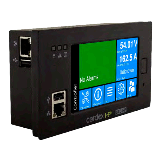
Summary of Contents for EnerSys Alpha Cordex CXC HP
- Page 1 Cordex® CXC HP Controller Modbus Integrator Guide User Guide ID: 0350114-J0 Effective: 01/2023 Read this document carefully. Learn how to protect your equipment from damage and fully understand its functions.
- Page 2 Copyright notice © 2023 Alpha Technologies Ltd., an EnerSys company. All Rights Reserved. Trademarks and logos are the property of EnerSys and its affiliates. Subject to revisions without prior notice. E.&O.E. No part of this documentation shall be reproduced, stored in a retrieval system, translated, transcribed, or transmitted in any form or by any means manual, electric, electronic, electromechanical, chemical, optical, or otherwise without prior explicit written permission from Alpha Technologies Ltd.
-
Page 3: Table Of Contents
Contents List of Figures............................... 3 List of Tables..............................4 1. Safety............................... 6 2. Introduction............................. 7 2.1. Overview............................7 2.2. Purpose and audience........................7 2.3. Knowledge and permissions......................7 3. Using Modbus............................8 3.1. Modbus capabilities on the Cordex® CXC HP controller.............. 8 3.2. Modbus setup..........................8 3.3. -
Page 4: List Of Figures
Modbus Integrator's Guide for the Cordex® CXC HP Controller List of Figures Figure 3-1 Enabling the Modbus agent......................9 Figure 3-2 Modbus connection configuration..................... 10 Figure 3-3 Modbus data example......................10 0350114-J0 Rev N Page 3... -
Page 5: List Of Tables
Modbus Integrator's Guide for the Cordex® CXC HP Controller List of Tables Table 3-1 Configuration..........................9 Table 3-2 Modbus address allocation for common controller data............11 Table 3-3 Modbus address allocation for DC system data................ 12 Table 3-4 Modbus address allocation for AMPS HP system data............. 12 Table 3-5 Controller data points......................... - Page 6 Modbus Integrator's Guide for the Cordex® CXC HP Controller Table 3-33 AMPS HP modular inverter system breakers/fuse data points..........41 Table 3-34 AMPS HP modular inverter system T2S data points............... 41 Table 3-35 AMPS HP modular inverter system TSI inverters data points..........41 Table 3-36 Limited data set data points.....................43 0350114-J0 Rev N Page 5...
-
Page 7: Safety
1. Safety SAVE THESE INSTRUCTIONS: This document contains important safety instructions that must be followed during the installation, servicing, and maintenance of the product. Keep it in a safe place. Review the drawings and illustrations contained in this document before proceeding. If there are any questions regarding the safe installation or operation of this product, contact Alpha Technologies Ltd. -
Page 8: Introduction
2. Introduction 2.1. Overview The purpose of this document is to provide information on how to use Cordex® CXC HP system controller and software along with Modbus. This document contains information on setup and operation of Modbus using the controller. 2.2. -
Page 9: Using Modbus
3. Using Modbus 3.1. Modbus capabilities on the Cordex® CXC HP controller A Modbus client connects to the controller over an Ethernet TCP/IP connection to request data. Modbus RTU is not directly supported, but third-party devices are available to translate from TCP/IP to RTU and vice versa. -
Page 10: Table 3-1 Configuration
Modbus Integrator's Guide for the Cordex® CXC HP Controller | 3 - Using Modbus Figure 3-1 Enabling the Modbus agent Table 3-1 Configuration Name Description Modbus Agent Enables or disables Modbus service. When enabled, the service is initialized and the controller is ready to accept requests. The controller serves data for both the limited and full data set. - Page 11 Modbus Integrator's Guide for the Cordex® CXC HP Controller | 3 - Using Modbus Figure 3-2 Modbus connection configuration Once a connection is made, data is polled automatically at the given device ID, address, and length as shown. Figure 3-3 Modbus data example Device ID: Provides specific data of interest for that device ID.
-
Page 12: Modbus Data
Modbus Integrator's Guide for the Cordex® CXC HP Controller | 3 - Using Modbus 3.3. Modbus data There are two types of data available over Modbus: limited data set and a full system data set for the DC system and each AMPS HP2 modular inverter system. 3.3.1. -
Page 13: Table 3-3 Modbus Address Allocation For Dc System Data
Modbus Integrator's Guide for the Cordex® CXC HP Controller | 3 - Using Modbus Table 3-3 Modbus address allocation for DC system data Source Maximum num- Start of coil sta- Start of input Start of values ber of source tus register (01) status register register (04) items... -
Page 14: How To Create An Identical Modbus Structure
Modbus Integrator's Guide for the Cordex® CXC HP Controller | 3 - Using Modbus Not all register addresses will be populated with data. For example, the controller does not actually have any coils (relays). A request for coil data at address 1 will return zero. The Modbus reference table on the controller web interface provides specific addresses for particular data points. -
Page 15: Modbus Reference
Modbus Integrator's Guide for the Cordex® CXC HP Controller | 3 - Using Modbus 1. Create your system and configure all it's inventory, custom data, timers, counters, user alarms, and ADIO module. 2. Name all your inventory (for example, shunts and loads), custom data, timers, counters, user alarms, and ADIO module with a number as a prefix. -
Page 16: Table 3-6 Custom Data Data Points
Modbus Integrator's Guide for the Cordex® CXC HP Controller | 3 - Using Modbus Table 3-5 Controller data points (continued) Name Register Format ADIO Comms Lost 02:Input Status Boolean Temporary License In Use 02:Input Status Boolean Temporary License Expired 02:Input Status Boolean Required Feature License Missing 02:Input Status... -
Page 17: Table 3-8 Counters Data Points
Modbus Integrator's Guide for the Cordex® CXC HP Controller | 3 - Using Modbus Table 3-8 Counters data points Name Register Format Down Counter: Input 02:Input Status Boolean Up Counter: Input 02:Input Status Boolean Down Counter: Output 04:Input Register 32-bit Floating Point Up Counter: Output 04:Input Register 32-bit Floating Point... -
Page 18: Table 3-11 Cordex® Cxc Hp 6I-Adio Data Points
Modbus Integrator's Guide for the Cordex® CXC HP Controller | 3 - Using Modbus Table 3-10 Cordex® CXC HP L-ADIO data points (continued) Name Register Format 02:Input Status Boolean 02:Input Status Boolean 02:Input Status Boolean 02:Input Status Boolean 02:Input Status Boolean 02:Input Status Boolean... -
Page 19: Table 3-12 Cordex® Cxc Hp Hv-Adio Data Points
Modbus Integrator's Guide for the Cordex® CXC HP Controller | 3 - Using Modbus Table 3-11 Cordex® CXC HP 6i-ADIO data points (continued) Name Register Format 04:Input Register 32-bit Floating Point 04:Input Register 32-bit Floating Point 04:Input Register 32-bit Floating Point 04:Input Register 32-bit Floating Point 04:Input Register... -
Page 20: Table 3-13 Cordex® I/M1 Adio Data Points
Modbus Integrator's Guide for the Cordex® CXC HP Controller | 3 - Using Modbus Table 3-12 Cordex® CXC HP HV-ADIO data points (continued) Name Register Format 04:Input Register 32-bit Floating Point 04:Input Register 32-bit Floating Point DCCT1 04:Input Register 32-bit Floating Point DCCT2 04:Input Register 32-bit Floating Point... -
Page 21: Table 3-15 Shunt Mux Adio Data Points
Modbus Integrator's Guide for the Cordex® CXC HP Controller | 3 - Using Modbus Table 3-14 PSU ADIO data points (continued) Name Register Format 01:Coil Status Boolean 01:Coil Status Boolean 02:Input Status Boolean 02:Input Status Boolean Temperature Sensor #1 Failure 02:Input Status Boolean Temperature Sensor #2 Failure... -
Page 22: Table 3-16 8R/8D Adio Data Points
Modbus Integrator's Guide for the Cordex® CXC HP Controller | 3 - Using Modbus Table 3-15 Shunt Mux ADIO data points (continued) Name Register Format 04:Input Register 32-bit Floating Point 04:Input Register 32-bit Floating Point 04:Input Register 32-bit Floating Point 04:Input Register 32-bit Floating Point Table 3-16 8R/8D ADIO data points... -
Page 23: Table 3-17 Bdfb Adio Data Points
Modbus Integrator's Guide for the Cordex® CXC HP Controller | 3 - Using Modbus Table 3-17 BDFB ADIO data points Name Register Format 01:Coil Status Boolean 01:Coil Status Boolean 01:Coil Status Boolean 01:Coil Status Boolean 01:Coil Status Boolean 01:Coil Status Boolean 01:Coil Status Boolean... -
Page 24: Table 3-18 E2 Adio Data Points
Modbus Integrator's Guide for the Cordex® CXC HP Controller | 3 - Using Modbus Table 3-17 BDFB ADIO data points (continued) Name Register Format 04:Input Register 32-bit Floating Point 04:Input Register 32-bit Floating Point 04:Input Register 32-bit Floating Point 04:Input Register 32-bit Floating Point 04:Input Register 32-bit Floating Point... -
Page 25: Table 3-19 Flexair® Adio Data Points
Modbus Integrator's Guide for the Cordex® CXC HP Controller | 3 - Using Modbus Table 3-18 E2 ADIO data points (continued) Name Register Format 02:Input Status Boolean 02:Input Status Boolean 02:Input Status Boolean 02:Input Status Boolean 02:Input Status Boolean 02:Input Status Boolean Temperature Sensor #1 Failure 02:Input Status... -
Page 26: Table 3-20 Smart Bypass Adio Data Points
Modbus Integrator's Guide for the Cordex® CXC HP Controller | 3 - Using Modbus Table 3-19 FlexAir® ADIO data points (continued) Name Register Format 04:Input Register 32-bit Floating Point 04:Input Register 32-bit Floating Point 04:Input Register 32-bit Floating Point 04:Input Register 32-bit Floating Point Fan 1 Speed 04:Input Register... -
Page 27: Table 3-21 Polarium Protocol Bridge Data Points
Modbus Integrator's Guide for the Cordex® CXC HP Controller | 3 - Using Modbus Table 3-20 Smart Bypass ADIO data points (continued) Name Register Format Inverter Phase L1 Current 04:Input Register 32-bit Floating Point Inverter Phase L2 Current 04:Input Register 32-bit Floating Point Inverter Phase L3 Current 04:Input Register... -
Page 28: Table 3-22 Dc System Data Points
Modbus Integrator's Guide for the Cordex® CXC HP Controller | 3 - Using Modbus Table 3-21 Polarium Protocol Bridge data points (continued) Name Register Format Lowest Full-Charging Voltage 04:Input Register 32-bit Floating Point Highest Charge Current Percent- 04:Input Register 32-bit Floating Point Highest Temperature 04:Input Register 32-bit Floating Point... - Page 29 Modbus Integrator's Guide for the Cordex® CXC HP Controller | 3 - Using Modbus Table 3-22 DC system data points (continued) Name Register Format Temp Comp Measurement Fail 02:Input Status Boolean (Deprecated) Temp Comp Voltage Warning (Dep- 02:Input Status Boolean recated) Battery Runtime Low 02:Input Status...
- Page 30 Modbus Integrator's Guide for the Cordex® CXC HP Controller | 3 - Using Modbus Table 3-22 DC system data points (continued) Name Register Format Estimated AC Phase 3 Voltage 04:Input Register 32-bit Floating Point Estimated Required Capacity 04:Input Register 32-bit Floating Point Estimated Available Capacity 04:Input Register 32-bit Floating Point...
-
Page 31: Table 3-23 Dc System Lead-Acid Battery Data Points
Modbus Integrator's Guide for the Cordex® CXC HP Controller | 3 - Using Modbus Table 3-23 DC system lead-acid battery data points Name Register Format Battery Charge Current High 02:Input Status Boolean Battery Temperature High 02:Input Status Boolean Battery Temperature Low 02:Input Status Boolean Battery Breaker/Fuse Open... -
Page 32: Table 3-25 Dc System Loads Data Points
Modbus Integrator's Guide for the Cordex® CXC HP Controller | 3 - Using Modbus Table 3-24 DC System Polarium battery data points (continued) Name Register Format Power 04:Input Register 32-bit Floating Point Battery Mode 04:Input Register 32-bit Floating Point This value corresponds to the mode of the battery as follows: •... -
Page 33: Table 3-26 Dc System Disconnects Data Points
Modbus Integrator's Guide for the Cordex® CXC HP Controller | 3 - Using Modbus Table 3-25 DC system loads data points (continued) Name Register Format Load: Load Voltage High 02:Input Status Boolean Load: Load Current High 02:Input Status Boolean Load: Load Breaker/Fuse Open 02:Input Status Boolean Load: Load Voltage Low... -
Page 34: Table 3-28 Dc System Current Transducer (Ct) Data Point
Modbus Integrator's Guide for the Cordex® CXC HP Controller | 3 - Using Modbus Table 3-28 DC system current transducer (CT) data point Name Register Format CT/397: Current 04:Input Register 32-bit Floating Point Table 3-29 DC system rectifiers data points Name Register Format... - Page 35 Modbus Integrator's Guide for the Cordex® CXC HP Controller | 3 - Using Modbus Table 3-30 AMPS HP modular inverter system data points (continued) Name Register Format Inverter Low Input Voltage 02:Input Status Boolean Brownout Inverter Fan Life Elapsed 02:Input Status Boolean Inverter Off 02:Input Status...
- Page 36 Modbus Integrator's Guide for the Cordex® CXC HP Controller | 3 - Using Modbus Table 3-30 AMPS HP modular inverter system data points (continued) Name Register Format System Mode 04:Input Register 32-bit Floating Point • Line = 1 • Inverter = 2 •...
- Page 37 Modbus Integrator's Guide for the Cordex® CXC HP Controller | 3 - Using Modbus Table 3-30 AMPS HP modular inverter system data points (continued) Name Register Format Supported by All Inverters 04:Input Register 32-bit Floating Point Expected DC Input Current in AC 04:Input Register 32-bit Floating Point Failure...
- Page 38 Modbus Integrator's Guide for the Cordex® CXC HP Controller | 3 - Using Modbus Table 3-30 AMPS HP modular inverter system data points (continued) Name Register Format Phase 2 Phase Power (VA) % of 04:Input Register 32-bit Floating Point Phase 2 Number Of Inverters On 04:Input Register 32-bit Floating Point Phase 2 Phase Power (W) % of...
- Page 39 Modbus Integrator's Guide for the Cordex® CXC HP Controller | 3 - Using Modbus Table 3-30 AMPS HP modular inverter system data points (continued) Name Register Format Phase 3 DC Input Power 04:Input Register 32-bit Floating Point Phase 3 Current Number Of Re- 04:Input Register 32-bit Floating Point dundant Inverters...
- Page 40 Modbus Integrator's Guide for the Cordex® CXC HP Controller | 3 - Using Modbus Table 3-30 AMPS HP modular inverter system data points (continued) Name Register Format AC Group 2 Number Of Inverters 04:Input Register 32-bit Floating Point Failed AC Group 3 Input Voltage 04:Input Register 32-bit Floating Point AC Group 3 Input Current...
- Page 41 Modbus Integrator's Guide for the Cordex® CXC HP Controller | 3 - Using Modbus Table 3-30 AMPS HP modular inverter system data points (continued) Name Register Format DC Group 2 Number Of Inverters 04:Input Register 32-bit Floating Point DC Group 2 Number Of Inverters 04:Input Register 32-bit Floating Point Failed...
-
Page 42: Table 3-31 Amps Hp Modular Inverter System Bypass Switch With Xmbs Data Points
Modbus Integrator's Guide for the Cordex® CXC HP Controller | 3 - Using Modbus Table 3-31 AMPS HP modular inverter system bypass switch with XMBS data points Name Register Format State 02:Input Status Boolean Bypass Active 02:Input Status Boolean Utility-Inverter Sync. Request Fault 02:Input Status Boolean Bypass Hardware Fault... - Page 43 Modbus Integrator's Guide for the Cordex® CXC HP Controller | 3 - Using Modbus Table 3-35 AMPS HP modular inverter system TSI inverters data points (continued) Name Register Format • Manual Off = 1 • Irrecoverable Error = 2 • Recoverable Error = 3 AC Input Status 04:Input Register 32-bit Floating Point...
-
Page 44: Limited Data Set Data Points
Modbus Integrator's Guide for the Cordex® CXC HP Controller | 3 - Using Modbus 3.5.2. Limited data set data points This section lists the available data points when using the limited data set. 3.5.2.1. Data points This section lists the Modbus data values available for the limited data set. Table 3-36 Limited data set data points Decimal ad- Register... - Page 45 Modbus Integrator's Guide for the Cordex® CXC HP Controller | 3 - Using Modbus Table 3-36 Limited data set data points (continued) Decimal ad- Register Name Format dress 30027 04:Input Register Battery: Average Temperature 32-bit Floating Point 30029 04:Input Register Battery: Current 32-bit Floating Point 30031...
-
Page 46: Glossary
4. Glossary Alternating current ACCT Alternating current current transducer ADIO Analog-digital input-output Alarm An alarm has user configurable fields like a name, priority, and it can is able to sent SNMP or email notifications when it becomes active or cleared. ALCO Alarm cutoff Alert... - Page 47 Modbus Integrator's Guide for the Cordex® CXC HP Controller | 4 - Glossary Media Access Control; MAC address Management Information Base; a database of entities most often associated with SNMP Metal oxide varistor Multiplexer NEBS Network Equipment-Building System; a set of safety, spatial and environmental guidelines for telecom OLED Organic light-emitting diode;...
- Page 48 For more information visit our website at: www.enersys.com © 2023 Alpha Technologies Ltd., an EnerSys company. All Rights Reserved. Trademarks and logos are the property of Alpha Technologies Ltd. and its affiliates. Subject to revisions without prior notice. E. & O.E.
Need help?
Do you have a question about the Alpha Cordex CXC HP and is the answer not in the manual?
Questions and answers