Advertisement
Quick Links
Advertisement

Related Manuals for KANG Industrial VS-300

Summary of Contents for KANG Industrial VS-300
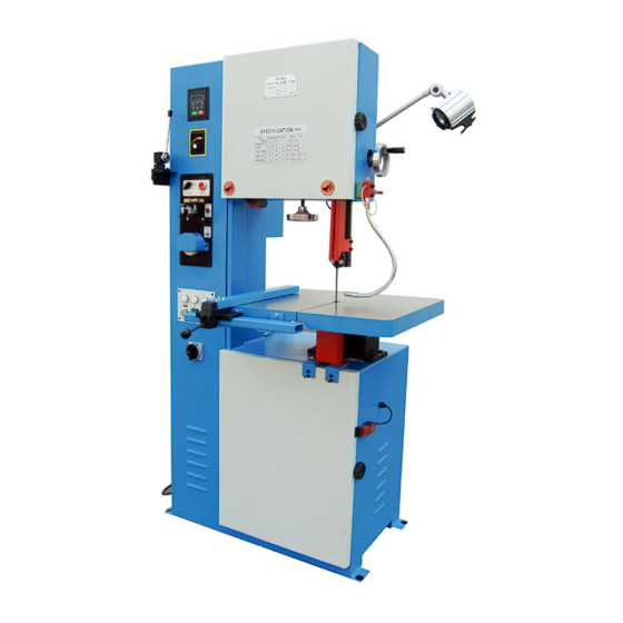
- Page 1 VERTICAL BAND SAW Model: VS-300/VS-400 VS-500/VS-585 Operating Manual...
-
Page 2: Table Of Contents
Table of contents I.INTRODUCTION……………………………………………………………….3 II.INFORMATION ABOUT MAINTENANCE ASSISTANCE…………………3 ……………………………………………………4 III. SPECIFICATION ……… 4 IV.DESCRIPTION OF THE MACHINE AND ITS COMPONENTS ………………………………………..5-10 V. INSTRUCTION MANUAL …………………………………………..11 VI.INVERTER PARAMETER VII. DRAWING AND PARTS LIST…………………………………………12-21 VIII.ELECTRICAL DRAWING FOR VS-400,VS-500 and VS-585…… .22-24... -
Page 3: I.introduction
I.INTRODUCTION The “Operating instructions” are an integral part of the machine and should be consulted before, during and after the start up of the machine and whenever else required. The content of these instructions should always be carefully observed. The observance of the above is the only way to achieve the two fundamental aims of this manual: ●... -
Page 4: Specification
III. SPECIFICATION Item No. 388200 388201 388202 388203 Model VS-300 VS-400 VS-500 VS-585 310mm(12.2”) 336mm(13.2”) Max.Cutting Height 185mm(7.3”) 285mm(11.2”) 400mm (15.7”) 500mm(19.7”) 585mm(23”) capacity Width 310mm (12.2”) Table Size 500x400mm 550x600mm 660x700mm 660x700mm (21.7”x23.6”) (26”x27.6”) (26”x27.6”) (19.7”x15.7”) Blade 10-180m/min 15-260m/min... -
Page 5: Instruction Manual
button. The control lever,fitted with an ergonomic hand-grip and activation button with safety release action, reduces fatigue during operation to a minimum. The blade is protected by a guard with interlock which covers the upper area and the hand wheels and by two adjustable lower guards which protect the operator from ejected shavings and coolant. - Page 6 ACTION TAKEN A. Power 1. First, before operating the machine, be sure to check the voltage which is in accordance with the power supply system. B. Sawing Material Selection: Before sawing, the operator must fully understand the quality of the sawing material. Example: With super high stencil steel, the machine should be run at a slower speed.
- Page 7 position. 2. Welding operation a. Use your Thumb to press the Welding Button, then blade change to Red color and activities electrode driven the blade feed for welding. Please do not release the Weld Button during the welding until the blade back to black color. 3.
- Page 8 Maintenance and trouble shooting 1. Maintenances a. put the voltage adj. knob back to mark of “i” when the machine is not working b. after half hour working, the machine can only be continute to work when the temperature is lowing down to the ambient temperature 2.
- Page 9 separate the second touch point. According to the time of welding needed to adjust the distance A. The bigger distance in A, the longer time for welding melt. Trouble Possible Reason Solution Welding a. Blades welding end is dirty a. Cleaning the blades with clothes. seam broken b.
- Page 10 The grinder is used for grinding off both ends of the cut blade on the surface so that the blade can be welded together easily. Note: Do not exceed in running the grinder for more than 30 minutes at a time. G.
-
Page 11: Vi.inverter Parameter
blade through. Weld the blade ends together (grinding smooth). Reinstall blade on wheels and make normal blade adjustment. Begin to perform contour sawing. 5. Working Speed: When sawing, the speed shall remain the same (neither fast nor slow); otherwise, blade breaking may occur. M. - Page 12 Continuous welding should be avoided. After being used several times, turn the welder off for 15 minutes rest so that the transformer will not suffer from overheat. In case that transformer becomes overheated, the temperature controller will actuate the breaker. Reuse will not be allowed until the transformer cools down.
-
Page 13: Drawing And Parts List
VII. DRAWING AND PARTS LIST VS-300 and VS-400 packing list and drawing Item Description Item Description Low door Wood brush Bolt M6X12 Bolt M5X20 Nut M6 Big washer 5 Block Bolt M5X16 Blade block material seat Washer 5 Blade stay bar... - Page 14 Item Description Item Description Bolt M6X12 Flange Handle wheel Bearing 6206-2Z Bolt M6X6 Block 62 Elasticity pin 2X14 Handle Gear seat Bearing 51201 Bolt M6X25 Bolt washer Big washer 6 Elasticity pin 3X24 Worm Lead Screw Washer Bolt M8X25 Bolt washer Washer 8 Slanting gear Shaft seat...
- Page 18 VS-500 and VS-585 packing list and drawing Item Description Item Description Low door Water box Bolt M6X12 Wood brush Nut M6 Bolt M5X20 Big washer 5 Bolt M5X16 Block Washer 5 Blade block material seat Left seat board 43.1 Spring pin 3X18 Right seat board Blade stay bar Bolt M6X8...
- Page 19 Item Description Item Description Gate Motor Bolt M8X16 Belt A-1750 Rack Big saw wheel Blade protect cover 113.1 Bracket Washer 6 Bolt M8X25 Bolt M6X12 Flat key 12X50 Handle wheel Checking ring 40 Bolt M6X6 Low wheel shaft Elasticity pin 3X14 Bolt M12X55 Gear seat Leveling bolt...
- Page 20 24(4) 25(4) 27(6) 18(4) 28(6) 16(2) 15(6) 32(2) 34(12) 35(12) 11(4) 9(2) 6(4) 5(4) 3(2) 36(2) 37(2) 4(4) 2(2)
- Page 21 94(2) 85 86 87 83(2) 82(2) 73(2) 80(2) 77(4) 76(4) 71(4) 70(4) 68.1 64(2) 63(2) 58(4) 45(2) 44(2) 46(2) 43(2) 42(4) 41(4) 40(4) 54(4) 53(4) 52(8) 43.1(2) 52.1(4)
- Page 22 137(2) 138(8) 135(2) 134(2) 141(2) 131(2) 130(2) 128(2) 127(2) 126(2) 113.1 118(4) 119(4) 121(2) 122(2) 115(2) 114(4) 112(2) 102(2) 110(2) 105(4) 106(4) 108(2) 109(2)
-
Page 23: Viii.electrical Drawing For Vs-400,Vs-500 And Vs-585
VIII.ELECTRICAL DRAWING FOR VS-400,VS-500 and VS-585... - Page 26 Note: This manual is only for your reference. Owing to continuous improvement of the machines, Changes may be made at any time without obligation on notice.
Need help?
Do you have a question about the VS-300 and is the answer not in the manual?
Questions and answers