Table of Contents
Advertisement
Quick Links
Thank you for your purchase of the Robot Power Wasp™ motor control. This manual
explains the features and functions of the Wasp along with some tips for successful
application. Before using your Wasp you must read and agree to the disclaimer printed at the
end of this document. If you don't agree please return your unused Wasp to Robot Power for
a refund.
The Robot Power Wasp is a low-cost, easy to connect power amplifier designed to work with
DC motors, lights, solenoids and other low-voltage DC loads. The Wasp is configured as a
single H-bridge circuit and allows bi-directional control of a single motor or other load. While
designed for permanent magnet brushed DC motors; the Wasp is suitable for a wide range of
DC loads as long as they are within the current and voltage envelope of the device.
1. Specifications
Wasp User Manual
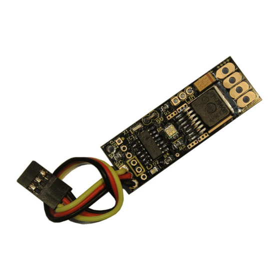
Figure 1. Wasp top view
Voltage Range
6V – 24V (28V absolute max)
10A cont. at 100% duty cycle
Current
9A cont. at 70%
30A - 5 second peak
PWM frequency
3.9kHz
Over-Current and
Over-Temp
Built-in
Protection
Input voltage
2.5V – 5.5V = logic high
1
1
Version 1.0 - May 26, 2011
Advertisement
Table of Contents

Related Manuals for Robot Power WASP

Summary of Contents for Robot Power WASP
- Page 1 Wasp along with some tips for successful application. Before using your Wasp you must read and agree to the disclaimer printed at the end of this document. If you don’t agree please return your unused Wasp to Robot Power for a refund.
- Page 2 Figure 2 shows the Wasp unit with its available connections. Figure 2. Wasp connections To use the Wasp, connect the RC connector to an RC signal source such as an RC receiver or to a microcontroller unit programmed to generate servo pulses. The polarity of the connector is shown.
- Page 3 LED Indicators The Wasp has two LEDs used for visual indication of the state of the unit. The Status LED is green and shows the status of the RC signal to the unit. If the Status LED is blinking either the RC input signal is absent or out of the legal range.
- Page 4 Following is the calibration sequence: 1) Power on the Wasp either with the main battery or through the RC cable. The status LED should be solid showing the Wasp is locked to the input signal. A motor does not need to be connected.
- Page 5 When the load hits the end of the track and closes the switch the Wasp cuts off the motor in that direction. The load may still be driven in the other direction to move away from the switch and the end of the track.
- Page 6 5.0V regulated output voltage is large. If the voltage regulator gets too hot it will shut off to prevent damage. This disables the Wasp since the internal CPU uses the output of the regulator. The Wasp has been tested up to 21V input without overloading the regulator.
- Page 7 The Robot Power Team Disclaimer: The Wasp is intended for educational and experimental uses. It should not be used in applications where human life or health or significant property value depend on its proper operation. Robot Power is not responsible for any loss or damage incurred by the operation or failure of this unit.
Need help?
Do you have a question about the WASP and is the answer not in the manual?
Questions and answers