Advertisement
Quick Links
SERVICE MANUAL
TECHNICAL INFORMATION
FOR SERVICE PERSONNEL ONLY
RAC-70NPD
SPECIFICATIONS
TYPE
MODEL
POWER SOURCE
TOTAL INPUT
TOTAL AMPERES
COOLING
CAPACITY
TOTAL INPUT
TOTAL AMPERES
HEATING
CAPACITY
DIMENSIONS
(mm)
NET WEIGHT
SPECIFICATIONS AND PARTS ARE SUBJECT TO CHANGE FOR IMPROVEMENT
ROOM AIR CONDITIONER
SEPTEMBER 2017
RAD-70PPD
OPTIONAL
WIRED REMOTE
CONTROLLER
(SPX-RCDA)
WIRELESS REMOTE
CONTROLLER
(SPX-RCKA1)
WIRED REMOTE
CONTROLLER
(SPX-WKT3)
※
For SPX-WKT3, Please refer to it's
own manual.
INDOOR UNIT
RAD-70PPD
(W)
(A)
(kW)
(B.T.U./h)
(W)
(A)
(kW)
(B.T.U./h)
W
H
D
(kg)
INDOOR UNIT + OUTDOOR UNIT
Refrigeration & Air-Conditioning Division
NO. 0630E
PM
RAD-70PPD/RAC-70NPD
REFER TO THE FOUNDATION MANUAL
SPECIFICATIONS ------------------------------------------------------ 5
HOW TO USE ---------------------------------------------------------- 8
CONSTRUCTION AND DIMENSIONAL DIAGRAM ---------52
MAIN PARTS COMPONENT --------------------------------------55
WIRING DIAGRAM ---------------------------------------------------57
CIRCUIT DIAGRAM --------------------------------------------------62
BLOCK DIAGRAM ----------------------------------------------------72
BASIC MODE ----------------------------------------------------------74
REFRIGERATING CYCLE DIAGRAM---------------------------88
DESCRIPTION OF MAIN CIRCUIT OPERATION -----------89
SERVICE CALL Q & A --------------------------------------------108
TROUBLE SHOOTING --------------------------------------------145
PARTS LIST AND DIAGRAM ------------------------------------ 146
(DUCT TYPE)
1 Ø, 50/60 Hz, 220-240V
2,110 (500 ~ 2,700)
9.69 – 8.88
7.00 (1.50 ~ 8.00)
23,880 (5,110 ~ 27,290)
2,200 (500 ~ 2,800)
10.10– 9.26
8.00 (1.50 ~ 8.50)
27,290 (5,110 ~ 29,000)
900
270
720
35
CONTENTS
OUTDOOR UNIT
RAC-70NPD
850
800
298
52
After installation
Advertisement

Related Manuals for Hitachi RAC-70NPD


Summary of Contents for Hitachi RAC-70NPD
- Page 1 NO. 0630E RAD-70PPD/RAC-70NPD SERVICE MANUAL TECHNICAL INFORMATION REFER TO THE FOUNDATION MANUAL FOR SERVICE PERSONNEL ONLY CONTENTS SPECIFICATIONS ------------------------------------------------------ 5 RAD-70PPD HOW TO USE ---------------------------------------------------------- 8 CONSTRUCTION AND DIMENSIONAL DIAGRAM ---------52 MAIN PARTS COMPONENT --------------------------------------55 OPTIONAL WIRING DIAGRAM ---------------------------------------------------57 CIRCUIT DIAGRAM --------------------------------------------------62...
- Page 6 RAC-70NPD RAD-70PPD 450NR 1600g R32)
- Page 8 Figure showing the installation of Outdoor unit Be sure to completely seal any gap WARNING above 100mm with putty. Flare connection only at outside of building The indoor piping should be insulated with the enclosed insulation pipe. (If the insulator is Refrigerant piping insuffi...
- Page 11 RAC-70NPD RAD-70PPD RAC-70NPD...
- Page 18 RAR-6N1 RAR-6N2 RAR-6N3 RAR-6N4 RAR-6N5...
- Page 21 / dimming...
- Page 28 PREPARATION BEFORE OPERATION ■ To install the batteries 1. Slide the cover to take it off. 2. Install two dry batteries AAA.LR03 (alkaline). The direction of the batteries should match the marks in the case. 3. Replace the cover at its original position. ■...
- Page 29 PREPARATION BEFORE OPERATION ■ To set calendar and clock 1. Press (RESET) button when fi rst time setting. "Year" blinks. 2. Press (TIME) button to set the current year. 3. Press (CLOCK) button. "Day" and "Month" blink. 4. Press (TIME) button to set the current day and month.
- Page 30 NAMES AND FUNCTIONS OF REMOTE CONTROLLER REMOTE CONTROLLER This controls the operation of the indoor unit. The range of control is about 7 meters. If indoor lighting ● is controlled electronically, the range of control may be shorter. This unit can be fi xed on a wall using the fi xture provided. Before fi xing it, make sure the indoor unit can be controlled from the remote controller.
- Page 31 NAMES AND FUNCTIONS OF REMOTE CONTROLLER MODE selector Button POWERFUL Button Use this button to select the Use this button to set the operating mode. Every time you POWERFUL mode. ( p. 11) press this button, the mode will (AUTO) ➞ change from (HEAT) ➞...
- Page 32 VARIOUS FUNCTIONS ■ Auto Restart Control If there is a power failure, operation will be automatically restarted when the power is resumed with previous operation ● mode and airfl ow direction. (As the operation is not stopped by remote controller.) If you intend not to continue the operation when the power is resumed, switch off the power supply.
- Page 33 HEATING OPERATION Use the device for heating when the outdoor temperature is under 21°C. ● When it is too warm (over 21°C), the heating function may not work in order to protect the device. In order to maintain reliability of the device, please use this device when outdoor temperature is above ●...
- Page 34 DEHUMIDIFYING OPERATION Use the device for dehumidifying when the room temperature is over 16°C. When it is under 15°C, the dehumidifying function will not work. Press the MODE selector button so that the display indicates (DEHUMIDIFY). The fan speed is set at LOW. Press (FAN SPEED) button to select SILENT or LOW fan speed.
- Page 35 COOLING OPERATION Use the device for cooling when the outdoor temperature is -10~ 43°C. If indoors humidity is very high (80%), some dew may form on the air outlet grille of the indoor unit. Press the MODE selector button so that the display indicates (COOL).
- Page 36 FAN OPERATION User can use the device simply as an air circulator. Press the MODE selector so that the display indicates (FAN). Set the desired FAN SPEED with the (FAN SPEED) button (the display indicates the setting). (HIGH) (MED) (LOW) (SILENT) START Press the...
- Page 37 POWERFUL OPERATION By pressing (POWERFUL) button during AUTO, HEATING, DEHUMIDIFYING, COOLING or FAN ● operation, the air conditioner performs at the maximum power. During POWERFUL operation, cooler or warmer air will be blown out from indoor unit for COOLING or ●...
- Page 38 SILENT OPERATION By pressing (SILENT) button during AUTO, HEATING, DEHUMIDIFYING, COOLING or FAN operation, ● the fan speed will change to ultra slow. ■ To start SILENT operation Press (SILENT) button during operation. ● “ ” is displayed on the LCD. Fan speed will be ultra slow. ■...
- Page 39 ECO OPERATION ECO operation is an energy saving function by changing set temperature automatically and by limiting the maximum power consumption value. By pressing the (ECO) button during AUTO, HEATING, ● DEHUMIDIFYING or COOLING operation, the air conditioner performs the "ECO" operation. ■...
- Page 40 – 39 –...
- Page 41 CLEAN (ONE TOUCH CLEAN) OPERATION Drying indoor heat exchanger after cooling operation to prevent mildew. ■ To start CLEAN operation Press (CLEAN) button when unit is OFF. ● Total time taken for One Touch Clean operation is 60 minutes. During this operation, HEATING or FAN operation shall operate.
- Page 42 ONCE TIMER (ON/OFF TIMER) OPERATION OFF TIMER The device can be set to turn off at a preset time. 1. Press (OFF-TIMER) button. blink on the display. 2. Set the "turn-off time" with (TIME) button. 3. After setting, direct the remote controller towards the indoor and press (SEND) button.
- Page 43 ECO SLEEP TIMER OPERATION The timer can be set up to a duration of 7 hours. By pressing (SLEEP) button during AUTO, HEATING, DEHUMIDIFYING, COOLING or FAN operation, the unit shifts the room temperature and reduces the fan speed. It results in energy saving. Set the current time fi...
- Page 44 ECO SLEEP TIMER OPERATION ■ To set ECO SLEEP TIMER and ON TIMER The air conditioner will be turned off by ECO SLEEP TIMER and turned on by ON TIMER. 1. Set the ON TIMER. 2. Press (SLEEP) button and set ECO SLEEP TIMER. Example: In this case, air conditioner will turn off in 2 hours (at 1:38) and it will be turned on at 6:00 the next morning.
- Page 45 WEEKLY TIMER OPERATION It is possible to select Mode A or Mode B. For each mode, up to 6 programs can be set per day. In total, a ● maximum of 42 programs can be set for a week for each mode. If calendar and clock are not set, the reservation setting for WEEKLY TIMER cannot be set.
- Page 46 WEEKLY TIMER OPERATION 5. Press (ON-OFF TIMER) button to select ON TIMER or OFF TIMER reservation. 6. Press (TIME) button to set time reservation. 7. Press (TEMP ) button to set temperature reservation. 8. Press (OK) button. The reservations are set. Day, program number, ON reservation, setting temperature will light up.
- Page 47 WEEKLY TIMER OPERATION Step 2: Select Mode A or Mode B and activate or deactivate WEEKLY TIMER. ■ How to select Mode A or Mode B of WEEKLY TIMER setting. 1. Press (WEEKLY) button. blink on the display. (Normally Mode A will blink fi rst). 2.
- Page 48 WEEKLY TIMER OPERATION Step 3: Copy and cancel the reservation schedule. ■ How to copy and paste. Editing the reservation schedule is easy by copying data from one day to another day. 1. Press (WEEKLY) button to select Mode A or Mode B. 2.
- Page 49 WEEKLY TIMER OPERATION Step 3: Copy and cancel the reservation schedule. ■ How to delete WEEKLY TIMER data. [Delete one program number reservation] 1. Press (WEEKLY) button to select Mode A or Mode B. 2. Press (WEEKLY) button for 3 seconds to start editing the reserva- tion schedule.
- Page 50 WEEKLY TIMER OPERATION Step 3: Copy and cancel the reservation schedule. [Delete one day reservation] 1. Press (WEEKLY) button to select Mode A or Mode B. 2. Press (WEEKLY) button for 3 seconds to start editing the reservation schedule. 3. Press (DAY) button to select a day of the week to edit.
- Page 51 INFO FUNCTION ● By pressing (INFO) button, temperature around remote controller and monthly power consumption will be displayed on the remote controller. ● After changing the batteries, direct the remote controller towards the indoor unit and press (INFO) button. Current calendar and clock will be transmitted from indoor unit. ●...
- Page 52 OPERATION MODE LOCK The remote controller can be set to fi x the HEATING mode (including FAN), COOLING mode (including FAN) and DEHUMIDIFYING mode (including FAN) operations. ■ Method to lock HEATING mode (including FAN) operation. Press (ECO) and (POWERFUL) buttons simultaneously for about 5 seconds when the remote controller is OFF.
- Page 53 CONSTRUCTION AND DIMENSIONAL DIAGRAM MODEL RAD-70PPD Note: 1. Servicing space of 100mm or more is required on the left and right sides of the indoor unit and also 50mm or more space is required above the unit 2. Insulated pipes should be used for both the narrow and wide dia. pipes. 3.
- Page 54 RAD-70PPD...
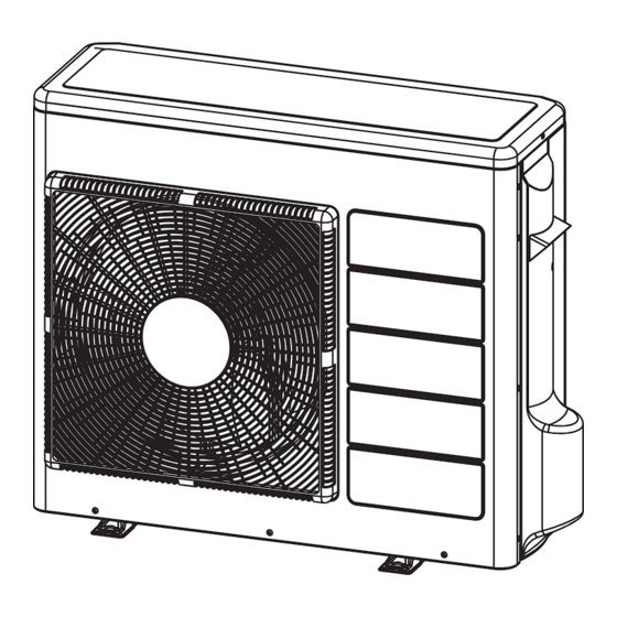
- Page 55 RAC-70NPD Handle Handle Air Outlet Air suction grille Holes for anchor bolt ( 2- 12 ) Fixing Hole Notch for anchor bolt ( 2- 12 Notchs ) More than More than Service Space...
- Page 56 INDICATION °C (°F) 23.3 (73.9) 28.7 (83.7) 31.6 (88.9) 36.0 (96.8) INDICATION 31.3 (88.3) 36.7 (98.1) FAN MOTOR Fan Motor Specifi cations RAC-70NPD RAD-70PPD MODEL POWER SOURCE DC: 310V DC120~380V OUTPUT 180W CONNECTION (Control circuit built in) BLU : BLUE...
- Page 57 RAC-70NPD...
- Page 58 MODEL RAD-70PPD / RAC-70NPD INDOOR DRAIN PUMP M FAN MOTOR MOTOR IPM P.W.B CN21(BLU) JOINT WIRED REMOTE P(+) N(-) COMPRESSOR CAPA P.W.B CONNECTOR RUN STATUS HA / CARD-KEY CONTROLLER 3 1 DRAIN PUMP RELAY CN12 CN25 CN1102 OUTDOOR TERMINAL CN22(BLU) 3.15A...
- Page 61 INDOOR FAN MOTOR T001(SW TRANS) CN12 C204 GRN1 RESISTOR CAPACITOR CONNECTOR VALUE POWER ASSY. VALUE VOLT ASSY. ASSY. C907 FORM PCBA GROUP REMARK TYPE FORM PCBA CHAR GROUP REMARK MODEL FORM GROUP PCBA REMARK C205 (Ω) R62 10k 5% 1/10 1608 B2B-PH-K-K 157 ROOM THERM...
- Page 62 MODEL : RAC-70NPD REACTOR TAB7 TAB5 MOUNTING FOARMING A : AXIAL INSERTION R : RADIAL INSERTION P : RADIAL INSERTION (7.5mm pitch) H : HAND INSERTION C : CHIP FOR ACT MOUNTING BOARD H : HIC PCB (#HIC-BOARD) CIRCUIT TO DETECT...
- Page 63 MODEL : RAC-70NPD REACTOR TAB7 TAB5 COMPR motor C915 R009 MOUNTING FOARMING A : AXIAL INSERTION R : RADIAL INSERTION P : RADIAL INSERTION (7.5mm pitch) H : HAND INSERTION DRIVER CIRCUIT C : CHIP FOR ACT R905 MOUNTING BOARD...
- Page 64 RAD-70PPD ‒ 68 ‒...
- Page 65 ‒ 69 ‒...
- Page 68 ‒ 72 ‒...
- Page 69 RAD-70PPD...
- Page 72 Lo/Silent (2) The indoor fan is operated in the "Lo" or "Silent" mode. During thermo OFF, indoor fan will be OFF 5 minutes and ON for 1 minute...
- Page 77 ECO Operation (With Motion Sensor) In the room Cooling / Heating period In the room period Absent period operation ECO button press Remocon Signal Operation lamp Human sensor No signal No signal Pulse signal Absent flag In the room Timer [MNONTM] [MANON1] [MANOF1]...
- Page 78 RAD-70PPD / RAC-70NPD REFRIGERATING CYCLE DIAGRAM COOLING, DEHUMIDIFYING, DEFROSTING INDOOR UNIT OUTDOOR UNIT CONDENSOR COMPRESSOR S-TANK REV-VALVE 5S VALVE (15.88mm)(5/8") THERMISTOR EXPANSION VALVE 2S VALVE (6.35mm)(1/4") STRAINER HEATING INDOOR UNIT OUTDOOR UNIT CONDENSOR COMPRESSOR S-TANK REV-VALVE 5S VALVE (15.88mm)(5/8") THERMISTOR...
- Page 79 RAD-70PPD ‒ 89 ‒...
- Page 80 IC733 ‒ 90 ‒...
- Page 81 ‒ 91 ‒...
- Page 82 L801 R804 C804 R803 Outdoor reception circuit Outdoor transmitting circuit Q203 Outdoor microcomputer Outdoor reception input Outdoor transmission output ‒ 92 ‒...
- Page 84 R621 ‒ 94 ‒...
- Page 85 IC733 ‒ 95 ‒...
- Page 86 ‒ 96 ‒...
- Page 87 R297 R282 ‒ 97 ‒...
- Page 88 12-1 12-1 12-2 – 98 –...
- Page 89 MODEL RAC-70NPD – 99 –...
- Page 92 4. Reversing valve control circuit This model reversing valve control used to control the relay ON/OFF of the reversing valve, and also control the coil of the reversing valve ON/OFF. The relay ON/OFF has different type when in the different operation mode. You can see each operation mode as follows.
- Page 101 ‒ 111 ‒...
- Page 102 RAC-70NPD ‒ 112 ‒...
- Page 103 – 113 –...
- Page 104 – 114 –...
- Page 105 – 115 –...
- Page 106 – 116 –...
- Page 107 – 117 –...
- Page 108 – 118 –...
- Page 109 – 119 –...
- Page 110 – 120 –...
- Page 111 – 121 –...
- Page 112 – 122 –...
- Page 113 – 123 –...
- Page 114 – 124 –...
- Page 115 – 125 –...
- Page 116 – 126 –...
- Page 117 – 127 –...
- Page 118 – 128 –...
- Page 119 – 129 –...
- Page 120 – 130 –...
- Page 122 – 132 –...
- Page 129 RAR-5E1, RAR-5E2, RAR-5E3, RAR-5E4, RAR-5E5, RAR-6N1, RAR-6N2, RAR-6N3, RAR-6N4 and RAR-6N5)
- Page 135 SUMMARY OF TROUBLESHOOTING METHOD FOR OUTDOOR UNIT Test Run MODEL : RAC-70NPD 1) Remove Terminal 3 connection. Checking the fan motor Checking the IPM IC of IPM P.W.B. 2) Power ON the unit and winding. 1) Power off the unit.
- Page 136 PARTS LIST AND DIAGRAM INDOOR UNIT MODEL : RAD-70PPD - 146 -...
- Page 137 RAD-70PPD MODEL PART NUMBER Q'TY / UNIT DESCRIPTION PMRAD-50DH7 DRAIN PAN ASSY PMRAD-50DH7 FIOAT SWITCH PMRAD-50DH7 FAN CASING PMRAD-50DH7 FAN COVER PMRAD-50DH7 BAND (L) PMRAD-50DH7 BAND (R) PMRAD-50DH7 DRAIN PUMP PMRAD-50DH7 FILTER PMRAD-50DH7 FILTER PLATE PMRAD-50DH7 THERMISTOR SUPPORT PMRAD-50DH7 ROOM THERMISTOR PMRAD-50DH7 THERMISTOR PMRAD-70PPD...
- Page 138 MODEL RAC-70NPD -136-...
- Page 139 MODEL RAC-70NPD DESCRIPTION RAC-70NPD PMKPNT1 PUSH NUT PMRAC-2226HV COMPRESSOR RUBBER PMRAC-25NH4 OVERHEAT THERMISTOR SUPPORT PMRAC-25NPA ELECTRICAL EXPANSION COIL EXPANSION VALVE PMRAC-25NPA PMRAC-30MH1 TOP COVER PMRAC-50NH4 VALVE (2S) COMPRESSOR PMRAC-50NPD PMRAC-50YHA2 REACTOR THERMISTOR (OUTSIDE TEMPERATURE) PMRAC-50YHA2 IPM BOARD PMRAC- 50YHA4 PMRAC-50YHA4...
- Page 140 HITACHI RAD-70PPD/RAC-70NPD PM NO. O630E Printed in Malaysia...
Need help?
Do you have a question about the RAC-70NPD and is the answer not in the manual?
Questions and answers