
Related Manuals for Daikin VRV IV+ RXYTQ8U5YF


Summary of Contents for Daikin VRV IV+ RXYTQ8U5YF
- Page 1 Installer and user reference guide VRV IV+ heat pump for high ambient temperatures RXYTQ8U5/U7YF RXYTQ10U5/U7YF RXYTQ12U5/U7YF RXYTQ14U5/U7YF RXYTQ16U5/U7YF...
-
Page 2: Table Of Contents
Table of contents Table of contents 1 About the documentation About this document ..............................Meaning of warnings and symbols..........................2 General safety precautions For the installer ................................2.1.1 General ................................2.1.2 Installation site ............................... 2.1.3 Refrigerant — in case of R410A or R32......................2.1.4 Electrical ................................. - Page 3 13 Technical data 13.1 Eco Design requirements..............................46 For the installer 14 About the box 14.1 About LOOP BY DAIKIN ..............................48 14.2 Overview: About the box ..............................48 14.3 To unpack the outdoor unit............................49 14.4 To remove the accessories from the outdoor unit ......................50 14.5...
- Page 4 Table of contents 17.2.11 To remove the spun pipes..........................77 17.3 Checking the refrigerant piping............................78 17.3.1 About checking the refrigerant piping ......................78 17.3.2 Checking refrigerant piping: General guidelines ................... 79 17.3.3 Checking refrigerant piping: Setup ........................ 80 17.3.4 To perform a leak test ............................
- Page 5 Table of contents 24 Disposal 25 Technical data 25.1 Service space: Outdoor unit ............................134 25.2 Piping diagram: Outdoor unit ............................136 25.3 Wiring diagram: Outdoor unit ............................137 26 Glossary RXYTQ Installer and user reference guide VRV IV+ heat pump for high ambient temperatures 4P561157-1B –...
-
Page 6: About The Documentation
The original documentation is written in English. All other languages are translations. Technical engineering data ▪ A subset of the latest technical data is available on the regional Daikin website (publicly accessible). ▪ The full set of latest technical data is available on the Daikin Business Portal (authentication required). - Page 7 About the documentation DANGER: RISK OF ELECTROCUTION Indicates a situation that could result in electrocution. DANGER: RISK OF BURNING/SCALDING Indicates a situation that could result in burning/scalding because of extreme hot or cold temperatures. DANGER: RISK OF EXPLOSION Indicates a situation that could result in explosion. WARNING Indicates a situation that could result in death or serious injury.
-
Page 8: General Safety Precautions
Improper installation or attachment of equipment or accessories could result in electrical shock, short-circuit, leaks, fire or other damage to the equipment. ONLY use accessories, optional equipment and spare parts made or approved by Daikin. WARNING Make sure installation, testing and applied materials comply with applicable legislation (on top of the instructions described in the Daikin documentation). -
Page 9: Installation Site
General safety precautions CAUTION ▪ Do NOT place any objects or equipment on top of the unit. ▪ Do NOT sit, climb or stand on the unit. In accordance with the applicable legislation, it might be necessary to provide a logbook with the product containing at least: information on maintenance, repair work, results of tests, stand-by periods,…... - Page 10 General safety precautions WARNING Take sufficient precautions in case of refrigerant leakage. If refrigerant gas leaks, ventilate the area immediately. Possible risks: ▪ Excessive refrigerant concentrations in a closed room can lead to oxygen deficiency. ▪ Toxic gas might be produced if refrigerant gas comes into contact with fire. DANGER: RISK OF EXPLOSION Pump down –...
-
Page 11: Electrical
General safety precautions Then A siphon tube is present Charge with the cylinder upright. (i.e., the cylinder is marked with "Liquid filling siphon attached") A siphon tube is NOT present Charge with the cylinder upside down. ▪ Open refrigerant cylinders slowly. ▪... - Page 12 General safety precautions WARNING ▪ ONLY use copper wires. ▪ Make sure the field wiring complies with the applicable legislation. ▪ All field wiring MUST be performed in accordance with the wiring diagram supplied with the product. ▪ NEVER squeeze bundled cables and make sure they do NOT come in contact with the piping and sharp edges.
- Page 13 General safety precautions WARNING ▪ After finishing the electrical work, confirm that each electrical component and terminal inside the electrical components box is connected securely. ▪ Make sure all covers are closed before starting up the unit. NOTICE ONLY applicable if the power supply is three‑phase, and the compressor has an ON/ OFF starting method.
-
Page 14: Specific Installer Safety Instructions
Specific installer safety instructions 3 Specific installer safety instructions Always observe the following safety instructions and regulations. WARNING Tear apart and throw away plastic packaging bags so that nobody, especially children, can play with them. Possible risk: suffocation. CAUTION Appliance NOT accessible to the general public, install it in a secured area, protected from easy access. - Page 15 Specific installer safety instructions WARNING NEVER remove the spun piping by brazing. Any gas or oil remaining inside the stop valve may blow off the spun piping. WARNING ▪ ONLY use R410A as refrigerant. Other substances may cause explosions and accidents.
- Page 16 Specific installer safety instructions CAUTION ▪ When connecting the power supply: connect the earth cable first, before making the current-carrying connections. ▪ When disconnecting the power supply: disconnect the current-carrying cables first, before separating the earth connection. ▪ The length of the conductors between the power supply stress relief and the terminal block itself MUST be as such that the current-carrying wires are tautened before the earth wire is in case the power supply is pulled loose from the stress relief.
-
Page 17: For The User
For the user RXYTQ Installer and user reference guide VRV IV+ heat pump for high ambient temperatures 4P561157-1B – 2021.11... -
Page 18: User Safety Instructions
User safety instructions 4 User safety instructions Always observe the following safety instructions and regulations. In this chapter General....................................Instructions for safe operation............................... 4.1 General WARNING If you are NOT sure how to operate the unit, contact your installer. WARNING This appliance can be used by children aged from 8 years and above and persons with reduced physical, sensory or mental capabilities or lack of experience and knowledge if... -
Page 19: Instructions For Safe Operation
User safety instructions ▪ Units are marked with the following symbol: This means that electrical and electronic products may NOT be mixed with unsorted household waste. Do NOT try to dismantle the system yourself: the dismantling of the system, treatment of the refrigerant, of oil and of other parts MUST be done by an authorised installer and MUST comply with applicable legislation. - Page 20 User safety instructions CAUTION To avoid oxygen deficiency, ventilate the room sufficiently if equipment with burner is used together with the system. WARNING This unit contains electrical and hot parts. WARNING Before operating the unit, be sure the installation has been carried out correctly by an installer.
- Page 21 User safety instructions WARNING ▪ Do NOT modify, disassemble, remove, reinstall or repair the unit yourself as incorrect dismantling or installation may cause an electrical shock or fire. Contact your dealer. ▪ In case of accidental refrigerant leaks, make sure there are no naked flames.
-
Page 22: About The System
About the system 5 About the system The indoor unit part of VRV IV heat pump system can be used for heating/cooling applications. The type of indoor unit which can be used depends on the outdoor units series. NOTICE Do NOT use the system for other purposes. In order to avoid any quality deterioration, do NOT use the unit for cooling precision instruments, food, plants, animals, or works of art. -
Page 23: User Interface
User interface 6 User interface This operation manual offers a non-exhaustive overview of the main functions of the system. RXYTQ Installer and user reference guide VRV IV+ heat pump for high ambient temperatures 4P561157-1B – 2021.11... -
Page 24: Operation
Operation 7 Operation In this chapter Before operation ..................................Operation range..................................Operating the system ................................7.3.1 About operating the system ..........................7.3.2 About cooling, heating, fan only, and automatic operation ................. 7.3.3 About the heating operation ..........................7.3.4 To operate the system (WITHOUT cool/heat changeover remote control switch) ..........7.3.5 To operate the system (WITH cool/heat changeover remote control switch)............. -
Page 25: Operation Range
Operation This operation manual is for the following systems with standard control. Before initiating operation, contact your dealer for the operation that corresponds to your system type and mark. If your installation has a customised control system, ask your dealer for the operation that corresponds to your system. Operation modes (depending on indoor unit type): ▪... -
Page 26: About The Heating Operation
Operation ▪ The fan may keep on running for about 1 minute after the heating operation stops. ▪ The air flow rate may adjust itself depending on the room temperature or the fan may stop immediately. This is not a malfunction. 7.3.3 About the heating operation It may take longer to reach the set temperature for general heating operation than for cooling operation. -
Page 27: To Operate The System (With Cool/Heat Changeover Remote Control Switch)
Operation 7.3.5 To operate the system (WITH cool/heat changeover remote control switch) Overview of the changeover remote control switch FAN ONLY/AIR CONDITIONING SELECTOR SWITCH Set the switch to for fan only operation or to for heating or cooling operation. COOL/HEAT CHANGEOVER SWITCH Set the switch to for cooling or to heating... -
Page 28: To Use The Dry Program (Without Cool/Heat Changeover Remote Control Switch)
Operation ▪ The micro computer automatically determines temperature and fan speed (cannot be set by the user interface). ▪ The system does not go into operation if the room temperature is low (<20°C). 7.4.2 To use the dry program (WITHOUT cool/heat changeover remote control switch) To start 1 Press the operation mode selector button on the user interface several times and select... -
Page 29: Adjusting The Air Flow Direction
Operation NOTICE Do not turn off power immediately after the unit stops, but wait for at least 5 minutes. 7.5 Adjusting the air flow direction Refer to the operation manual of the user interface. 7.5.1 About the air flow flap Double flow+multi-flow units Corner units Ceiling suspended units... -
Page 30: Setting The Master User Interface
Operation 7.6 Setting the master user interface 7.6.1 About setting the master user interface The displays of slave user interfaces show (change-over under centralised control) and slave user interfaces automatically follow the operation mode directed by the master user interface. Only the master user interface can select heating or cooling mode. -
Page 31: Energy Saving And Optimum Operation
Energy saving and optimum operation 8 Energy saving and optimum operation Observe the following precautions to ensure the system operates properly. ▪ Adjust the air outlet properly and avoid direct air flow to room inhabitants. ▪ Adjust the room temperature properly for a comfortable environment. Avoid excessive heating or cooling. -
Page 32: Available Comfort Settings
Energy saving and optimum operation E.g., when your system is operating in cooling, you do not need as much cooling under low outdoor ambient temperatures (e.g., 25°C) as under high outdoor ambient temperatures (e.g., 35°C). Using this idea, the system automatically starts increasing its refrigerant temperature, automatically reducing the delivered capacity and increasing the system's efficiency. -
Page 33: Maintenance And Service
Maintenance and service 9 Maintenance and service NOTICE NEVER inspect or service the unit by yourself. Ask a qualified service person to perform this work. WARNING NEVER replace a fuse with a fuse of a wrong ampere ratings or other wires when a fuse blows out. -
Page 34: Maintenance Before A Long Stop Period
Maintenance and service 9.2 Maintenance before a long stop period E.g., at the end of the season. ▪ Let the indoor units run in fan only operation for about half a day in order to dry the interior of the units. Refer to "7.3.2 ... -
Page 35: Recommended Maintenance And Inspection
Maintenance and service 9.4.2 Recommended maintenance and inspection Since dust collects when using the unit for several years, performance of the unit will deteriorate to some extent. As taking apart and cleaning interiors of units requires technical expertise and in order to ensure the best possible maintenance of your units, we recommend to enter into a maintenance and inspection contract on top of normal maintenance activities. -
Page 36: Shortened Maintenance And Replacement Cycles
Maintenance and service NOTICE ▪ The table indicates main components. Refer to your maintenance and inspection contract for more details. ▪ The table indicates recommended intervals of maintenance cycles. However, in order to keep the unit operational as long as possible, maintenance work may be required sooner. -
Page 37: Troubleshooting
Troubleshooting 10 Troubleshooting If one of the following malfunctions occur, take the measures shown below and contact your dealer. WARNING Stop operation and shut OFF the power if anything unusual occurs (burning smells etc.). Leaving the unit running under such circumstances may cause breakage, electrical shock or fire. -
Page 38: Error Codes: Overview
Troubleshooting Malfunction Measure The system operates but ▪ Check if air inlet or outlet of outdoor or indoor cooling or heating is unit is not blocked by obstacles. Remove any insufficient. obstacles and make sure the air can flow freely. ▪... - Page 39 Troubleshooting Main code Contents External protection device was activated EEPROM failure (indoor) Drain system malfunction (indoor) Fan motor malfunction (indoor) Swing flap motor malfunction (indoor) Expansion valve malfunction (indoor) Drain malfunction (indoor unit) Filter dust chamber malfunction (indoor) Capacity setting malfunction (indoor) Transmission malfunction between main PCB and sub PCB (indoor) Heat exchanger thermistor malfunction (indoor;...
- Page 40 Troubleshooting Main code Contents Liquid temperature sensor (after subcool HE) malfunction (outdoor) Liquid temperature sensor (coil) malfunction (outdoor) Gas temperature sensor (after subcool HE) malfunction (outdoor) High pressure sensor malfunction (S1NPH) Low pressure sensor malfunction (S1NPL) INV PCB abnormal Fin temperature abnormal Inverter PCB faulty Compressor over current detected Compressor lock (startup)
-
Page 41: Symptoms That Are Not System Malfunctions
Troubleshooting 10.2 Symptoms that are NOT system malfunctions The following symptoms are NOT system malfunctions: 10.2.1 Symptom: The system does not operate ▪ The air conditioner does not start immediately after the ON/OFF button on the user interface is pressed. If the operation lamp lights, the system is in normal condition. -
Page 42: Symptom: White Mist Comes Out Of A Unit (Indoor Unit)
Troubleshooting 10.2.6 Symptom: White mist comes out of a unit (Indoor unit) ▪ When humidity is high during cooling operation. If the interior of an indoor unit is extremely contaminated, the temperature distribution inside a room becomes uneven. It is necessary to clean the interior of the indoor unit. Ask your dealer for details on cleaning the unit. -
Page 43: Symptom: Dust Comes Out Of The Unit
Troubleshooting 10.2.12 Symptom: Dust comes out of the unit When the unit is used for the first time in a long time. This is because dust has gotten into the unit. 10.2.13 Symptom: The units can give off odours The unit can absorb the smell of rooms, furniture, cigarettes, etc., and then emit it again. -
Page 44: Relocation
Relocation 11 Relocation Contact your dealer for removing and reinstalling the total unit. Moving units requires technical expertise. RXYTQ Installer and user reference guide VRV IV+ heat pump for high ambient temperatures 4P561157-1B – 2021.11... -
Page 45: Disposal
Disposal 12 Disposal This unit uses hydrofluorocarbon. Contact your dealer when discarding this unit. NOTICE Do NOT try to dismantle the system yourself: dismantling of the system, treatment of the refrigerant, oil and other parts MUST comply with applicable legislation. Units MUST be treated at a specialised treatment facility for reuse, recycling and recovery. -
Page 46: Technical Data
Follow the steps below to consult the Energy Label – Lot 21 data of the unit and outdoor/indoor combinations. 1 Open the following webpage: https://energylabel.daikin.eu/ 2 To continue, choose: ▪ "Continue to Europe" for the international website. ▪ "Other country" for a country related site. -
Page 47: For The Installer
For the installer RXYTQ Installer and user reference guide VRV IV+ heat pump for high ambient temperatures 4P561157-1B – 2021.11... -
Page 48: About The Box
14.6 To remove the transportation stay ............................14.1 About LOOP BY DAIKIN is part of Daikin's wider commitment to reduce our environmental footprint. With we want to create a circular economy for refrigerants. One of the actions to achieve this, is the reuse of reclaimed refrigerant in VRV units produced and sold in Europe. -
Page 49: To Unpack The Outdoor Unit
About the box a Packaging material b Belt sling c Opening d Protector NOTICE Use a belt sling of ≤20 mm wide that adequately bears the weight of the unit. ▪ A forklift can only be used for transport as long as the unit remains on its pallet as shown above. -
Page 50: To Remove The Accessories From The Outdoor Unit
About the box 14.4 To remove the accessories from the outdoor unit 8 HP 10~16 HP Make sure that all accessories are available in the unit. 1× 1× 1× 1× 1× REQUEST FOR THE INDICATION OF INSTALLATION INFORMATION REQUEST FOR THE INDICATION OF ADDITIONAL REFRIGERANT CHARGING AND LEAK DETECTION OPERATION RESULT BE SURE TO FILL OUT THE BLANKS, WHICH ARE NEEDED FOR AFTER-SALE SERVICES. - Page 51 About the box NOTICE If the unit is operated with the transportation stay attached, abnormal vibration or noise may be generated. The transportation stay installed over the compressor leg for protecting the unit during transport must be removed. Proceed as shown in the figure and procedure below.
-
Page 52: About The Units And Options
About the units and options 15 About the units and options In this chapter 15.1 Overview: About the units and options ..........................15.2 Identification label: Outdoor unit............................15.3 About the outdoor unit ................................15.4 System layout..................................15.5 Combining units and options..............................15.5.1 About combining units and options........................ -
Page 53: About The Outdoor Unit
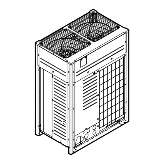
About the units and options Code Explanation Model series Power supply: 3N~, 380-415 V, 50 Hz Power supply: 3N~, 400 V, 60 Hz Minor model change indication 15.3 About the outdoor unit This installation manual concerns the VRV IV, full inverter driven, heat pump system. -
Page 54: Combining Units And Options
About the units and options a VRV IV Heat pump outdoor unit b Refrigerant piping c VRV direct expansion (DX) indoor unit d User interface (dedicated depending on indoor unit type) e User interface (wireless, dedicated depending on indoor unit type) f Cool/Heat changeover remote control switch 15.5 Combining units and options INFORMATION... -
Page 55: Possible Options For The Outdoor Unit
About the units and options RXYTQ10 RXYTQ12 RXYTQ14 RXYTQ16 Possible standard combinations of outdoor units INFORMATION U-series units cannot share the same refrigerant circuit with T-series units. However, electrically, U-series units and T-series units can be connected via F1/F2. ▪ RXYTQ18~48 consist of 2 or 3 RXYTQ8~16 units. - Page 56 About the units and options Description Model name Refnet joint KHRQ22M20T KHRQ22M29T9 KHRQ22M64T KHRQ22M75T For the selection of the optimal branching kit, please refer to "17.1.4 To select refrigerant branch kits" [ 63]. Outdoor multi connection piping kit Number of outdoor units Model name BHFQ22P1007 BHFQ22P1517...
-
Page 57: Unit Installation
Unit installation 16 Unit installation In this chapter 16.1 Opening the unit..................................16.1.1 About opening the units ............................16.1.2 To open the outdoor unit ............................16.1.3 To open the electrical component box of the outdoor unit ................. 16.2 Mounting the outdoor unit ..............................16.2.1 To provide the installation structure ........................ -
Page 58: To Open The Electrical Component Box Of The Outdoor Unit
Unit installation 16.1.3 To open the electrical component box of the outdoor unit NOTICE Do NOT apply excessive force when opening the electronic component box cover. Excessive force can deform the cover, resulting in entering of water to cause equipment failure. 8 HP 2×... - Page 59 Unit installation NOT allowed Allowed (* = preferred installation) ▪ The height of the foundation must at least be 150 mm from the floor. In heavy snowfall areas, this height should be increased, depending on the installation place and condition. ▪ The preferred installation is on a solid longitudinal foundation (steel beam frame or concrete).
-
Page 60: Piping Installation
Piping installation 17 Piping installation In this chapter 17.1 Preparing refrigerant piping ..............................17.1.1 Refrigerant piping requirements ........................... 17.1.2 Refrigerant piping insulation..........................17.1.3 To select the piping size ............................17.1.4 To select refrigerant branch kits..........................17.1.5 About the piping length ............................17.1.6 Piping length: VRV DX only............................. -
Page 61: Refrigerant Piping Insulation
Piping installation ▪ Only use phosphoric acid deoxidised seamless copper. ▪ Foreign materials inside pipes (including oils for fabrication) must be ≤30 mg/10 m. ▪ Temper grade: use piping with temper grade in function of the pipe diameter as listed in table below. Pipe Ø... - Page 62 Piping installation Outdoor unit capacity Piping outer diameter size (mm) type (HP) Gas pipe Liquid pipe 12~16 28.6 12.7 18~22 28.6 15.9 34.9 15.9 26~34 34.9 19.1 36~48 41.3 19.1 D: Piping between refrigerant branch kits Choose from the following table in accordance with the indoor unit total capacity type, connected downstream.
-
Page 63: To Select Refrigerant Branch Kits
Piping installation a Outdoor unit b Main pipes (increase if the equivalent piping length is ≥90 m) c First refrigerant branch kit d Piping between refrigerant branch kit and indoor unit e Indoor unit Size up HP class Piping outer diameter size (mm) Gas pipe Liquid pipe 19.1 →... -
Page 64: About The Piping Length
Piping installation Outdoor unit capacity type (HP) 2 pipes 8+10 KHRQ22M29T9 12~22 KHRQ22M64T 24~48 KHRQ22M75T ▪ For refnet joints other than the first branch (example refnet joint b), select the proper branch kit model based on the total capacity index of all indoor units connected after the refrigerant branch. -
Page 65: Piping Length: Vrv Dx Only
Piping installation Definitions Term Definition Actual piping length Pipe length between outdoor and indoor units. Equivalent piping length Pipe length between outdoor and indoor units. Total piping length Total piping length from the outdoor to all indoor units. Difference in height between outdoor and indoor units. - Page 66 Piping installation Example Description Example 2.1 Multi outdoor Branch with refnet joint Example 2.2 Multi outdoor Branch with refnet joint and refnet header Example 2.3 Multi outdoor Branch with refnet header Example 3 With standard multi layout Indoor unit Refnet joint Refnet header Outdoor multi connection piping kit Maximum allowable length...
- Page 67 Piping installation Total piping length 1000 m/500 m Example 1.1 ▪ a+b+c+d+e+f+g+h+i+j+k+l+m+n+p≤1000 m Example 2.1 ▪ a+b+c+d+e+f+g+h+i+j+k+l+m+n+p≤500 m ▪ Between outdoor branch and outdoor unit (only in case >16 HP) Actual piping length 10 m Example 3 ▪ r, s, t≤10 m; u≤5 m Equivalent length 13 m Maximum allowable height difference ≤50 m (40 m) (if outdoor is located below indoor units) Conditional extension up till 90 m is possible without additional option kit:...
-
Page 68: Multiple Outdoor Units: Possible Layouts
Piping installation 1 Outdoor unit 2 Refnet joints (A~G) 3 Indoor units (1~8) Conditions: The piping length between all indoor units to the nearest branch kit is ≤40 m. Example: h, i, j … p≤40 m It is necessary to increase the pipe size of the gas and liquid piping if the pipe length between the first branch kit and the farthest indoor unit is over 40 m. - Page 69 Piping installation a To indoor unit b Piping between outdoor units NOT allowed (oil remains in piping) Allowed ▪ To avoid the risk of oil retention to the outmost outdoor unit, always connect the stop valve and the piping between outdoor units as shown in the 4 correct possibilities of the figure below.
-
Page 70: Connecting The Refrigerant Piping
Piping installation NOTICE There are restrictions on the refrigerant pipe connection order between outdoor units during installation in case of a multiple outdoor unit system. Install according to following restrictions. The capacities of outdoor units A, B and C must fulfill the following restriction conditions: A≥B≥C. -
Page 71: Multiple Outdoor Units: Knockout Holes
Piping installation WARNING Take sufficient precautions in case of refrigerant leakage. If refrigerant gas leaks, ventilate the area immediately. Possible risks: ▪ Excessive refrigerant concentrations in a closed room can lead to oxygen deficiency. ▪ Toxic gas might be produced if refrigerant gas comes into contact with fire. WARNING ALWAYS recover the refrigerant. -
Page 72: To Connect The Refrigerant Piping To The Outdoor Unit
Piping installation a Left-side connection b Front connection c Right-side connection For side connections, the knockout hole on the bottom plate should be removed: a Large knockout hole b Drill c Points for drilling NOTICE Precautions when making knockout holes: ▪... -
Page 73: To Connect The Multi Connection Piping Kit
Piping installation 17.2.6 To connect the multi connection piping kit NOTICE Improper installation may lead to malfunction of the outdoor unit. ▪ Install the joints horizontally, so that the caution label (a) attached to the joint comes to the top. Do not tilt the joint more than 7.5°... -
Page 74: To Protect Against Contamination
Piping installation 17.2.8 To protect against contamination Protect the piping as described in the following table to prevent dirt, liquid or dust from entering the piping. Unit Installation period Protection method Outdoor unit >1 month Pinch the pipe <1 month Pinch or tape the pipe Indoor unit Regardless of the period Seal the piping and wiring intake holes using sealing material (field supply),... -
Page 75: Using The Stop Valve And Service Port
Piping installation c Taping d Manual valve e Pressure-reducing valve f Nitrogen ▪ Do NOT use anti-oxidants when brazing pipe joints. Residue can clog pipes and break equipment. ▪ Do NOT use flux when brazing copper-to-copper refrigerant piping. Use phosphor copper brazing filler alloy (BCuP), which does NOT require flux. - Page 76 Piping installation 3 When the stop valve cannot be turned any further, stop turning. 4 Install the stop valve cover. Result: The valve is now open. To fully open the Ø19.1~Ø25.4 mm stop valve, turn the hexagonal wrench until a torque between 27 and 33 N•m is achieved. Inadequate torque may cause leakage of refrigerant and breakage of the stop valve cap.
-
Page 77: To Remove The Spun Pipes
Piping installation To handle the service port ▪ Always use a charge hose equipped with a valve depressor pin, since the service port is a Schrader type valve. ▪ After handling the service port, make sure to tighten the service port cover securely. -
Page 78: Checking The Refrigerant Piping
Piping installation 4 When all gas and oil is recovered from the spun piping, disconnect the charge hose and close the service ports. 5 Cut off the lower part of the gas, liquid and equalising stop valve pipes along the black line. Use an appropriate tool (e.g. a pipe cutter). WARNING NEVER remove the spun piping by brazing. -
Page 79: Checking Refrigerant Piping: General Guidelines
Piping installation Method 1: Before power ON If the system has not yet been powered on, no special action is required to perform the leak test and the vacuum drying. Method 2: After power ON If the system has already been powered on, activate setting [2‑21] (refer to "19.2.4 ... -
Page 80: Checking Refrigerant Piping: Setup
Piping installation NOTICE Make sure the pump oil does not flow oppositely into the system while the pump is not working. NOTICE Do NOT purge the air with refrigerants. Use a vacuum pump to evacuate the installation. 17.3.3 Checking refrigerant piping: Setup p <... -
Page 81: To Perform Vacuum Drying
Piping installation To check for leaks: Pressure leak test 1 Test for leaks by applying a bubble test solution to all piping connections. 2 Discharge all nitrogen gas. 3 Break the vacuum by pressurising with nitrogen gas to a minimum gauge pressure of 0.2 ... -
Page 82: To Insulate The Refrigerant Piping
Piping installation 17.3.6 To insulate the refrigerant piping After finishing the leak test and vacuum drying, the piping must be insulated. Take into account the following points: ▪ Make sure to insulate the connection piping and refrigerant branch kits entirely. ▪... -
Page 83: About Charging Refrigerant
Piping installation NOTICE Be sure to turn ON the power 6 hours before operation in order to have power running to the crankcase heater and to protect the compressor. NOTICE If operation is performed within 12 minutes after the indoor and outdoor units are powered on, the compressor will not operate before the communication is established in a correct way between outdoor unit(s) and indoor units. - Page 84 Piping installation NOTICE The refrigerant charge of the system must be less than 100 kg. This means that in case the calculated total refrigerant charge is equal to or more than 95 kg you must divide your multiple outdoor system into smaller independent systems, each containing less than 95 ...
-
Page 85: To Charge Refrigerant: Flow Chart
Piping installation 17.4.4 To charge refrigerant: Flow chart For more information, see "17.4.5 To charge refrigerant" [ 86]. Pre-charging refrigerant Step 1 p < p > Calculate additional refrigerant charge amount: R (kg) Step 2 R410A • Open valves C and B to the liquid line •... -
Page 86: To Charge Refrigerant
Piping installation Charging refrigerant << Continuation of previous page R>Q Step 4 p < p > • Connect valve A to the refrigerant charge port (d) • Open all outdoor unit stop valves R410A Step 5 Proceed with manual charge Step 6 Activate field setting [2-20]=1 Unit will start manual refrigerant charging operation. - Page 87 Piping installation NOTICE During pre-charging, the refrigerant is charged through the liquid line. Close valve A and disconnect the manifold from the gas line. p < p > R410A a Pressure reducing valve b Nitrogen c Weighing scales d Refrigerant R410A tank (siphon system) e Vacuum pump f Liquid line stop valve g Gas line stop valve...
-
Page 88: Step 6: To Manually Charge Refrigerant
Piping installation NOTICE ▪ The refrigerant charging port is connected to the piping inside the unit. The unit's internal piping is already factory charged with refrigerant, so be careful when connecting the charge hose. ▪ After adding the refrigerant, do not forget to close the lid of the refrigerant charging port. -
Page 89: Error Codes When Charging Refrigerant
Piping installation 17.4.7 Error codes when charging refrigerant Code Cause Solution Unusual low pressure on Close valve A immediately. Push suction line BS3 to reset. Check following items before retrying autocharge procedure: ▪ Check if the gas side stop valve is opened correctly. ▪... -
Page 90: Electrical Installation
Electrical installation 18 Electrical installation NOTICE This is a class A product. In a domestic environment this product may cause radio interference in which case the user may be required to take adequate measures. In this chapter 18.1 About connecting the electrical wiring ..........................18.1.1 Precautions when connecting the electrical wiring .................... - Page 91 Electrical installation WARNING ▪ If the power supply has a missing or wrong N-phase, equipment might break down. ▪ Establish proper earthing. Do NOT earth the unit to a utility pipe, surge absorber, or telephone earth. Incomplete earthing may cause electrical shock. ▪...
-
Page 92: Field Wiring: Overview
Electrical installation NOTICE ONLY applicable if the power supply is three‑phase, and the compressor has an ON/ OFF starting method. If there exists the possibility of reversed phase after a momentary black out and the power goes ON and OFF while the product is operating, attach a reversed phase protection circuit locally. -
Page 93: Guidelines When Knocking Out Knockout Holes
Electrical installation Field piping can be routed from front or bottom of the unit (going left or right). Refer to "17.2.4 To route the refrigerant piping" [ 71]. ▪ Be sure to follow the limits below. If the unit-to-unit cables are beyond these limits, it may result in malfunction of transmission: Maximum wiring length: 1000 m. -
Page 94: To Route And Fix The Transmission Wiring
Electrical installation Model Minimum circuit Recommended ampacity fuses RXYTQ16 31.0 A 40 A What? Case 1 Case 2 Phase and frequency 3N~ 50 Hz 3N~ 60 Hz Voltage 380-415 V 400 V Transmission line 0.75~1.25 mm section (a) Maximum length is 1000 m. If the total transmission wiring exceeds these limits, it may result in communication error. - Page 95 Electrical installation 8 HP 10~16 HP a Transmission wiring (possibility 1) b Transmission wiring (possibility 2) . Fix to pipe insulation with tie wraps. c Tie wrap. Fix to factory-mounted low voltage wiring. d Tie wrap. (a) Knockout hole has to be removed. Close the hole to avoid small animals or dirt from entering.
-
Page 96: To Connect The Transmission Wiring
Electrical installation 18.3 To connect the transmission wiring The wiring from the indoor units must be connected to the F1/F2 (In‑Out) terminals on the PCB in the outdoor unit. Tightening torque for the transmission wiring terminal screws: Screw size Tightening torque (N•m) M3.5 (A1P) 0.8~0.96 In case of single outdoor unit installation... -
Page 97: To Finish The Transmission Wiring
Electrical installation 18.4 To finish the transmission wiring After installing the transmission wires inside the unit, wrap them along with the on- site refrigerant pipes using finishing tape, as shown in figure below. a Liquid pipe b Gas pipe c Insulator d Transmission wiring (F1/F2) e Finishing tape 18.5 To route and fix the power supply... -
Page 98: To Connect The Power Supply
Electrical installation 18.6 To connect the power supply NOTICE Never connect the power supply to transmission wiring terminal block. Otherwise the entire system may break down. INFORMATION Installation and routing in case the cool/heat selector is used: refer to the installation manual of the cool/heat selector. -
Page 99: To Check The Insulation Resistance Of The Compressor
Electrical installation e Power supply terminal block f Connect each power wire: RED to L1, WHT to L2, BLK to L3 and BLU to N g Earth wire (GRN/YLW) h Tie wrap i Cup washer j When connecting the earth wire, it is recommended to perform curling. Multiple outdoor units To connect the power supply for multiple outdoor units to each other, ring tongues have to be used. -
Page 100: Configuration
Configuration 19 Configuration In this chapter 19.1 Overview: Configuration................................. 100 19.2 Making field settings................................100 19.2.1 About making field settings ........................... 100 19.2.2 Field setting components............................101 19.2.3 To access the field setting components ........................ 101 19.2.4 To access mode 1 or 2............................102 19.2.5 To use mode 1................................ -
Page 101: Field Setting Components
Configuration Mode 1 and 2 Mode Description Mode 1 Mode 1 can be used to monitor the current situation of the outdoor unit. Some field setting contents can be (monitoring settings) monitored as well. Mode 2 Mode 2 is used to change the field settings of the system. -
Page 102: To Access Mode 1 Or 2
Configuration 2× a Front plate b Main PCB with 3 7‑segment displays and 3 push buttons c Electrical component box service cover Operate the switches and push buttons with an insulated stick (such as a closed ball-point pen) to avoid touching of live parts. Make sure to re-attach the inspection cover into the electronic component box cover and to close the front plate's inspection cover after the job is finished. -
Page 103: To Use Mode 1
Configuration In case of malfunction, the malfunction code is displayed on the indoor unit user interface and the outdoor unit 7‑segment display. Solve the malfunction code accordingly. The communication wiring should be checked at first. Access BS1 is used to switch between the default situation, mode 1 and mode 2. Access Action Default situation... -
Page 104: To Use Mode 2
Configuration 3 Push BS2 10 times. Result: Mode 1 setting 10 is addressed: 4 Push BS3 one time; the value which is returned (depending on the actual field situation), is the amount of indoor units which are connected to the system. Result: Mode ... -
Page 105: Mode 1: Monitoring Settings
Configuration 4 Push BS3 1 time; the value which is returned (depending on the actual field situation), is the status of the setting. In the case of [2‑18], default value is "0", which means the function is not active. Result: Mode 2 setting 18 is addressed and selected, return value is the current setting situation. - Page 106 Configuration [1‑2] Description Unit is currently not operating under power consumption limitations. Unit is currently operating under power consumption limitation. Power consumption limitation can be set in mode 2. There are two methods to activate power consumption limitation of the outdoor unit system. ▪...
-
Page 107: Mode 2: Field Settings
Configuration [1‑40] [1‑41] Shows: ▪ [1‑40]: The current cooling comfort setting. ▪ [1‑41]: The current heating comfort setting. "19.3 Energy saving and optimum operation" [ 111] for more details about this setting. 19.2.8 Mode 2: Field settings [2‑0] Cool/Heat selection setting. Cool/Heat selection setting is used in case the optional Cool/Heat selector (KRC19-26A and BRP2A81) is used. - Page 108 Configuration [2‑9] target (°C) For more information and advice about the impact of these settings, see "19.3 Energy saving and optimum operation" [ 111]. [2‑18] Fan high static pressure setting. In order to increase the static pressure the outdoor unit fan is delivering, this setting should be activated.
- Page 109 Configuration [2‑22] Automatic low noise setting and level during night time. By changing this setting, you activate the automatic low noise operation function of the unit and define the level of operation. Depending on the chosen level, the noise level will be lowered. The start and stop moments for this function are defined under setting [2‑26] and [2‑27].
- Page 110 Configuration If the system needs to be running under power consumption limitation conditions when an external signal is sent to the unit, this setting defines the level power consumption limitation that will be applied for step 1. The level is according to the table.
-
Page 111: To Connect The Pc Configurator To The Outdoor Unit
Configuration [2‑81] Cooling comfort setting Powerful For more information and advice about the impact of these settings, see "19.3 Energy saving and optimum operation" [ 111]. [2‑82] Heating comfort setting. This setting is used in conjunction with setting [2‑9]. [2‑82] Heating comfort setting 1 (default) Mild Quick... -
Page 112: Available Main Operation Methods
Configuration 19.3.1 Available main operation methods Basic The refrigerant temperature is fixed independent from the situation. It corresponds to the standard operation which is known and can be expected from/ under previous VRV systems. To activate this in… Change… Cooling operation [2‑8]=2 Heating operation [2‑9]=6... -
Page 113: Available Comfort Settings
Configuration [2‑8] target (°C) [2‑9] target (°C) 19.3.2 Available comfort settings For each of above modes a comfort level can be selected. The comfort level is related to the timing and the effort (energy consumption) which is put in achieving a certain room temperature by temporarily changing the refrigerant temperature to different values in order to achieve requested conditions more quickly. - Page 114 Configuration To activate this in… Change… Cooling operation [2‑81]=2. This setting is used in conjunction with setting [2‑8]. Heating operation [2‑82]=2. This setting is used in conjunction with setting [2‑9]. Mild Overshoot (during heating operation) or undershoot (during cooling operation) is allowed compared to the requested refrigerant temperature, in order to achieve the required room temperature very fast.
-
Page 115: Example: Automatic Mode During Cooling
Configuration 19.3.3 Example: Automatic mode during cooling 100% 6°C 3°C 35°C A Actual load curve B Virtual load curve (initial capacity automatic mode) C Virtual target value (initial evaporation temperature value automatic mode) D Required evaporation temperature value E Load factor F Outside air temperature Evaporating temperature Quick... -
Page 116: Example: Automatic Mode During Heating
Configuration 19.3.4 Example: Automatic mode during heating 100% 49°C 46°C 2°C A Virtual load curve (default automatic mode peak capacity) B Load curve C Virtual target value (initial condensation temperature value automatic mode) D Design temperature E Load factor F Outside air temperature Condensing temperature Quick Powerful... - Page 117 Configuration E Quick F Powerful RXYTQ Installer and user reference guide VRV IV+ heat pump for high ambient temperatures 4P561157-1B – 2021.11...
-
Page 118: Commissioning
20 Commissioning NOTICE General commissioning checklist. Next to the commissioning instructions in this chapter, a general commissioning checklist is also available on the Daikin Business Portal (authentication required). The general commissioning checklist is complementary to the instructions in this chapter and can be used as a guideline and reporting template during the commissioning and hand-over to the user. -
Page 119: Checklist Before Commissioning
Commissioning CAUTION Do NOT insert fingers, rods or other objects into the air inlet or outlet. Do NOT remove the fan guard. When the fan is rotating at high speed, it will cause injury. INFORMATION During the first running period of the unit, the required power may be higher than stated on the nameplate of the unit. -
Page 120: About The Test Run
Commissioning Pipe size and pipe insulation Be sure that correct pipe sizes are installed and that the insulation work is properly executed. Stop valves Be sure that the stop valves are open on both liquid and gas side. Damaged equipment Check the inside of the unit for damaged components or squeezed pipes. -
Page 121: To Perform A Test Run
Commissioning 20.5 To perform a test run 1 Close all front panels in order to not let it be the cause of misjudgement (except the electrical component box inspection opening service cover). 2 Make sure all field settings you want are set; see "19.2 ... -
Page 122: Correcting After Abnormal Completion Of The Test Run
Commissioning 20.6 Correcting after abnormal completion of the test run The test operation is only completed if there is no malfunction code displayed on the user interface or outdoor unit 7‑segment display. In case of a displayed malfunction code, perform correcting actions as explained in the malfunction code table. -
Page 123: Hand-Over To The User
Hand-over to the user 21 Hand-over to the user Once the test run is finished and the unit operates properly, please make sure the following is clear for the user: ▪ Make sure that the user has the printed documentation and ask him/her to keep it for future reference. -
Page 124: Maintenance And Service
Maintenance and service 22 Maintenance and service NOTICE Maintenance MUST be done by an authorised installer or service agent. We recommend performing maintenance at least once a year. However, applicable legislation might require shorter maintenance intervals. NOTICE Applicable legislation on fluorinated greenhouse gases requires that the refrigerant charge of the unit is indicated both in weight and CO equivalent. -
Page 125: About Service Mode Operation
Maintenance and service 8 HP 10~12 HP 14~16 HP X6A (A3P) X6A (A6P) X5A (A3P) 3 To prevent damaging the PCB, touch a non-coated metal part to eliminate static electricity before pulling out or plugging in connectors. 4 Pull out junction connectors X1A, X2A for the fan motors in the outdoor unit before starting service operation on the inverter equipment. -
Page 126: To Recover Refrigerant
Maintenance and service 22.2.2 To recover refrigerant This should be done with a refrigerant recovery unit. Follow the same procedure as for vacuuming method. DANGER: RISK OF EXPLOSION Pump down – Refrigerant leakage. If you want to pump down the system, and there is a leak in the refrigerant circuit: ▪... -
Page 127: Troubleshooting
Troubleshooting 23 Troubleshooting In this chapter 23.1 Solving problems based on error codes..........................127 23.2 Error codes: Overview ................................127 23.1 Solving problems based on error codes In case of a displayed malfunction code, perform correcting actions as explained in the malfunction code table. - Page 128 Troubleshooting Main code Sub code Cause Solution Master Slave 1 Slave 2 High pressure switch was Check stop valve situation or activated (S1PH, S2PH) - A1P abnormalities in (field) piping (X2A , X3A) or airflow over air cooled coil. ▪ Refrigerant overcharge ▪...
- Page 129 Troubleshooting Main code Sub code Cause Solution Master Slave 1 Slave 2 Discharge temperature sensor Check connection on PCB or malfunction (R21T): open actuator. circuit - A1P (X19A) Discharge temperature sensor Check connection on PCB or malfunction (R21T): short actuator. circuit - A1P (X19A) Discharge temperature sensor Check connection on PCB or...
- Page 130 Troubleshooting Main code Sub code Cause Solution Master Slave 1 Slave 2 High pressure sensor Check connection on PCB or malfunction (S1NPH): open actuator. circuit - A1P (X32A) High pressure sensor Check connection on PCB or malfunction (S1NPH): short actuator. circuit - A1P (X32A) Low pressure sensor Check connection on PCB or...
- Page 131 Troubleshooting Main code Sub code Cause Solution Master Slave 1 Slave 2 Warning indication: Leak Execute autocharge function detection or refrigerant (see manual); unit not ready amount check not performed for leak detection (system operation possible) functionality. Malfunction code: System test Execute system test run.
- Page 132 Troubleshooting Main code Sub code Cause Solution Master Slave 1 Slave 2 Auto address malfunction Check if transmission wired (inconsistency) unit amount matches with powered unit amount (by monitor mode) or wait till initialisation is finished. Stop valve closed or wrong Open stop valves.
-
Page 133: Disposal
Disposal 24 Disposal NOTICE Do NOT try to dismantle the system yourself: dismantling of the system, treatment of the refrigerant, oil and other parts MUST comply with applicable legislation. Units MUST be treated at a specialised treatment facility for reuse, recycling and recovery. RXYTQ Installer and user reference guide VRV IV+ heat pump for high ambient temperatures... -
Page 134: Technical Data
Technical data 25 Technical data ▪ A subset of the latest technical data is available on the regional Daikin website (publicly accessible). ▪ The full set of latest technical data is available on the Daikin Business Portal (authentication required). In this chapter 25.1... - Page 135 Technical data Layout A+B+C+D Possibility 1 Possibility 2 a≥10 mm a≥50 mm — b≥300 mm b≥100 mm c≥10 mm c≥50 mm d≥500 mm d≥500 mm e≥20 mm e≥100 mm f≥600 mm f≥500 mm a≥10 mm a≥50 mm b≥300 mm b≥100 mm c≥10 mm c≥50 mm d≥500 mm d≥500 mm e≥20 mm e≥100 mm a≥10 mm a≥50 mm — b≥500 mm b≥500 mm c≥10 mm c≥50 mm d≥500 mm d≥500 mm e≥20 mm e≥100 mm...
-
Page 136: Piping Diagram: Outdoor Unit
Technical data 25.2 Piping diagram: Outdoor unit Piping diagram: RXYTQ8 (S1NPL) (S1NPH) (S1PH) R21T a Compressor (M1C) l Solenoid valve, oil accumulator (Y2S) b Compressor (M2C) m Solenoid valve, oil1 (Y3S) c Heat exchanger n Solenoid valve, oil2 (Y4S) d Fan o 4‑way valve, main (Y1S) e Fan motor (M1F, M2F) p 4‑way valve, sub (Y5S) -
Page 137: Wiring Diagram: Outdoor Unit
Technical data f Accumulator q Electrical component box g Expansion valve, main (Y1E) r Service port, refrigerant charge h Expansion valve, subcool heat s Stop valve, liquid exchanger (Y2E) i Expansion valve, storage vessel t Stop valve, gas (Y4E) j Subcool heat exchanger u Expansion valve, liquid cooling (Y3E) k Oil separator... - Page 138 Technical data For connection wiring to indoor–outdoor transmission F1‑F2, outdoor‑outdoor transmission F1‑F2, outdoor‑multi transmission Q1‑Q2, refer to the installation manual. How to use BS1~BS3 switch, refer to the "Service Precaution" label on the electrical component box cover. When operating, do NOT short-circuit the protection devices (S1PH). Only for RYYQ model Only for RYYQ/RYMQ model For 8~12 HP: Connector X1A (M1F) is white, connector X2A (M2F) is red.
- Page 139 Technical data E1HC Crankcase heater Drain pan heater (option) F1U, F2U (A1P) Fuse (T 3.15 A / 250 V) Field fuse F101U (A4P) Fuse F401U, F403U Fuse (A2P) F601U, (A3P) Fuse HAP (A*P) Pilot lamp (service monitor is green) K3R (A3P) Magnetic relay K4R (A1P) Magnetic relay (Y1S) K5R (A1P)
- Page 140 Technical data V1D (A3P) Diode V1R (A3P, A4P) Power module Connector X1M (A1P) Terminal block (control) X1M (A5P) Terminal block (power supply)(option) Electronic expansion valve (main) Electronic expansion valve (sub‑cool) Electronic expansion valve (liquid cooling) Electronic expansion valve (storage vessel) Solenoid valve (main) Solenoid valve (accumulator oil return) Solenoid valve (oil 1)
- Page 141 Technical data F601U, (A3P, Fuse A6P) HAP (A*P) Pilot lamp (service monitor is green) K3R (A3P, A6P) Magnetic relay K3R (A1P) Magnetic relay (Y4S) K4R (A1P) Magnetic relay (Y1S) K5R (A1P) Magnetic relay (Y2S) K6R (A1P) Magnetic relay (E3H) K7R (A1P) Magnetic relay (E1HC) K8R (A1P) Magnetic relay (E2HC)
- Page 142 Technical data Connector X1M (A1P) Terminal block (control) X1M (A8P) Terminal block (power supply)(option) Electronic expansion valve (main) Electronic expansion valve (sub‑cool) Electronic expansion valve (liquid cooling) Electronic expansion valve (storage vessel) Solenoid valve (main) Solenoid valve (accumulator oil return) Solenoid valve (oil 1) Solenoid valve (oil 2) Solenoid valve (subcool)
-
Page 143: Glossary
Optional equipment Equipment made or approved by Daikin that can be combined with the product according to the instructions in the accompanying documentation. Field supply Equipment NOT made by Daikin that can be combined with the product according to the instructions in the accompanying documentation. - Page 144 4P561157-1B 2021.11 Verantwortung für Energie und Umwelt...
Need help?
Do you have a question about the VRV IV+ RXYTQ8U5YF and is the answer not in the manual?
Questions and answers
Where are heat pump
The Daikin VRV IV+ RXYTQ8U5YF heat pumps are intended for outdoor installation and are designed for heat pump air-to-air applications. They are available in single and multi-module configurations with heating capacities ranging from 25 to 50 kW and cooling capacities from 22.4 to 45 kW.
This answer is automatically generated